The Hiorth Brothers Build

Dear builders

We would like to contribute to this awesome new sport and DIY projects! We are three brothers from Norway, one eye-doctor and two mechanical engineers, we also get help from some of our very talented friends that are into electronics and programming.

We decided to make a thread where we will show different aspects of our build and how we solved challenges we came across (Cooling ESC, Gearbox, Waterproofing, Mast mount, Duct, Controller, propellers etc). Hopefully both you and we will learn from this. We will also answer questions related to our approach as best we can to guide other builders to their own flying watercraft. If you have a question, please add a picture to describe your question (you can take pictures from our facebook album, this way we can answer more precise).

We have been documenting our journey on a Facebook album.

We have also published an instructable, with all you need for our V1 propulsion unit. Our v1 is still working well, we still ride it!

Our Bluetooth remote is now up and working, and we will soon be publishing to this thread, with code and stl´s for 3d printing. Note that these files and/or information are not intended for commercial use and should not be sold to a third party as “your/our” information!!!

We get many inquiries about getting/buying our latest files, we have decided not to share these. They are milled hence not ideal for DIY building. We also belive that people will be much more excited with the building if they implement their own design changes, which in our heads is the best part of this new sport/ DIY project!

We are also looking into building a commercial board and/or a DIY kit for people without workshops (if there is sufficient demand for this. let us know).

To kick off the discussion Here is a few pictures and video of how we did some of our challenges.


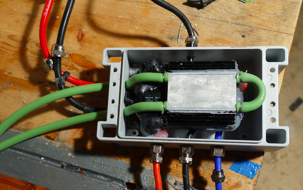
The esc is placed inside a fireproof aluminium box from RS-components, that also act as a passive heatsink(together with be compartment lid, which is also aluminium). Silicone tubes are used to pump water through the ESC.


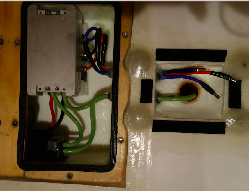
ESC box inside the board. With the cooling pump (self priming). The water is pulled through the mast and into the pump and through the esc and out.


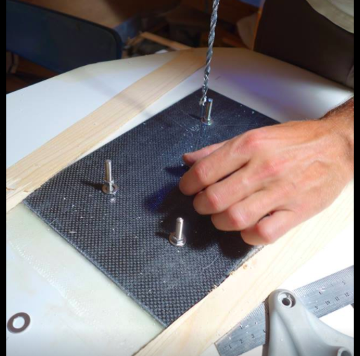
Mast mount, is done with threaded rods that are glued in and reinforcements on each side of the board. Does not look too good, but its cheap and super sturdy.


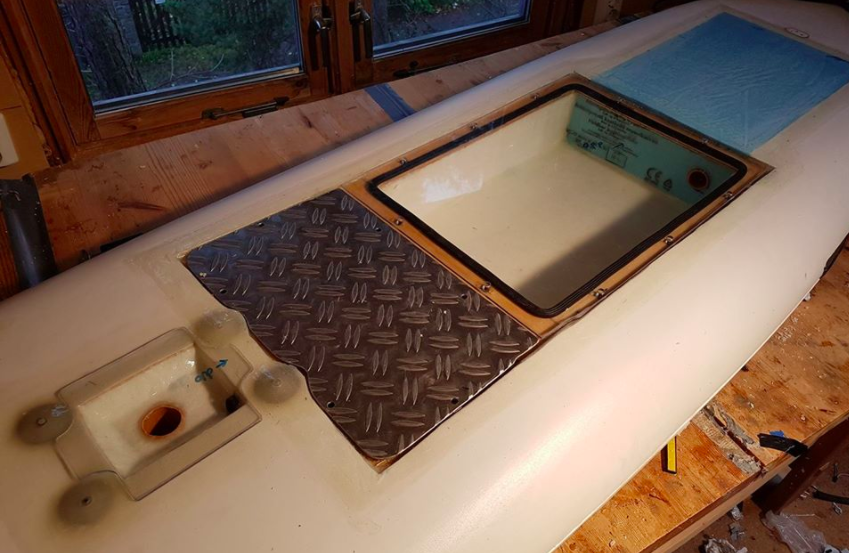
The board compartment is build in a old windsurf Board. 3 layers of fiberglass was vacuume bagged onto the board to strengthen the compartment. Several snowboard inserts is used to make the lid, combined with a EPDM foam seal makes a waterproof compartment.


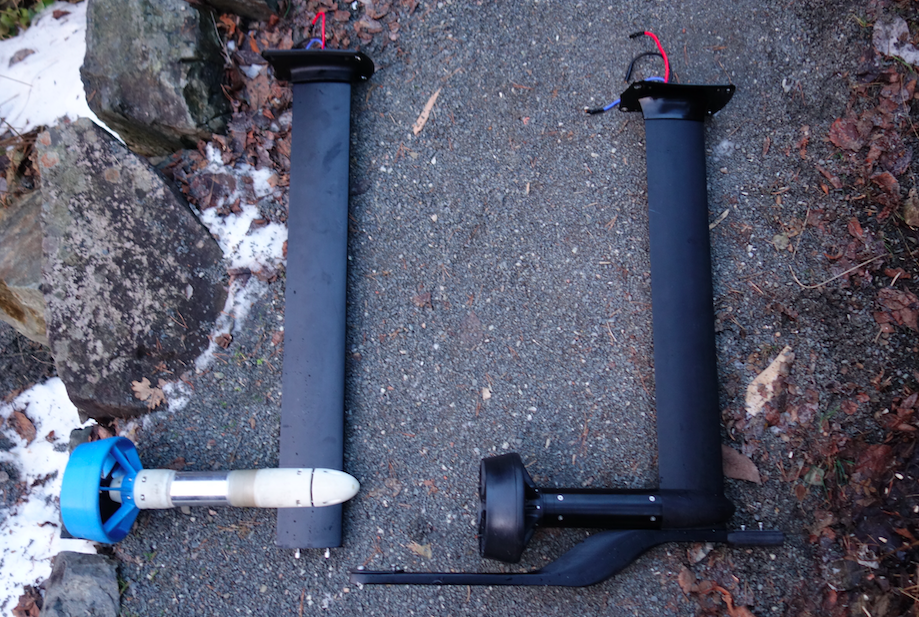
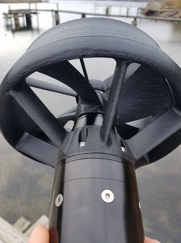
Comparison of Propulsion unit v1 and v2.


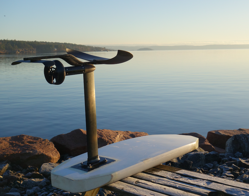
Board with perfect background


Sunset foiling :slight_smile:

Videos:

CHEERS :slight_smile: :slight_smile:

29 Likes

VERY NICE !
PERFECT BUILD , for some slow rides,…

Next ?? High Speed ??

Greets Belgium

Yep, high speed is one of our next goals. We used this foil to learn to ride (we have never been foiling before), its stable and easy to learn on and reaches about 30km/h max.

Our propulsion unit 3.0 as in attached picture (naca 0012 duct) combined with a smaller windsurf foil and different propeller will hopefully improve speed to 40km/h (maybe more).

4 Likes

Looks allready very nice,…

Work On :slight_smile: (says the boss)

1 Like

We decided to go with gearbox. It does make the propulsion system slightly more complicated but there are also several benefits. It seems like a perfect motor: small diameter (>60mm), Low KV, Inrunner, high efficiency is hard to build and get to work properly. A perfect motor would be great!!! At the same time we would not like to trade of efficiency for a less complicated system.

Here is a list of our view on pros/cons. Keep in mind that we would still like the perfect motor and no Gearbox, but it might be hard to achieve.

Con Gearbox

  • Complexity of propulsion unit
  • Cost (altho this is justified by less cost in ESC and battery because of higher efficiency)
  • Gearbox can break under load
  • Added Length of propulsion unit

Pro Gearbox

  • Efficiency 1. Because we can use a larger prop, Secondly because the system will be lighter (less need from batteries, ESC and smaller wires)
  • Less stain on electric system (battery and ESC) due to lower amp draw.
  • Lower overall cost (and weight) for the same amount of run time/thrust.


Our powertrain, TP power 440KV motor, and 5:1 gearbox

2 Likes

The best thing is to have prop and jet in the same setup, I have tried both, at this time the one that gives me more tranquility is jet, I only have a little less flight time but that is not a problem for me, I can change easy more battery packs, the feeling is different, there is no need for maintenance, I do not need protection , also has a lot of power and speed when flying, I am very happy with this system, is an eternal system!

4 Likes

The RC Forum is wrong and also the corrections made there are wrong. They citated or interpreted wrongly german wikipedia.
If you have a look at the english wikipedia “thrust” you come to such formula {\displaystyle \mathbf {P} ^{2}={\frac {\mathbf {T} ^{3}}{4\rho A}}} :
Thrust = (Power^2 * 4 * density * Area)^(1/3)
so if you keep Power and density at constant you get:
Thrust is proportional to Area^(1/3)
which is not a steep function at all. At a doubled Area you just get 25% more thrust. With a doubled diameter you get 58% more thrust.
This equation is valid for jets at standstill. Maybe you can compare bollard pull by this equation.
But these equations are not considering any side effects you get by the added drag of larger area or diameter of the shroud and prop tips.
I would not rely on these theoretic physical equations when making the design decision gear vs. direct drive. With a 440Kv and 5:1 gear you almost get the same values as with 100Kv and no gear. I agree that the magnet system limits the torque, so it is independent of the Kv but proportional to the volume of the air gap diameter^2 x length. For a direct drive 6384 this volume is 53x50mm = 110 ccm or even 53x55mm = 121ccm if optimized. I expect to get around 7Nm maximum. Whats the active magnetic volume of inrunner TP5670? What is the diameter and length of your rotor?

3 Likes

Thanks for the input, I removed the wrongly interpreted information, should never blindly trust forum posts :stuck_out_tongue: . But there may still be a gain in efficiency.

As you say, the equation is for standstill environment, what will happen with the efficiency when the propeller is traveling through water?

Have you built your system, does it run well with the direct drive?

We are looking at a heavy duty 100KV out-runner to try direct drive, but the diameter is close to 90mm with the waterproofing it will be maybe 95mm which would result in drag.

I dont know the magnetic volume, but its the TP5840 with attached motor spec.

Can you explain like I am 5?

3 Likes

Found this propulsion theory on larger ships.

In general, the larger the propeller diameter, the higher the propeller efficiency and the lower the optimum propeller speed referring to an optimum ratio of the propeller pitch and propeller diameter.

Number of propeller blades Propellers can be manufactured with 2, 3, 4, 5 or 6 blades. The fewer the number of blades, the higher the propeller efficiency will be. However, for reasons of strength, propellers which are to be subjected to heavy loads cannot be manufactured with only two or three blades.

We will go with 3 blades, or maybe 2 on next edition.

Its a compromise. Try capped commercial props. Put them in a shroud or duct. My next design i am planning with 14cm diameter of prop. Coming from 17.5cm, almost no capping in a low drag shroud.
This was too heavy for the ESC. Try 11-15cm.
I love your project!

Got this basic propeller formula from a friend that does his phd on hydrofoils/hydrodynamics, its very simplified, but it takes into account that the propeller is moving through a medium.

02
10

There are several important trends that are apparent upon consideration of these equations. We see that the propulsive efficiency is zero when the flight velocity is zero (no useful work, just a force), and tends towards one when the flight velocity increases. In practice, the propulsive efficiency typically peaks at a level of around 0.8 for a propeller before various aerodynamic effects act to decay its performance as will be shown in the following section.

Assumptions:
Flight velocity: 20km/h = 5.6m/s
Thrust: 300N (might be a bit high)
Propeller diameter: 140mm, 70mm and 50mm ( We only play with this size in this example)

Propulsive efficiency with prop-diameter 140mm= 0.80 (140mm looks like a good size for our use)
Propulsive efficiency with prop-diameter 70mm= 0.58
Propulsive efficiency with prop-diameter 50mm= 0.47

So a prop diameter of 140mm compared to a prop diameter of 70mm theoretically gives 38% higher efficiency, which is a LOT. The practical efficiency gain is probably lower due to a larger duct drag, but still…

Another interesting formula, which gives us the Power needed for a certain speed/thrust (given an ideal propeller), from the same variables. This values are a bit easier to comprehend.

25
This is the ideal (minimum) power required to drive the propeller. In general, the actual power required would be about 15% greater than this.

Assumptions power consumption with “ideal propeller”:
Flight velocity: 20km/h = 5.6m/s
Thrust: 300N (might be a bit high)
Propeller diameter: 140mm, 70mm and 50mm ( We only play with this size in this example)

Power needed to run at 20km/h with an optimal prop, diameter 140mm= 2098W
Power needed to run at 20km/h with an optimal prop, diameter 70mm= 2892W
Power needed to run at 20km/h with an optimal prop, diameter 50mm= 3593W

These values are similar to the values we have measured on our system (We do not have a optimal propeller) but we can see that the correlations are there!

4 Likes

Nice formulas, maybe i should get some book!


Too nice to be true, the bigger the diameter, the better eta becomes. With infinite diameter or area the eta is 100% and power is T*u0.
So there must be missing something.
There must be some increasing drag from the shroud and the prop itself, as the diameter is growing.
The 15% is a very general assumption, i assume.
At least one thing is clear: 50mm is too small, 175mm is too large.

One more question: What is the active magnetic volume of your motors? What is the diameter and length of your magnetic rotor inside the inrunner?

@virus: Whats your prop diameters in the two configurations?

56mm jet carbon fiber
120mm prop aluminium

Nice graph! @PowerGlider

In practice, the propulsive efficiency typically peaks at a level of around 0.8 for a propeller before various aerodynamic effects act to decay its performance

So I suppose the factors should be around 0.8 to take into account the negative effects of a infinite large propeller that of course would be bad. The phd foil guy also told me that a factor of around 0.9 would be ideal, as hydrofoils is a special case where there are more “room” for the propeller. Furthermore after some more calculations and advice from our friend we belive 150-200N thrust is a more accurate estimate. In that case a correctly designed Ø160mm propeller should be pretty good for our setup.

The formulas are really simplified, so I guess they are only valid in “usual” cases, not with infinite large propellers :slight_smile: .

@PowerGlider I dont know the magnetic volume, the motor is inside the Propulsion unit now, would be too much of work to get it out just to measure :stuck_out_tongue: The aluminium casing is 92mm long and Ø58mm if that helps.

Did a small run the other day. This is with 2x6s16000mah batteries. At the end there was 3.70-3.75 Volts left on all cells. The setup is with a 4 blade 140mm prop, rice speed nozzle shroud with 5 degrees AoA and twisted stators downstream of the propeller.

Should definitivly be possible to increase the run time by improving propeller design!

7 Likes

I am planning a shrouded prop, so if the diameter gets too large there are additional grids necessary to protect your foot or fist from touching the prop from the inlet side. The outlet is not protected as rotating blades will not harm anything, because they will repell everything with their angle of attack. This is kind of bloody experience i made with aero props.
My 17.5cm design had two horizontal fins as a grid (in combination with the vertical fin), for 14cm i plan to have a single horizontal fin, please have a look here: Direct drive outrunner with direct water cooling - #79 by PowerGlider - Propulsion System (Motor, Gears) - FOIL.zone
By this i hope i can reduce drag a lot and overcompensate the lesser efficiency of reduced area.

@Hiorth That’s a great looking enclosure. Is the sealing rubber a clip on style or is it glued to the edge of the plywood.

Its a double sided tape, which is taped onto the epoxy and fiberglass coated plywood, works like a charm.

1 Like

@Hiorth Great job. Did you use a router or a special tool to hollow out the board or did you do it by hand? Also how close did you need to cut towards the bottom of the board? My board is only 100mm thick and I’m concerned that I will weaken the board if I go to deep