Hi Max congrats on your board, nice work. So much sanding, puts me off a bit from starting…
What is the weight of your board (just board, without foil, batteries etc.)?
Thank you. Yes, they should be in the instructable. Inside the embedded Fusion 360 viewer. Can you download them?
It weighs 3.8kg at 150x50x14cm. The sanding was ok. A silicone dust mask is a must though and a vacuum that is hooked up to the sander. The worst part for me was that the board looks like a pice of junk up to the point you paint it.
No, I don’t think I can do that via the viewer.
Maybe you know a trick ?
Will sort out the files this week.
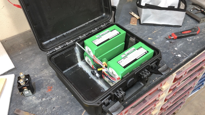
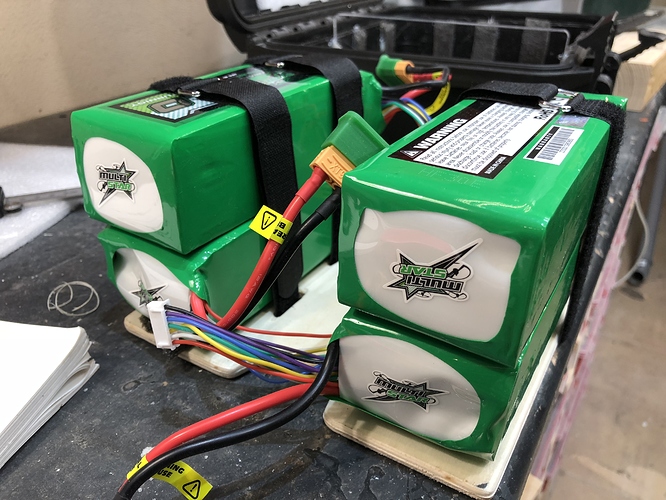
I started adding the electrics. The batteries will be at the very front of the board. This uses the space most efficiently. I want to be able to access all the components without having to remove anything.
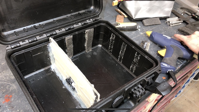
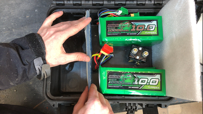
I added an acrylic wall to separate the batteries from the receiver, UBEC, Arduino and mini Relais. Acrylic so I have enough light. Polycarbonate would be nice, but I don’t have any. This is not to keep things waterproof, but rather to protect the batteries and to keep everything in place. I don’t want things to rattle around.
Everything is glued on with hot glue. It does not stick very well to the polypropylene. So i used a chissel and roughed it up really good. I cut little pieces that hopefully interlock with the hot glue. So far it looks like it works. I did not want to use rivets to keep everything waterproof. Tips are welcome.
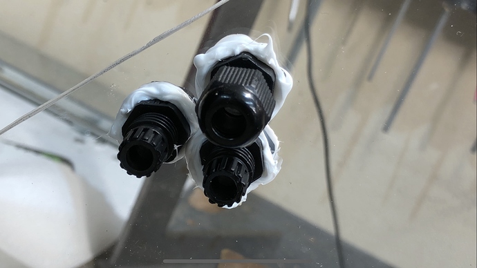
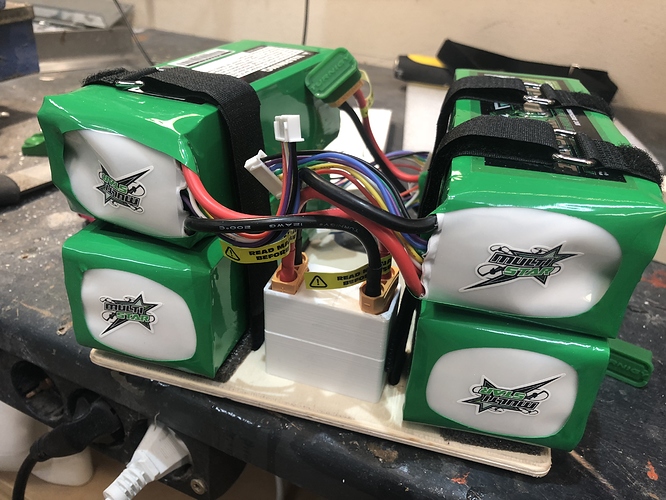
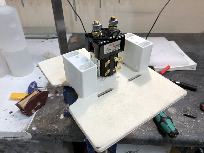
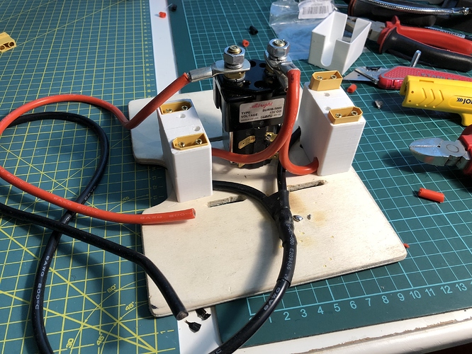
I printed these terminal blocks to hold XT90 connectors. That way the cables will be neatly held in place and they can be easily plugged in.
2 batteries in series and 2 of them in parallel. Anything beyond that will be in XT150 connectors.
Great idea. Would you be able to share STL file please
The battery cables are soldered up. The batteries plug into the white blocks. Front and back each form a 12s battery.
I am not sure how warm those cables will get. Each plastic block could have 100A going through. Will the XT90s soften the PLA?
did you soldered the wires for the relay ? (can’t tell on the pics) , nice built ![]()
i have that : Caméra thermique personnelle FLIR ONE pour iOS - Apple (FR)
to check temp, work great for many application
Nice, but a bit pricey. They are only crimped on with a vice. Much easier than soldering.
If you are really unsure about any critical connection, you could just glue a temporary ntc thermistor on it. Those are pretty easy to monitor with an arduino. A cheap thermocouple would probably also be fine. Just pass your max current through the connection and watch the temp develop.
Thanks. I already bought 5 thermistors and 4 cheap thermometers.
I made a lot of progress today. Most of the thick wires are soldered.
—————————————————-
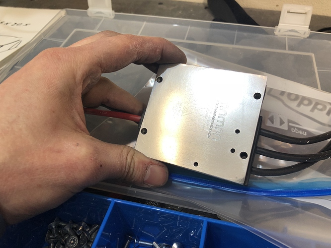
I polished the VESC with ever finer getting sandpaper. The original looked flat but was actually very cupped. Now it should make a good surface to transfer the heat to the ESC housing.
————————————————-
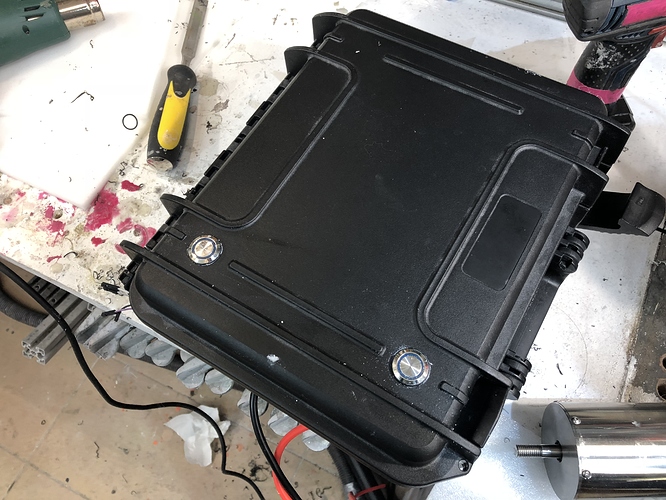
Two buttons were added. One for the UBEC and the second one as a start button.
——————————————————
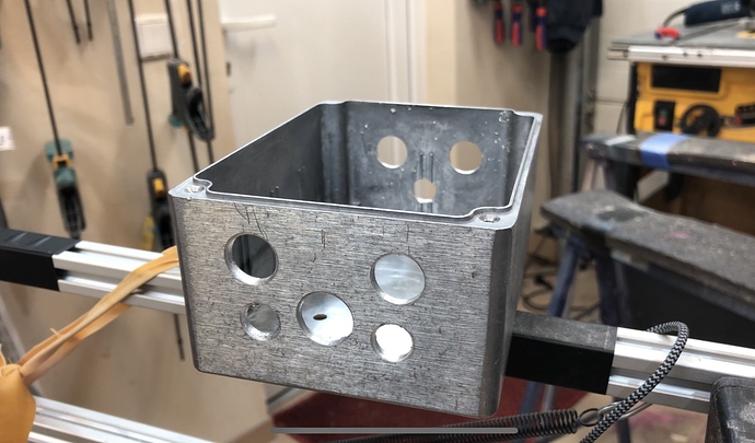
The ESC box is full of holes now. Different sizes for different cable connectors. MY XT150 cables will fit through, but without the plastic housing. Bullet connectors only.
——————————————————-
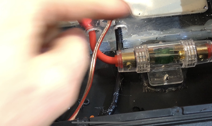
I installed the main fuse.
———————————————————
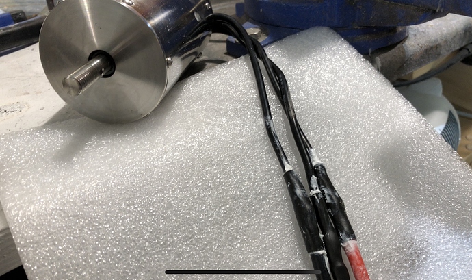
The motor wires were soldered on. This is AWG 8 to AWG 12. The VESC and motor both have AWG 12. Nothing I can do about it I guess. But all other cables are future proof if I get a more powerful ESC.
I waterproofed the connection by coating the solder joint with silicone and then adding heat shrink tubing while it was still fresh. I will add a second layer when longer heat shrink arrives.
You’re almost ready for water!! Even if the player will go soft with the heat… The XT90 will still connected, I guess you can run a real test and figure out later if those fancy cable organizer kept up with the power
Almost ready for water testing. Only issue was the snow this weekend.
Here is a video update:
Those flat buttons on the case, with the light around, are those watertight? I don’t remember where but I read that they don’t have a suitable IP grade…or maybe certain models don’t.
I have the same ones
from memory they are IP67
Ebay seller says they are. Not sure if thats true.
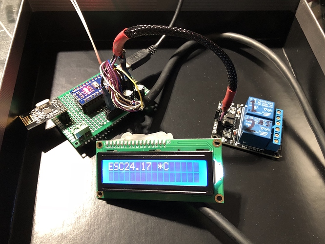
I got 90% of the electronics inside the board done. Every component is inserted into sockets instead of soldered on. That way I can change out components in case I fry them. I learned this lesson on my previous previous Arduino project.
What you see there is the wireless module, two relays, an LCD, temperature sensors and the green screw terminal for the main power switch.
I have one UBEC which has to power the Arduino and the big relay at 12V. But I also have a 5V USB LED strip. Do I need to get a second UBEC for that? Or have you got a better idea?
