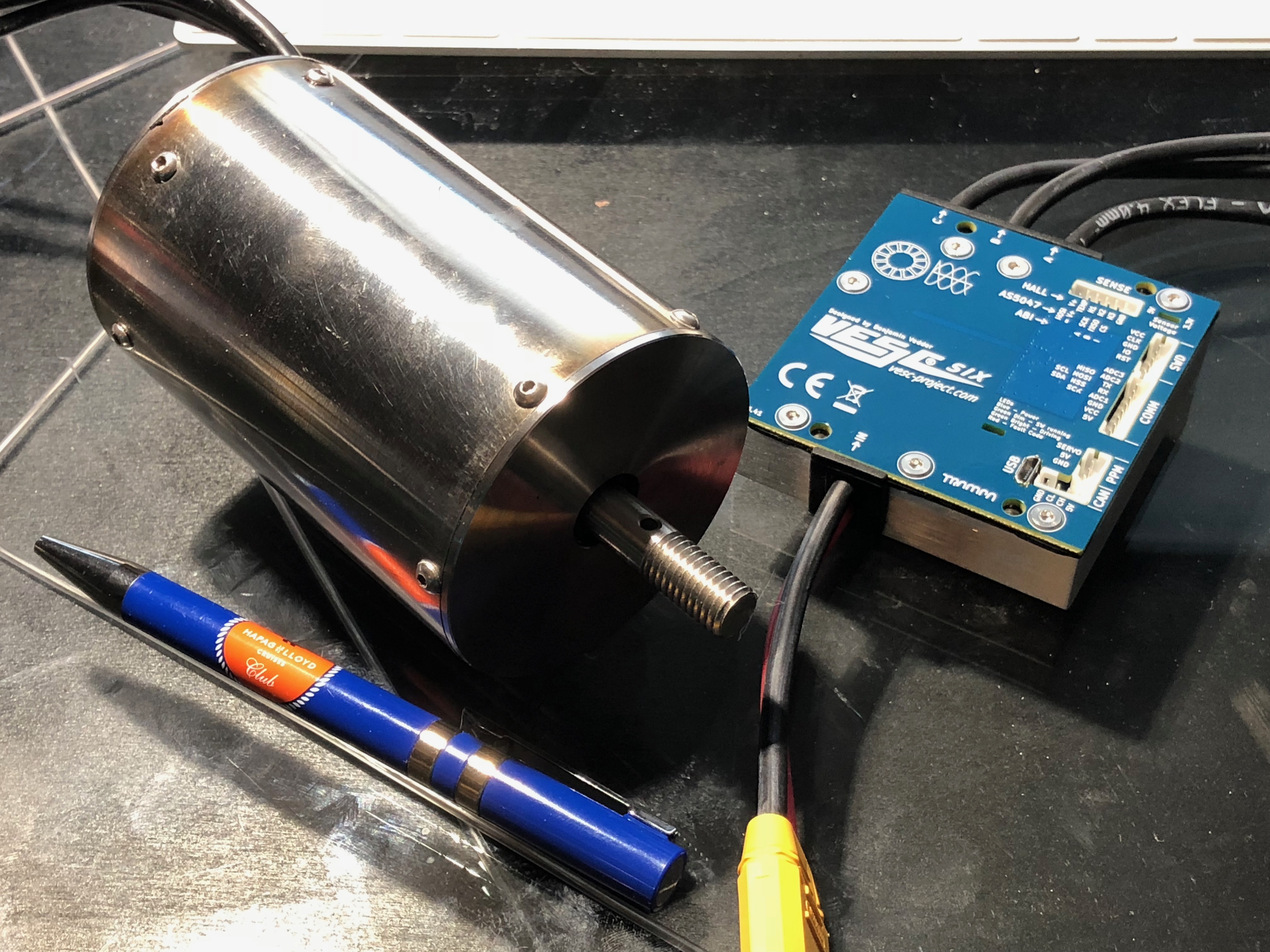
So the VESC 6.4 arrived today together with the waterproof motor from Alien. I am not sure if the motor will be powerfull enough, but we will see I guess. Same goes for the ESC. I chose it because it is small and has a lot of safety and data logging features. It is also very suitable to mount it to a large metal heat sink. Something no other ESC had.
It looks like the motor is sealed with silicone everywhere. I don´t want to take it apart. Bruno said that it is an outrunner and that there are cooling chanels somewhere. No idea how it looks like on the inside. I also don´t know if there is a thrust bearing. Bruno said it is made for taking the load of a prop. He doesn´t really answer the questions that you send him.
The cables on both are just 12AWG. I have 8AWG for everything else (which is bigger). Do you think the cables on the motor and the VESC matter much? They are short and submerged in water anyway.
Is there a temperature sensor inside the motor? The Vesc has a motor temp input to protect it from overheating. I think it has no water cooling inside.
I would take these steps:
Take measurements with the vesc to document the resistance, no load current and Kv. Swap motor phases several times to be confident.
Mount a temp sensor to the winding, get some hints how to take it apart maybe from other users or the manufacturer. Ask also what the temp limit of the magnets is. Program the vesc to limit motor current between around the magnets temp.
Mount a prop, test it unsubmerged and uncooled, get some real time data from temp sensor at different phase current settings.
Unmount the prop, heat up the motor to e.g. 60°C in an oven statically, so all components inside have the same temp. Submerge it and let it run with no load current for some minutes with temp data readings.
What can you do with this data?
From the phase resistance and the current you calculate the ohmic losses and add the no load current to get the powerloss which is produced inside the motor. Together with the temp sensor reading you get a heat up curve and can estimate the thermal capacity. From the 4. measurement you can estimate the thermal resistance from winding to outer surface.
Try to set up a simplified thermal model with capacitors, resistors, voltages(equals temp), current sources (equals powerloss) using Matlab or simply Excel by feeding it with real time data and the simplified thermal model and a fit algorithm to find the parameters.
With this thermal model try to simulate some scenarios with startup processes and foiling phases and pauses.
If its overloaded by permanent foiling, forget it,
if it is overloaded by frequent startups, use the temp sensor,
If it is never overloaded go flying.
About the cables. I think the vesc6 has AWG11 wires which is on the boarder. Maybe you can resolder with bigger ones, but that costs your warranty or keep them short with a massive plug or solder interface. The motor wires you cannot change, its too risky.
Good luck!
No sensors inside. I would love to add one but I have no idea how to open this thing. It sounds stupid, but everything is covered with sealant. If I apply force to anything, I don’t know weather I am pulling on the sealant, magnets or bearing assemblies. Ill try.
Did we not have photos somewhere where it is in pieces?
Max, the video is awesome!! thanks for that.
I’m sure just filming and editing is a huge chunk of work, not to mention the epic work you put into the actual board, wow!
Hi Max !
I watched your video: Amazing job here with the board and videomaking ! Such a professionnal work, very inspiring !
Thanks for sharing !
Are you also sharing the CAD file of the board ?
Hi Max congrats on your board, nice work. So much sanding, puts me off a bit from starting…
What is the weight of your board (just board, without foil, batteries etc.)?
It weighs 3.8kg at 150x50x14cm. The sanding was ok. A silicone dust mask is a must though and a vacuum that is hooked up to the sander. The worst part for me was that the board looks like a pice of junk up to the point you paint it.
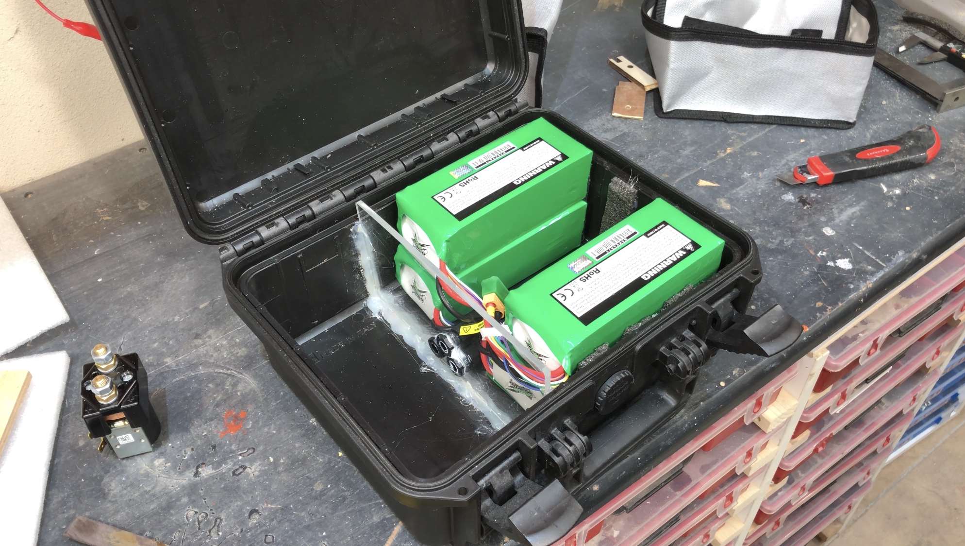
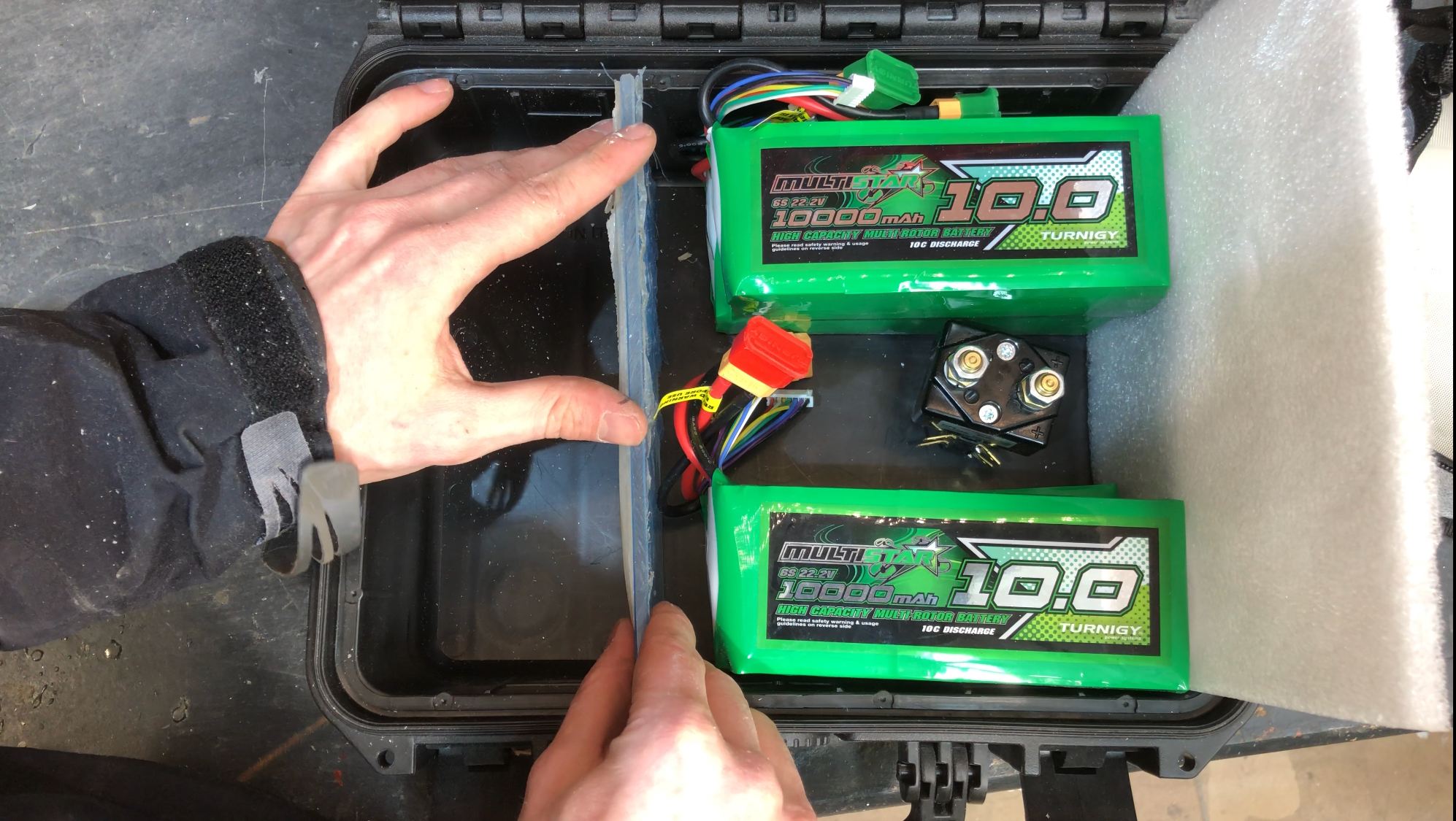
I started adding the electrics. The batteries will be at the very front of the board. This uses the space most efficiently. I want to be able to access all the components without having to remove anything.
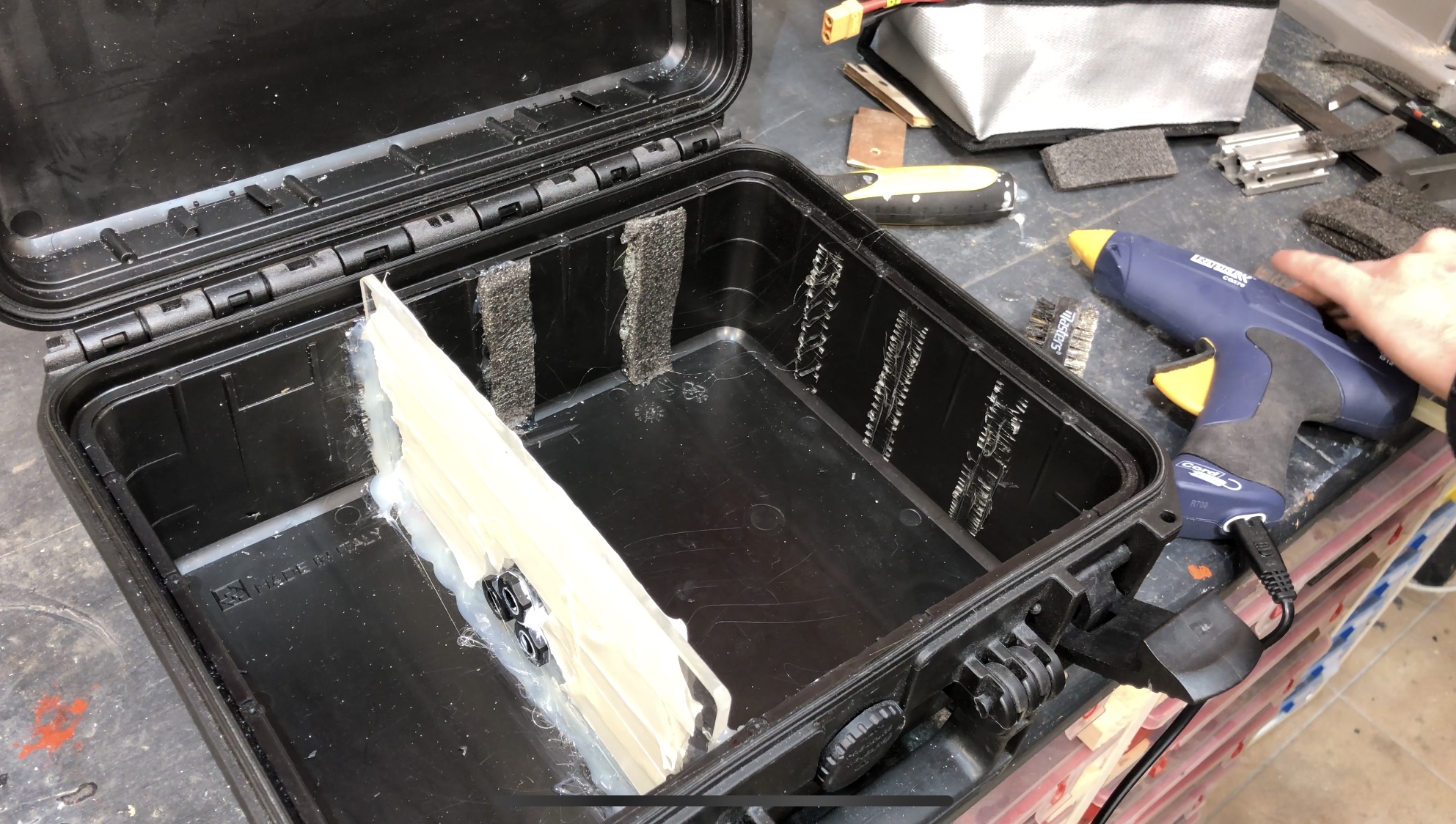
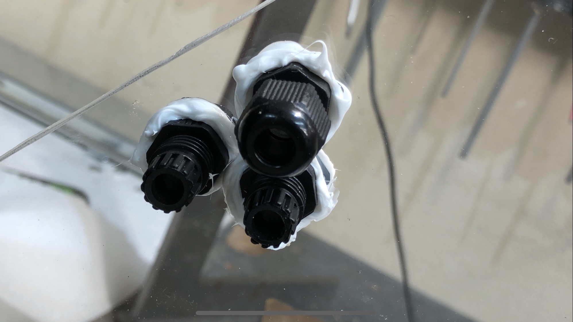
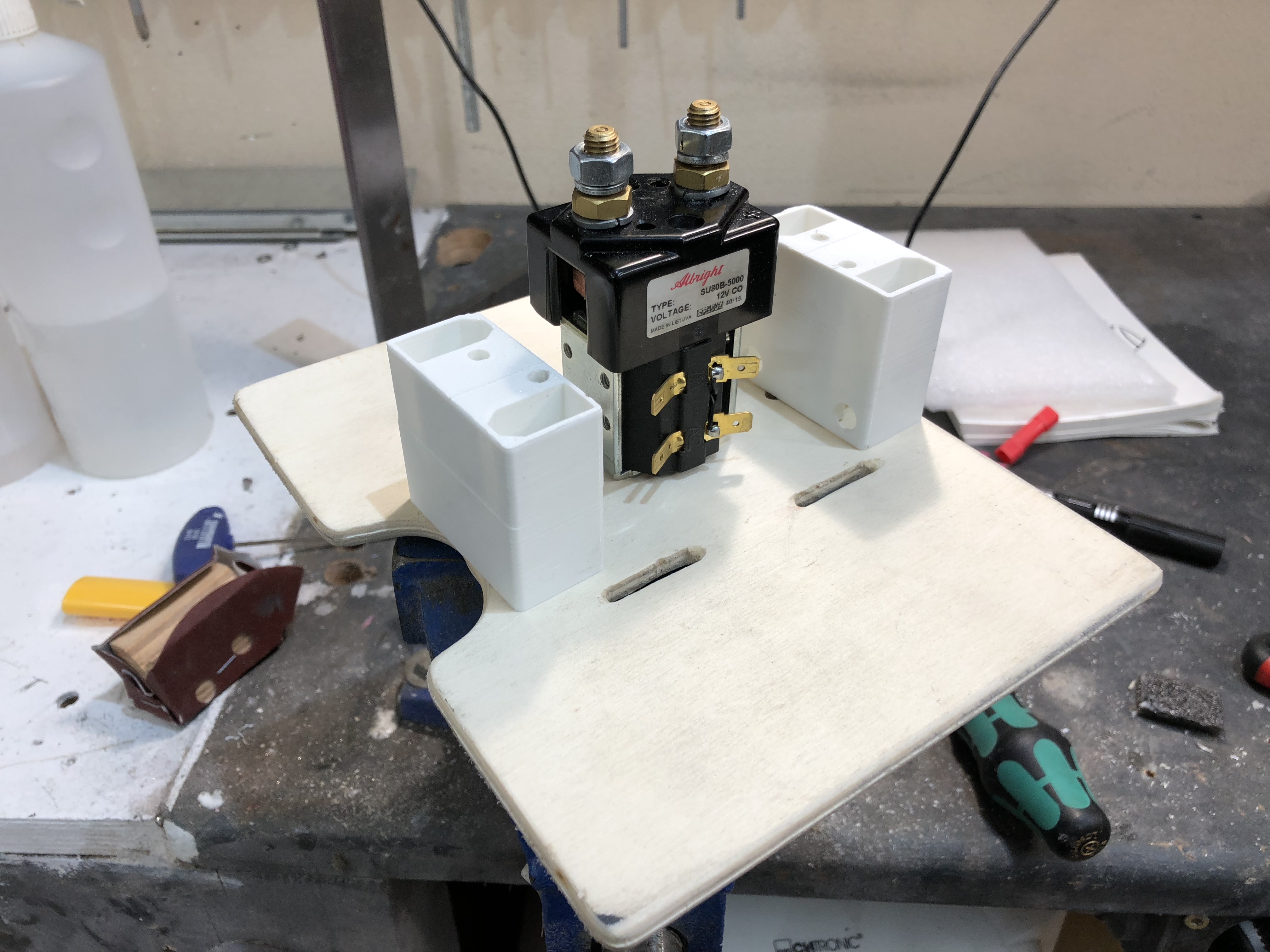
I added an acrylic wall to separate the batteries from the receiver, UBEC, Arduino and mini Relais. Acrylic so I have enough light. Polycarbonate would be nice, but I don’t have any. This is not to keep things waterproof, but rather to protect the batteries and to keep everything in place. I don’t want things to rattle around.
Everything is glued on with hot glue. It does not stick very well to the polypropylene. So i used a chissel and roughed it up really good. I cut little pieces that hopefully interlock with the hot glue. So far it looks like it works. I did not want to use rivets to keep everything waterproof. Tips are welcome.
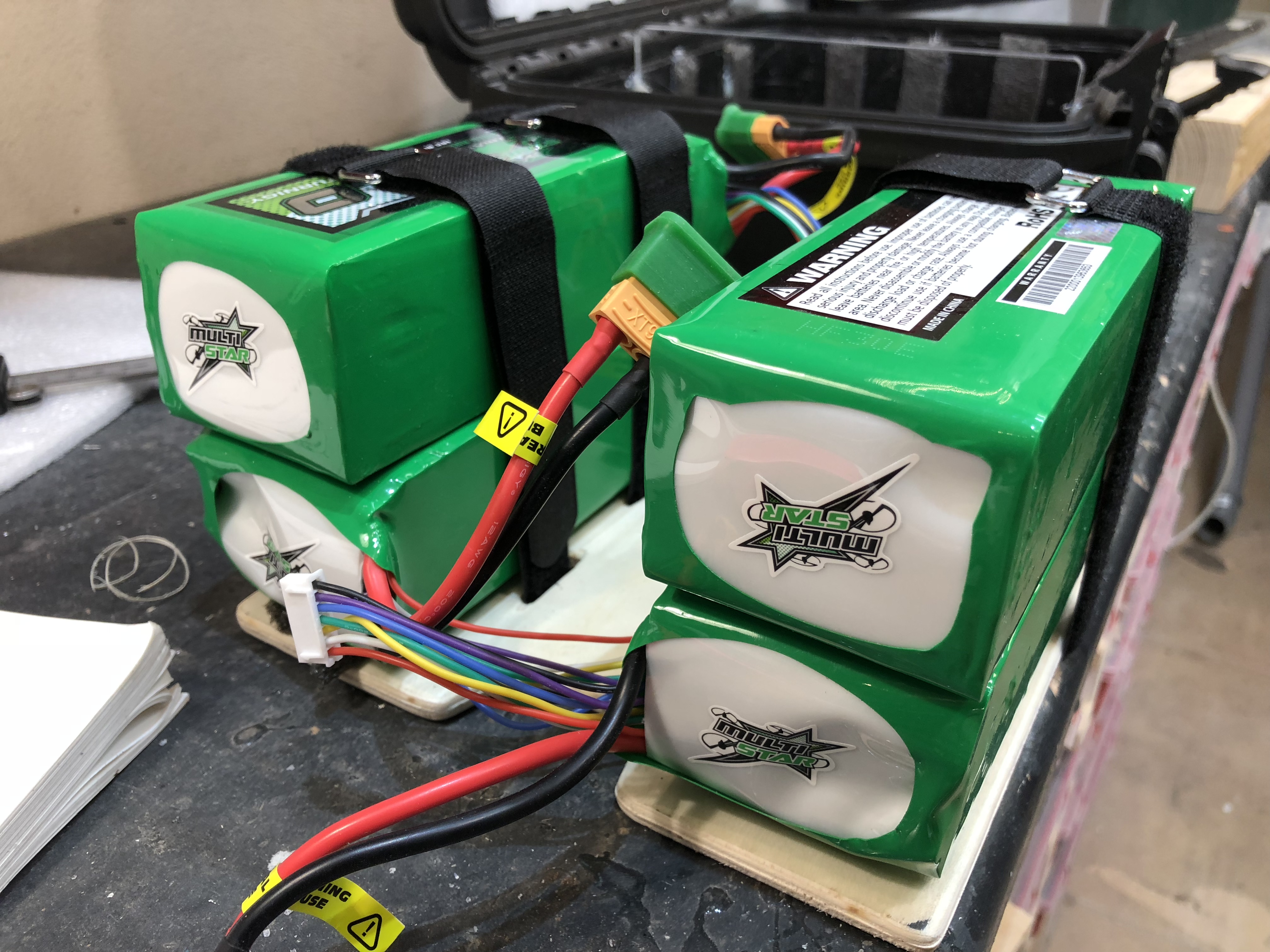
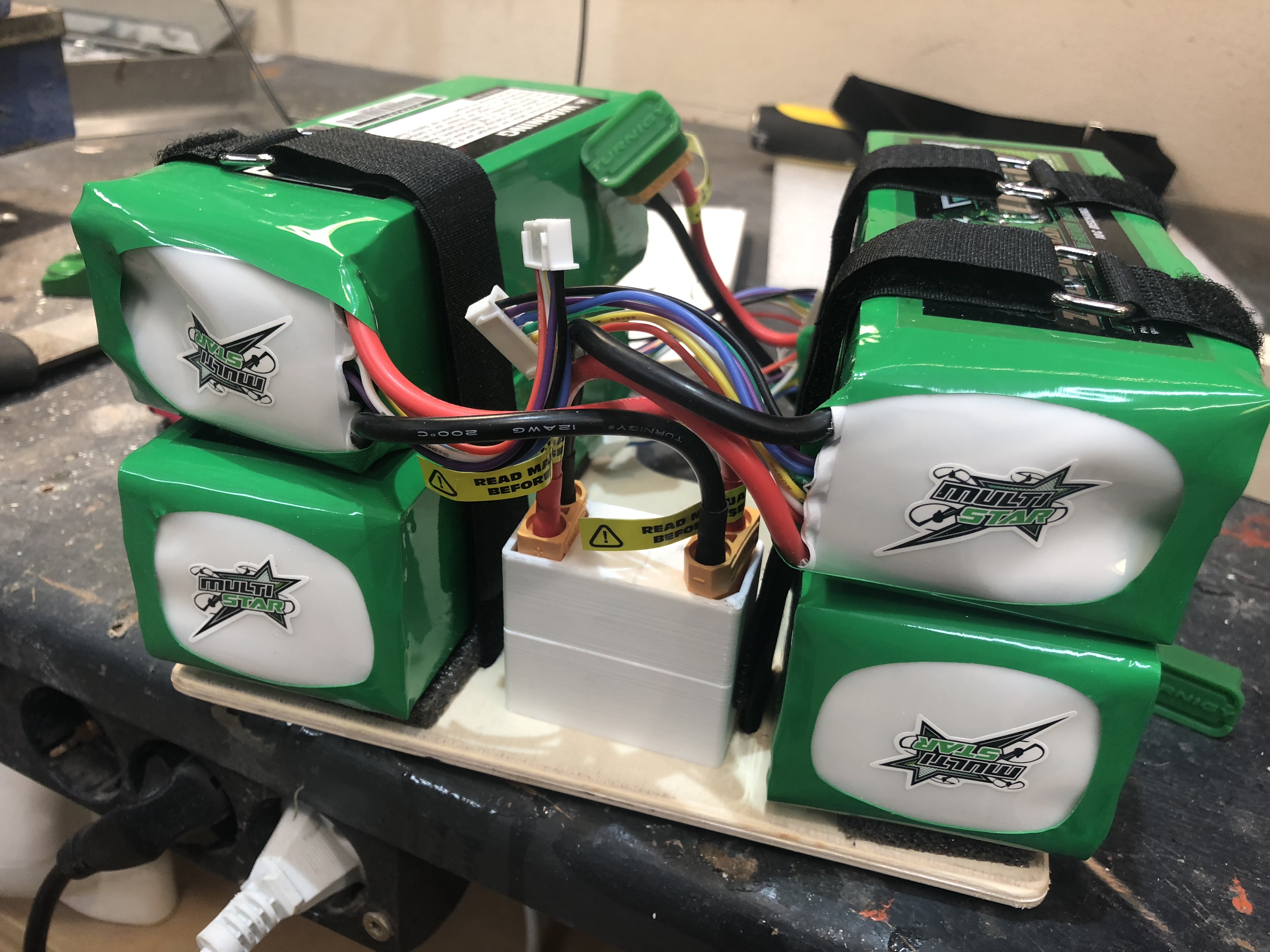
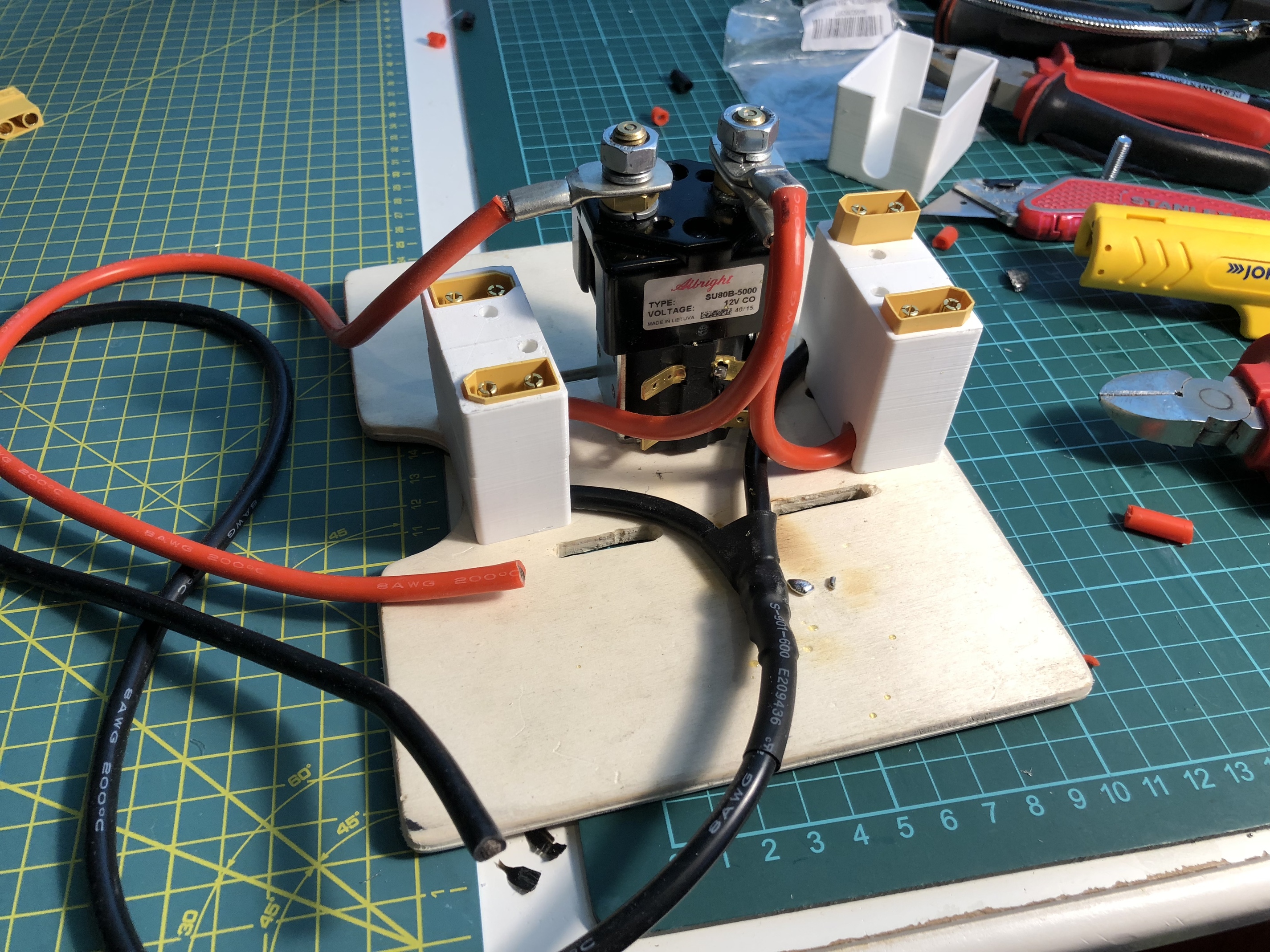
I printed these terminal blocks to hold XT90 connectors. That way the cables will be neatly held in place and they can be easily plugged in.
2 batteries in series and 2 of them in parallel. Anything beyond that will be in XT150 connectors.
If you are really unsure about any critical connection, you could just glue a temporary ntc thermistor on it. Those are pretty easy to monitor with an arduino. A cheap thermocouple would probably also be fine. Just pass your max current through the connection and watch the temp develop.