The transom mod heleped a bit. With the 3 blade propeller still problem with ventilation but got it on the plane, about 17 kmh. Then changed to the odd 2 blade plastic. felt much better, and did almost 20 kmh.
To get clearer water for the prop added a piece of wood behind the transom. This way got the propeller about 25 mm further stern. Still not perfect but now was able to do 21-22 kmh. I operate in a speed restricted(a safer place to do this than open sea) area so did not push my luck any further, only a few short runs. Attached a short video.
Would be very surprised i this is the final speed, with a better propeller there must be some more to gain. Also considering the hull is just a random modification from a inflatable SU
P, far from optimal, think this power is enough for close tp 30 kmh speeds. It really is tougher to get this type of shape planning as easy as a wider hull, but no can do about that. A short video from this morning.
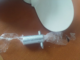
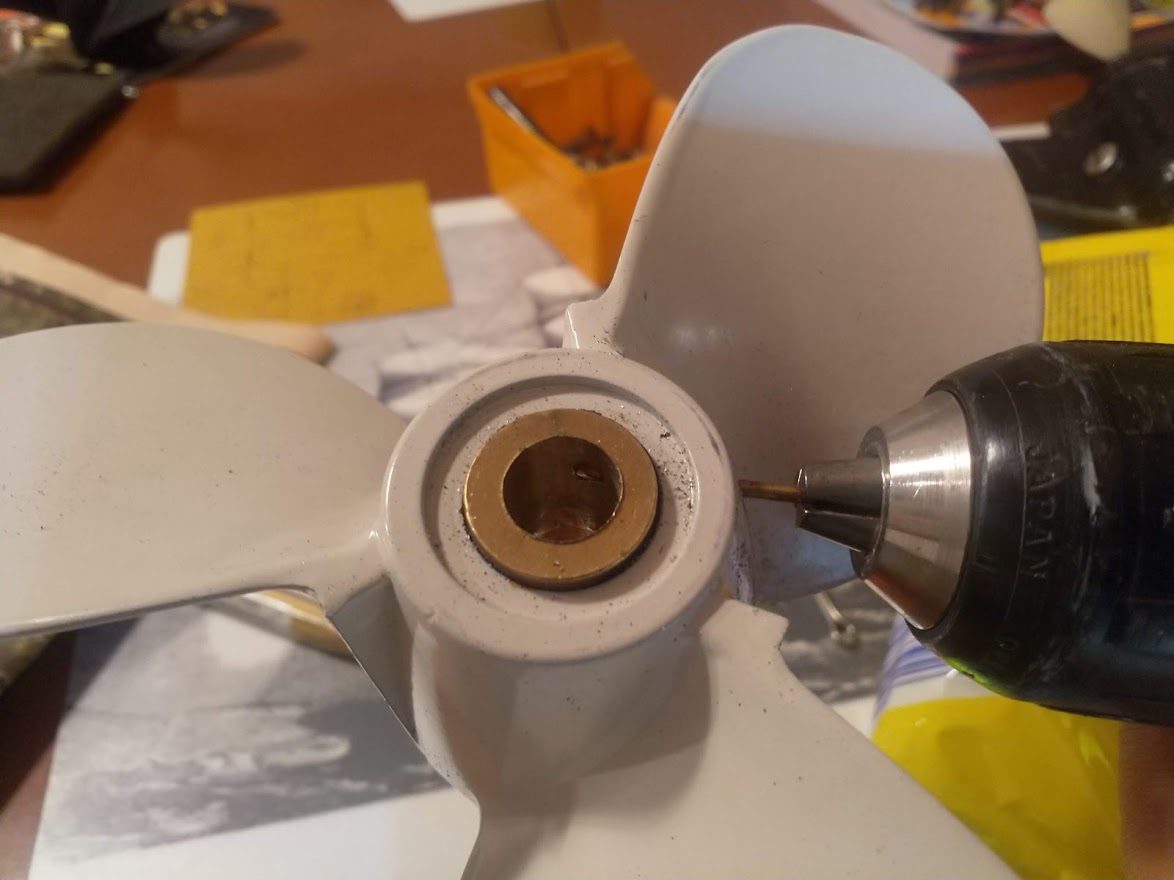
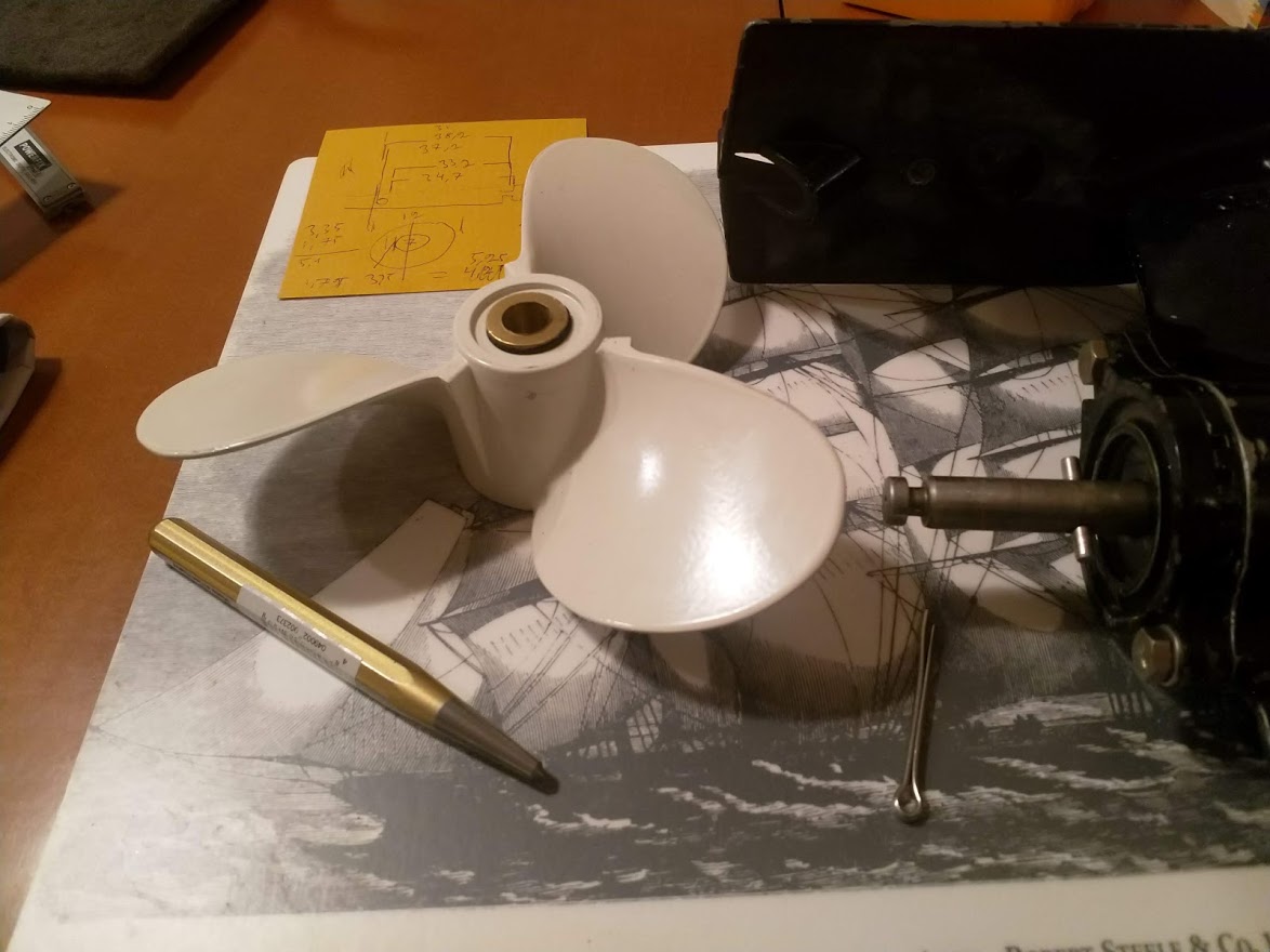
After a semi successful run at 22kmh will continue the rehearsal. This motor have 1/2.15 gear, will now try with similar but with 1/1.85 gear, should be faster… Here preparations for doing the yamaha prop compatible to Tohatsu shaft . Will fill the hub with JB weld marine, hope its strong enough. Had a package that was unusable, to stiff( dated 2017) but heated the resin tube in water, got it somehow workable again. Used a 12mm alu shaft and drilled a hole for the pin to use as a plug. Hope will get it loose:) after the JB has hardened, only protected by thin film… Have high hopes for the 8 pitch Yam propeller, not sure 3.5hp is enough to get full rpm for it though.

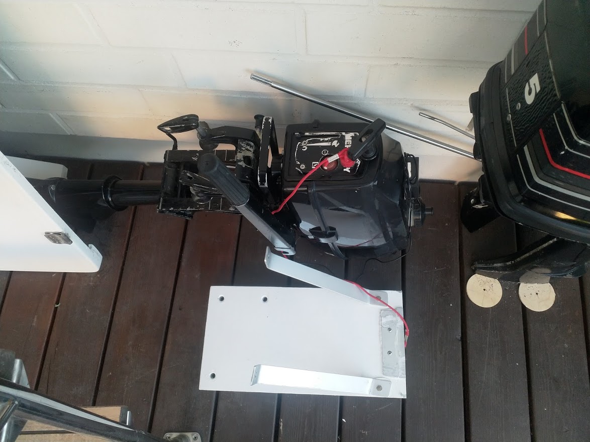
To minimize the risk of ventilation did cut the transom another 6mm, can always lift the engine case needed. A word of safety, in the background the other 3.5 hp test motor, it did not have a kill switch lanyard, added one, would be extremely foolish doing even a short test without. If can not achieve speeds closer to 30 kmh wit this, will use the 5 hp motor, that will for sure go 30+ but the weight is already 21 kg and high, will be a handful to handle… Guess as using twin 6384 on the e version, that will be comparable to 5 hp 2stroke
.
Do you have a link to that 2 blade propeller?
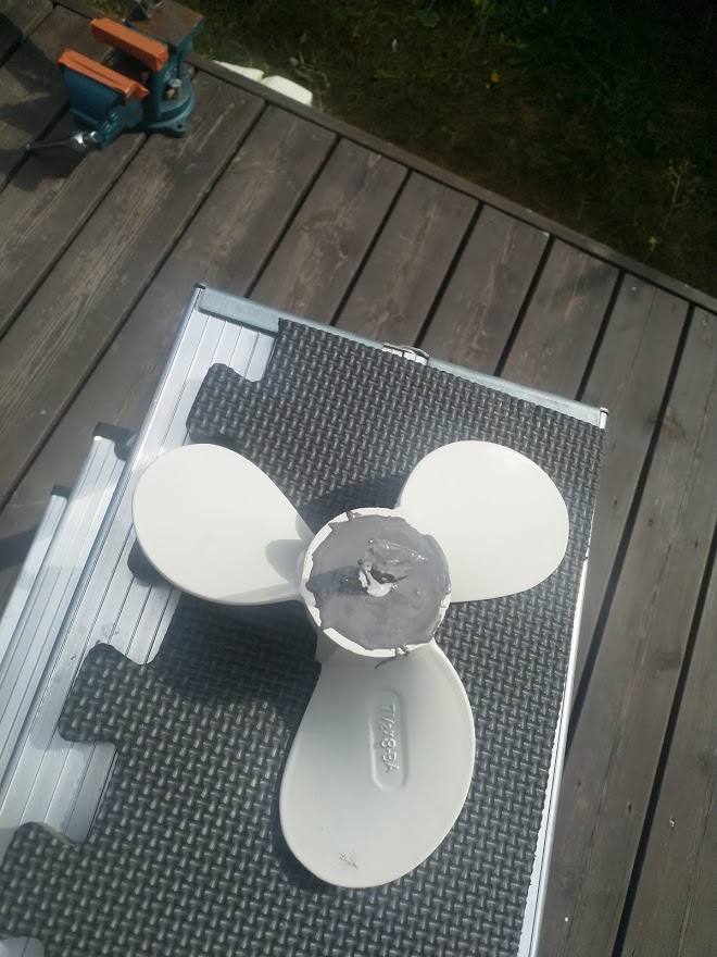
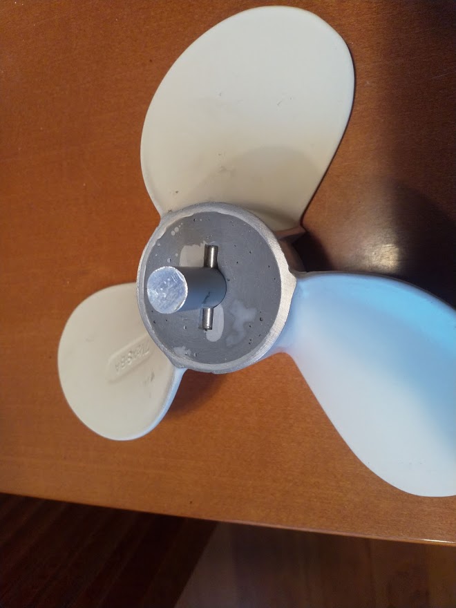
Unfortunately not. Its a pretty old Japanese prop, manufactured long before internet time. Not available anywhere, did not even find a picture on the web. After checking, believe pitch is close to 7, diameter is 172 mm. Relative small blade area compare to any of the 3 blade standard props, but worked well in this application. Possible would work rather economically on a efoil also? Some comparison can be made little later, i have the Flite prop… On a surf though, its little different as no foil. If promising maybe worth scanning to digital format if someone has such equipment?
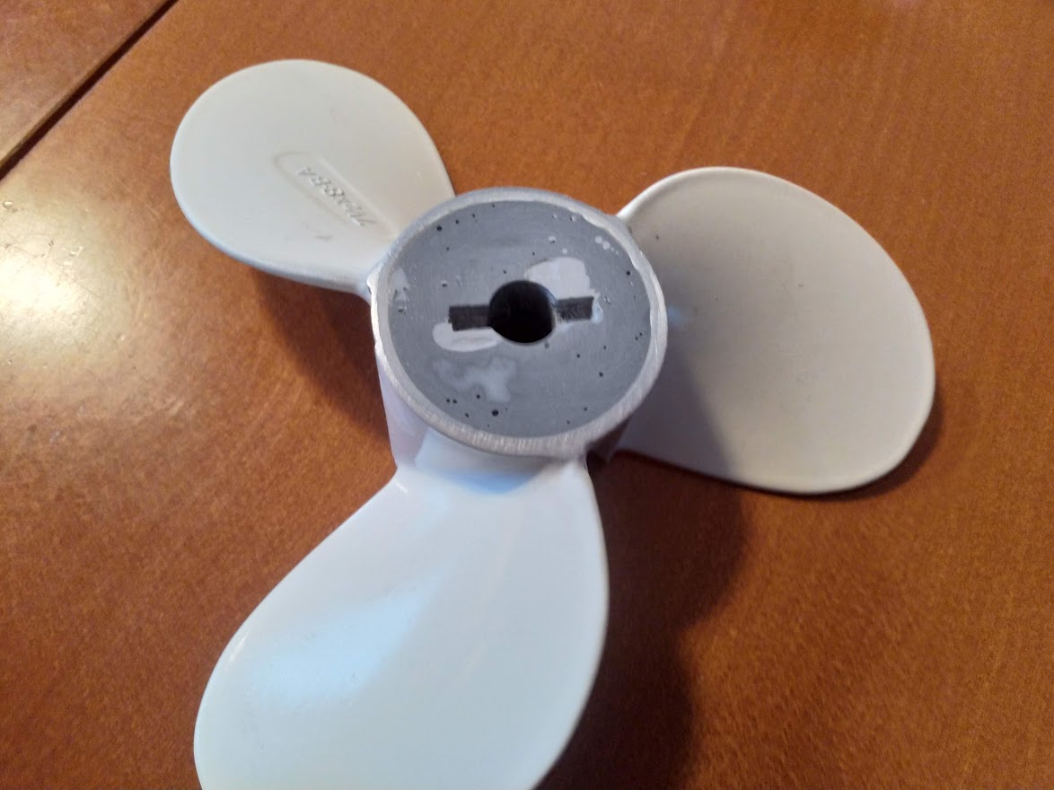
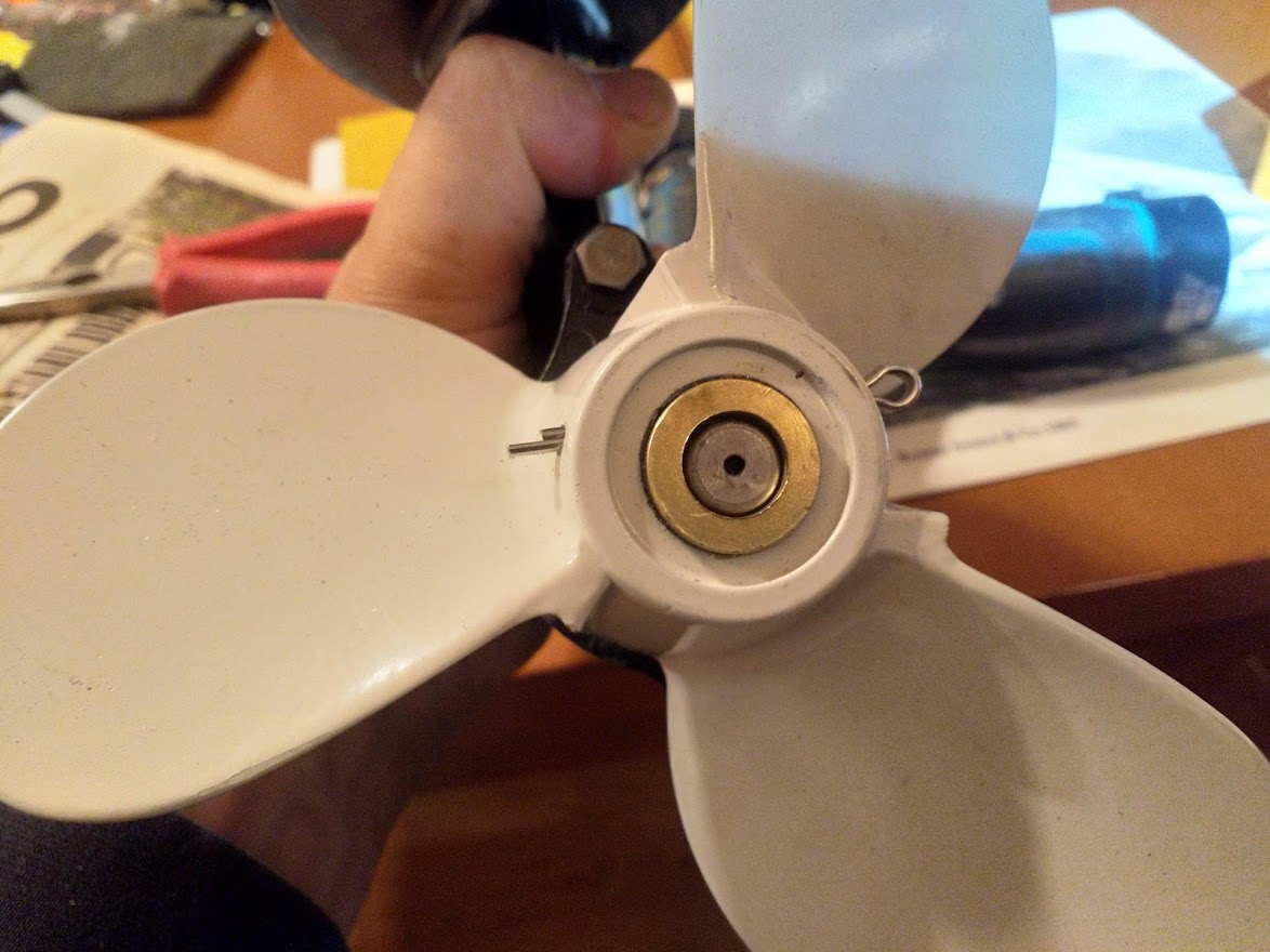
Now we have a Yamaha clone that fits a Tohatsu 12mm shaft and pin. Made a mistake when banging out the plug so needed little additional filler to fix that but should be OK now. Don’t know will the JB weld hold up for 3.5 HP but guess its hard as any plastic so why not? Need still to drill the hole for the cotter pin keeping the propeller in place…not the easiest spot to drill( no straight surface and off center) but hope it will be ok.
Next test Sunday morning.
After some careful measuring crossed my fingers and started drilling, probably one of the most scary free hand drilling’s have done. The stars was in the right position this time… so to my big surprise the new hole is located pretty much spot on, not sure would like to repeat this…only loss was two 2 mm drill bites, did not even drill my leg:)
So had further test runs today. The idea was to test the 2 blade and the Yamaha clone with the motor having 1/1.85 gear. The good thing was that the modified Yamaha propeller as such worked on the outboard, and it was immediately noticeable that blade area and pitch is higher, much higher speed on idle. The bad thing was that the outboard suffered some technical problems, was not running properly under load, so unfortunately had to change motor back to the Tohatsu with 1/2.15 gear. So put the 8 pitch Yamaha prop on that one instead. All fine, engine had to work harder to spin that prop, but the propeller started to ventilate loosing grip totally at higher speed( when starting to plane). Transom is now 40 cm, so should be fine but the grip on these propellers are not that great( to say the least), so will continue cutting until get the Yamha to work properly. The disadvantage of shorter transom is obviously more drag. Its interesting though that the 2 blade has much less ventilation issues than the 3 blade ones. Believe the hull shape is also contributing to the ventilation, a slight v would probably be much better, not to mentioned the rough shape of the gear case on these small motors. To be continued…
Is it called ventilation or cavitation?
That’s different things actually. Cavitation is very roughly speaking boiling of water around the propeller causing wear an tear of the propeller. A rapid loosing of grip/thrust is usually related to ventilating, propeller sucking air, loosing momentum /thrust. In this case the main problem is for sure ventilating due to various reasons.
Here’s a humble guy explaining ventilation VS cavitation without all the jargon:

New testing today, with 2 different 3.5 hp motors and 4 different propellers. Als tested different heights of the engine. In the end it looks like Tohatsu with 1/2.15 gear ratio was best suitable. No big difference to the 1/1.85 gear.
The Chinese Yamaha clone 7 1/2 X 8 - BA was a disappointment. I hoped it would perform better then the plastic Tohatsu props, but it was the worst propeller from ventilation point of view, very sensitive to trim. Also noted that it really need more torque than a 3.5hp can deliver. So what have been noted on e foils, in original diameter its very hard driven prop, not that great. Yamaha have a reputation of making rather good props, so wonder, is this a exact copy or just something looking like the orginal.
With this equipment best achieved was 21-22 km( 2 blade plastic), maybe not bad for a 3.5 hp , but still disappointing.
At this speed obviously the hull is planning but not very easy, think need to go at least 30 kmh to plan properly. Next stage will test the 5 hp… It does not sound like a big different but it is, not 100% sure the equipment will hold for that:) At least need to add som flotation in the stearn to counter the additional weight.
At the moment my estimation of power requirement for any fun is minimum 5 HP at the propeller shaft , guess with power losses in the e version close to 5kw in reality.
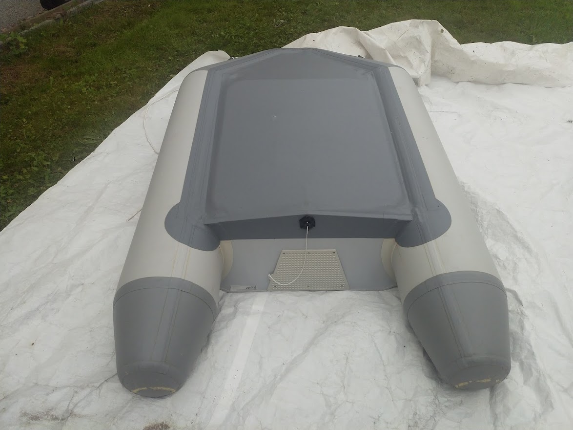
Got roughly the same speed with the small inflatable on the picture, except that the Yamaha clone was way to hard to turn, had to abort the test not to make a hole in the piston.
You need something like this ![]()

Wonder what is the diameter of power cables for that one 
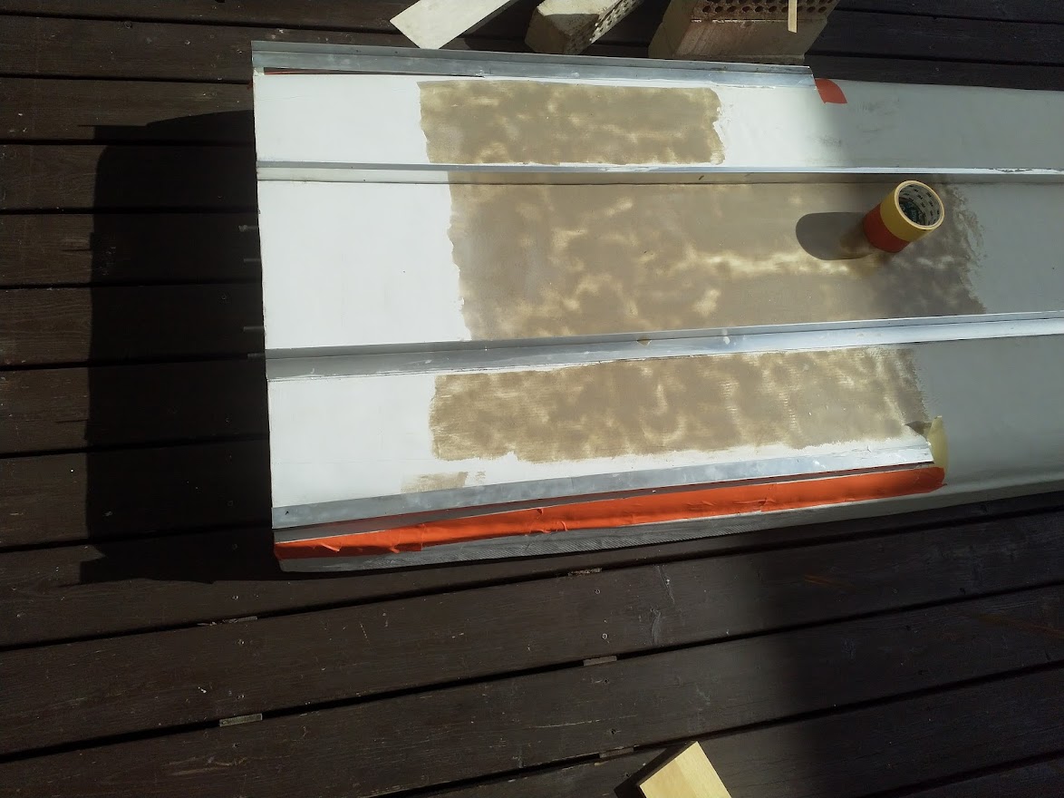
Added some rails just to test. I knew the location was not optimal but just wanted to test would they direct the water to the propeller resulting in having less ventilation. Well not much of a difference. And with the so far fastest 2 blade, top speed droped…
Anyway, as this was based on the shape of a inflatable sup, the stern is slightly narrower, and does not create enough lift for easy planing.
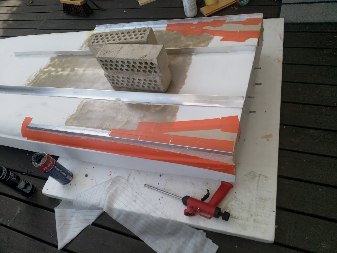
So now testing even more rails:) Shorter, just on the side and also making the flat partition of the bottom wider. These should hinder the water to escape on the sides. Pleas note the expandable foam used to fill the cavity ha haa… Will maybe cover that with tape or one layer of epoxy.
If having time will next weekend repeat the test with both the 3.5 and the 5 hp motor. It does not sound much but with this “stable” hull and 21 kg 5 hp will be a handful keeping upright. And expecting increased speeds also, if not braking 30 kmh will be severely disappointed. Water is getting pretty cold now so need to stay on the board !
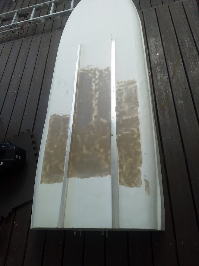
The brown stuff on the bottom is just epoxy putty. The surface was little uneven due to the build process and the hull was faired originally properly only the last 30 cm of the hull where the water leaves the bottom. The idea of this putty was to make it self even( epoxy resin, little thiotroph additive and brown silica or maybe its glass baloon’s, cant remember, lost the sticker)
It worked pretty well, as long as you have the board perfectly even this saves some sanding, gravity will do it for you, used a spatula to spread it out. Smooth or not, will have no measurable impact on speed so reason was only to test can such loose putty be used. Resin content is high though, so its hard to sand in case needed.
Work commitments killing my hobbies, to little time:) Anyway, will continue testing outboard version and hull modifications next spring…but meanwhile proceeding with the battery.
-
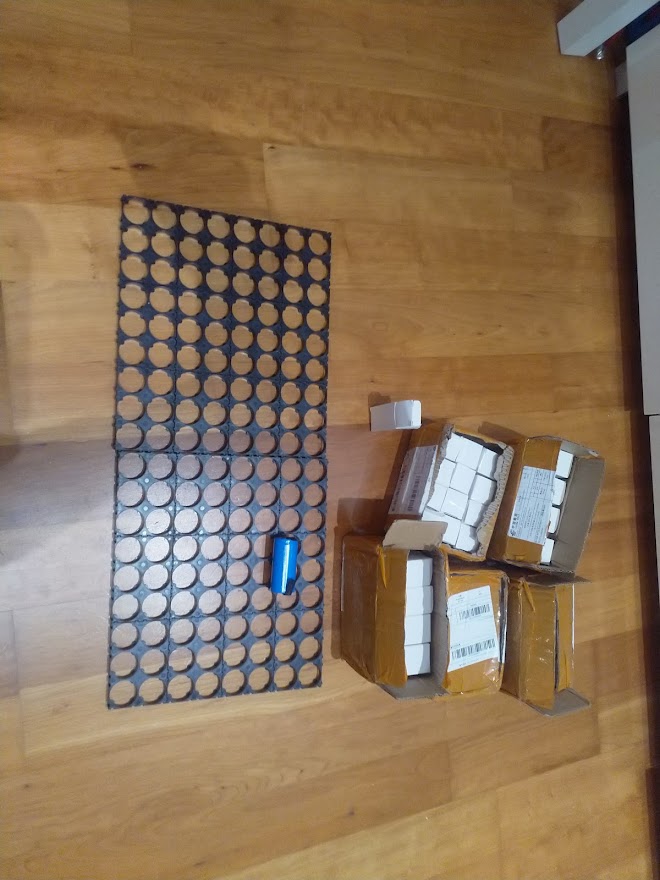
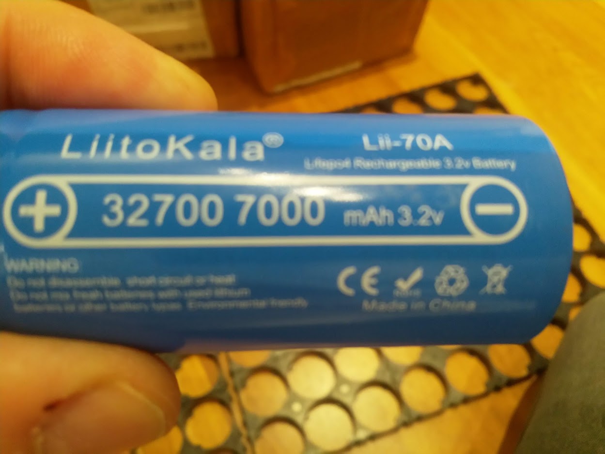
I have 60 of these cells.
-
I calculate 6 amp / cell.
-
guess can draw max 15 amp constant from them.
-
Battery will be 7s8P
-
so constant load only120 amp , 60 amp per motor & esc(2x 6384+ 2x Flycolor 150a 6s )
-
7s lifepo4, realistic voltage maybe 22v
-
so roughly 2650 w/3,5 hp ( minus losses in esc, wires, transmission ).
So actually will in reality have about the same power as the 3,5hp outboard, probably slightly less. That’s not much for a e surf, it will be slow…Will need a perfect hull and propeller to get it moving…engine power will have( 2 x 6384) but can not utilize much of that. Probably need to build another battery pack later, but lets start with this first.
Actually just found a you tube test, it looks like they can do close to 25 amp, that would mean about 4400 w max power that’s much better! Need to think about how to cool the batteries also.
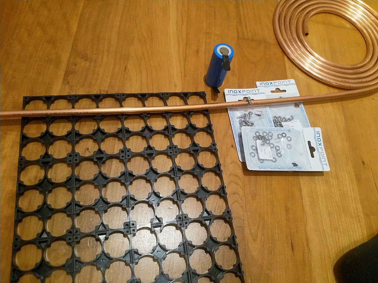
These cells has the nickel strips welded on from factory, my initial idea is to connect them with a copper bar, soldering or then a mechanical securing( SS bolt). The copper used in household water pipes is very pure, wonder would that work in this application?
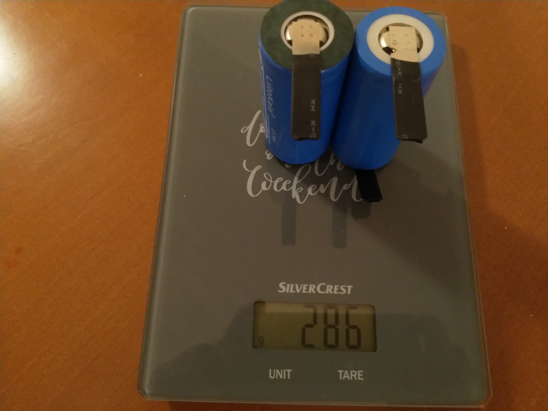
Weight of the cells is about 143 g each, pretty much as per specification. Will tomorrow buy the copper pipe and SS bolts and nuts, maybe m4 or m5. Will first do the top balancing as 8P1S. Will probably do only 8 cells at a time so it will take some days,…all winter time though.
The plan is to cut the soft copper pipe in to the length of 8P pcs. Then flatten the pipe with a hammer or something. Then drill 4M holes in the nickel strip of the battery and same size hole to the “busbar”. The strip will be attached between the busbar and a copper washer with 4m stainless bolts. No soldering.
Will this work?
Should work although a bit unconventional but what in here isn’t?!?! Why not just use Copper Tape in that case or else Copper Earth Strap?