That’s different things actually. Cavitation is very roughly speaking boiling of water around the propeller causing wear an tear of the propeller. A rapid loosing of grip/thrust is usually related to ventilating, propeller sucking air, loosing momentum /thrust. In this case the main problem is for sure ventilating due to various reasons.
2 Likes
Here’s a humble guy explaining ventilation VS cavitation without all the jargon:

2 Likes
New testing today, with 2 different 3.5 hp motors and 4 different propellers. Als tested different heights of the engine. In the end it looks like Tohatsu with 1/2.15 gear ratio was best suitable. No big difference to the 1/1.85 gear.
The Chinese Yamaha clone 7 1/2 X 8 - BA was a disappointment. I hoped it would perform better then the plastic Tohatsu props, but it was the worst propeller from ventilation point of view, very sensitive to trim. Also noted that it really need more torque than a 3.5hp can deliver. So what have been noted on e foils, in original diameter its very hard driven prop, not that great. Yamaha have a reputation of making rather good props, so wonder, is this a exact copy or just something looking like the orginal.
With this equipment best achieved was 21-22 km( 2 blade plastic), maybe not bad for a 3.5 hp , but still disappointing.
At this speed obviously the hull is planning but not very easy, think need to go at least 30 kmh to plan properly. Next stage will test the 5 hp… It does not sound like a big different but it is, not 100% sure the equipment will hold for that:) At least need to add som flotation in the stearn to counter the additional weight.
At the moment my estimation of power requirement for any fun is minimum 5 HP at the propeller shaft , guess with power losses in the e version close to 5kw in reality.
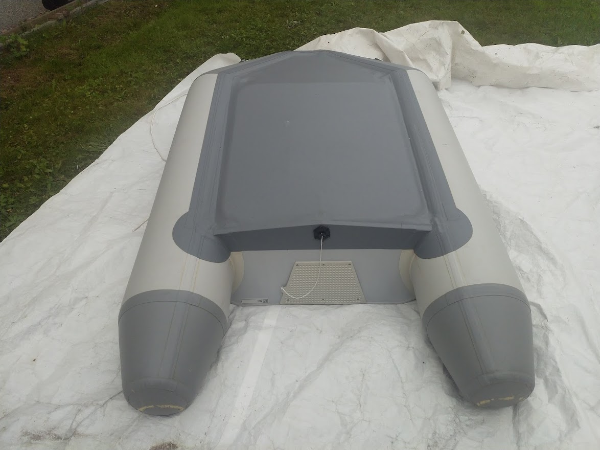
Got roughly the same speed with the small inflatable on the picture, except that the Yamaha clone was way to hard to turn, had to abort the test not to make a hole in the piston.
1 Like
You need something like this ![]()

1 Like
Wonder what is the diameter of power cables for that one 
1 Like
Added some rails just to test. I knew the location was not optimal but just wanted to test would they direct the water to the propeller resulting in having less ventilation. Well not much of a difference. And with the so far fastest 2 blade, top speed droped…
Anyway, as this was based on the shape of a inflatable sup, the stern is slightly narrower, and does not create enough lift for easy planing.
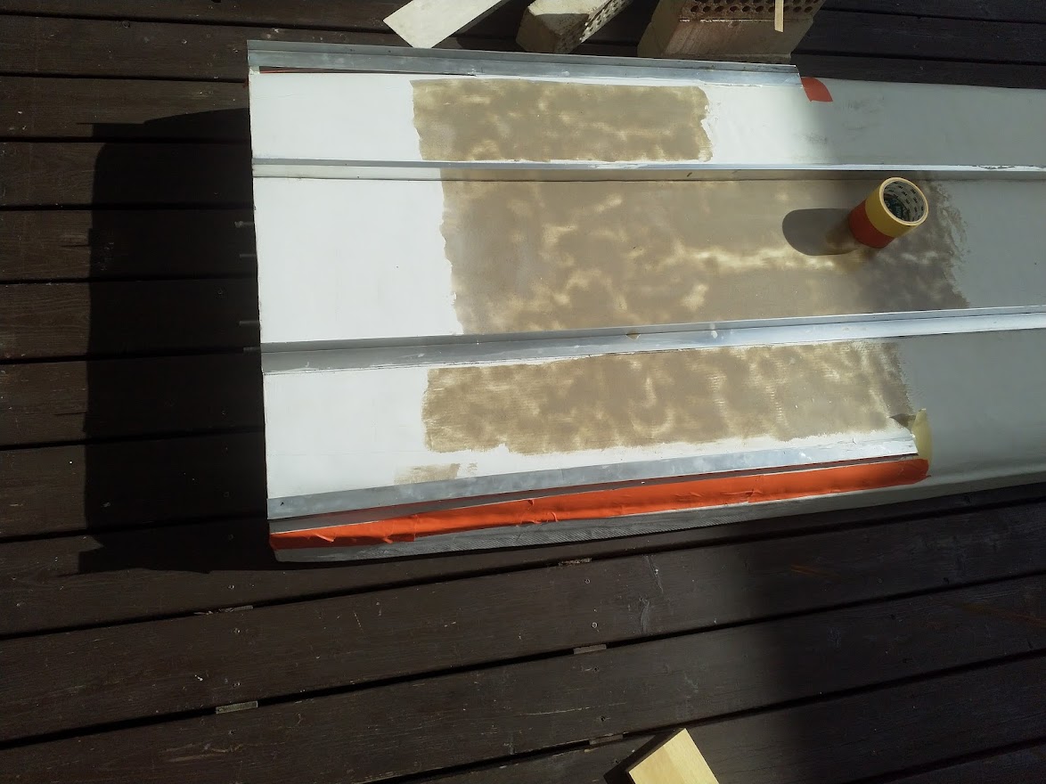
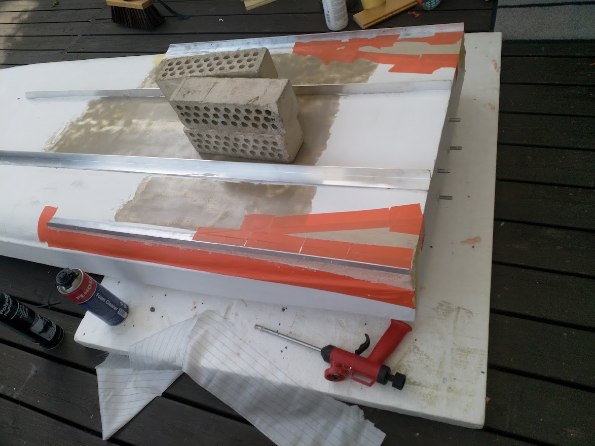
So now testing even more rails:) Shorter, just on the side and also making the flat partition of the bottom wider. These should hinder the water to escape on the sides. Pleas note the expandable foam used to fill the cavity ha haa… Will maybe cover that with tape or one layer of epoxy.
If having time will next weekend repeat the test with both the 3.5 and the 5 hp motor. It does not sound much but with this “stable” hull and 21 kg 5 hp will be a handful keeping upright. And expecting increased speeds also, if not braking 30 kmh will be severely disappointed. Water is getting pretty cold now so need to stay on the board !
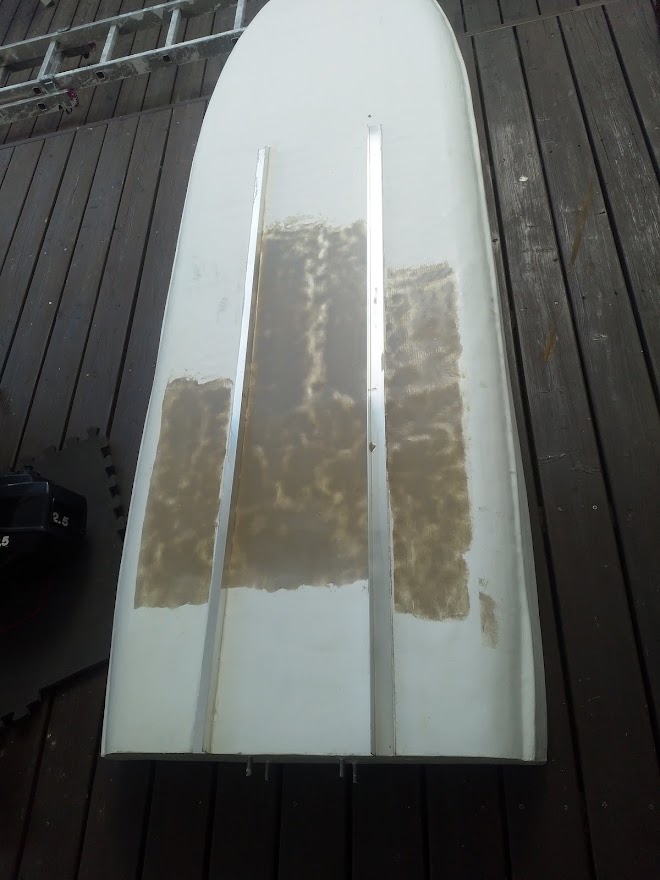
The brown stuff on the bottom is just epoxy putty. The surface was little uneven due to the build process and the hull was faired originally properly only the last 30 cm of the hull where the water leaves the bottom. The idea of this putty was to make it self even( epoxy resin, little thiotroph additive and brown silica or maybe its glass baloon’s, cant remember, lost the sticker)
It worked pretty well, as long as you have the board perfectly even this saves some sanding, gravity will do it for you, used a spatula to spread it out. Smooth or not, will have no measurable impact on speed so reason was only to test can such loose putty be used. Resin content is high though, so its hard to sand in case needed.
1 Like
Work commitments killing my hobbies, to little time:) Anyway, will continue testing outboard version and hull modifications next spring…but meanwhile proceeding with the battery.
-
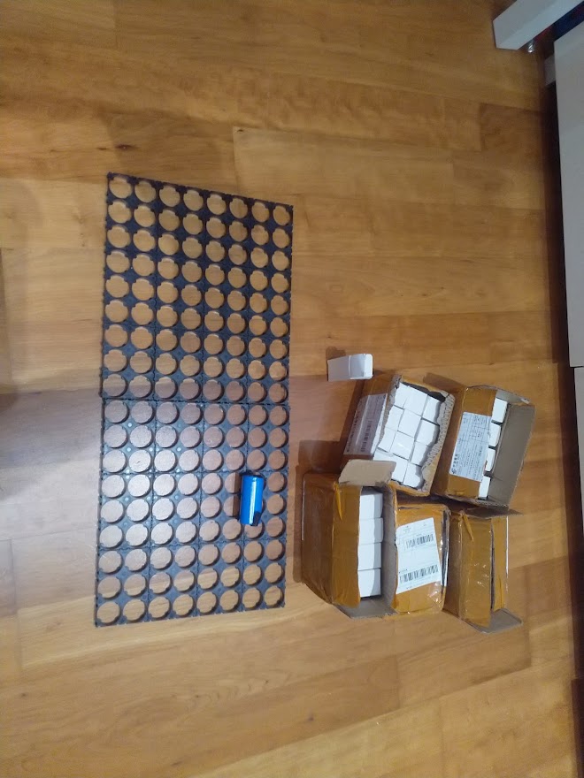
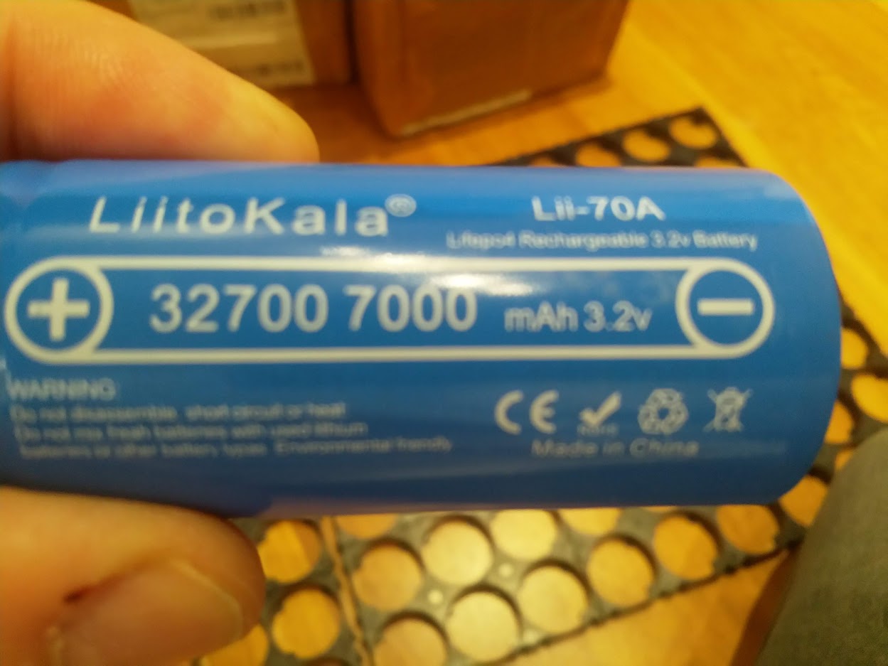
I have 60 of these cells.
-
I calculate 6 amp / cell.
-
guess can draw max 15 amp constant from them.
-
Battery will be 7s8P
-
so constant load only120 amp , 60 amp per motor & esc(2x 6384+ 2x Flycolor 150a 6s )
-
7s lifepo4, realistic voltage maybe 22v
-
so roughly 2650 w/3,5 hp ( minus losses in esc, wires, transmission ).
So actually will in reality have about the same power as the 3,5hp outboard, probably slightly less. That’s not much for a e surf, it will be slow…Will need a perfect hull and propeller to get it moving…engine power will have( 2 x 6384) but can not utilize much of that. Probably need to build another battery pack later, but lets start with this first.
Actually just found a you tube test, it looks like they can do close to 25 amp, that would mean about 4400 w max power that’s much better! Need to think about how to cool the batteries also.
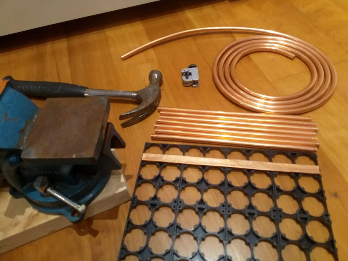
These cells has the nickel strips welded on from factory, my initial idea is to connect them with a copper bar, soldering or then a mechanical securing( SS bolt). The copper used in household water pipes is very pure, wonder would that work in this application?
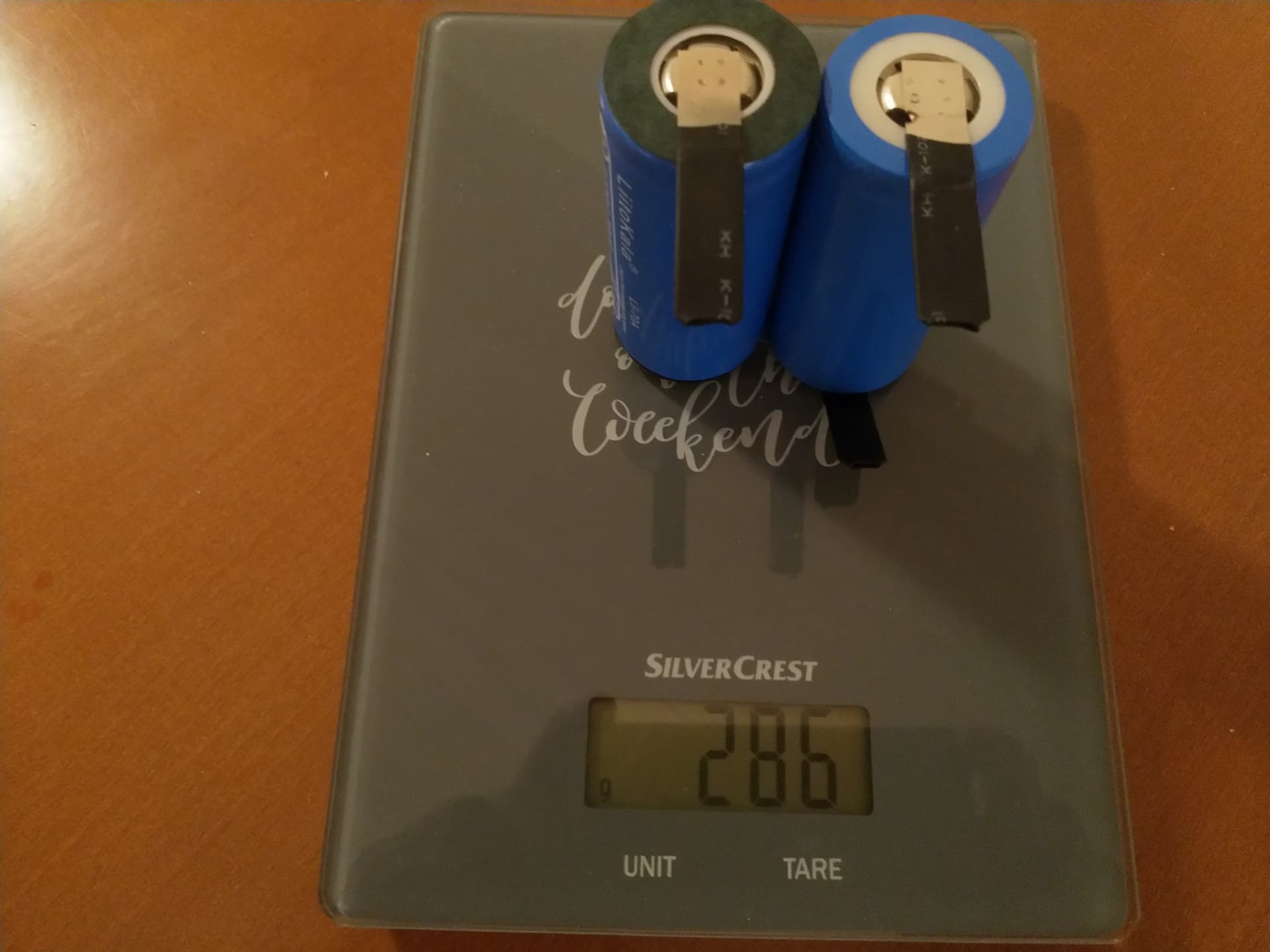
Weight of the cells is about 143 g each, pretty much as per specification. Will tomorrow buy the copper pipe and SS bolts and nuts, maybe m4 or m5. Will first do the top balancing as 8P1S. Will probably do only 8 cells at a time so it will take some days,…all winter time though.
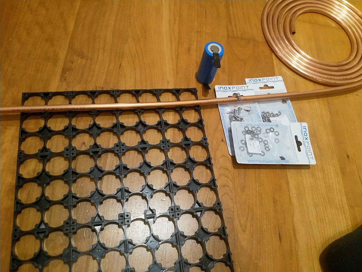
The plan is to cut the soft copper pipe in to the length of 8P pcs. Then flatten the pipe with a hammer or something. Then drill 4M holes in the nickel strip of the battery and same size hole to the “busbar”. The strip will be attached between the busbar and a copper washer with 4m stainless bolts. No soldering.
Will this work?
Should work although a bit unconventional but what in here isn’t?!?! Why not just use Copper Tape in that case or else Copper Earth Strap?
Thanks for You comments. Yes for sure its a bit unconventional, fits fine into this project:) as it will be a bit different in many aspects. The positive thing, if it works like intended, the pack will be totally dismantlable, cell by cell. The copper tape in your link would have been perfect, the flattened pipe will be about the same specs so only little more work to achieve the same(and can be sourced almost anywhere).
The plan is to to fill the the main positive and negative busbar/pipe with the power cable and solder it, this way i hope it can handle the serious amps that will be needed. Guess this about 48 amp battery will only be good for 15-20 minutes so will now check the cost for another 60 cells. I got lucky last year, the first batch of 60 cells was less than 200 USD delivered to EU.(shipped in lots of 12 pcs). All cells was OK, so will continue to order directly from LiitoKala. Now the price will be much higher unfortunately.
1 Like
…flattened copper tube as a busbar, nickel strip connecting cells, cells that can be assembled and disassembled. …it sounds like the described approach is similar to the “batt-o-matic” design:
Yes?
I’ve been working on something similar. I have the battery sleeves, trays, and lids printed. Though, I’ve not assembled the busbars and nickel strips; so I’ve not connected and tested the packs.
I’m interested in your findings.
Hm… first try… back yard engineering ha ha. About 2.6 mm thick, 14mm wide, probably enough for a busbar. Think this copper is about 99,8 % pure so should work, at least until it will touch salt water:)
3 Likes
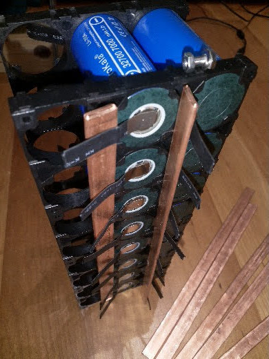
Playing with the idea how to position the busbars…if keeping them in 90 degrees would be very simple to secure the nickel stripes on each side with the ss screw/bolt. On the other hand, somehow feels safer to keep them flat against the battery. Then need flathead bolts/ machine screws, flush with the busbar on the battery side, and somehow need to lock the screw so it does not turn when tightening the nuts. M4 x8 or 10mm will do i guess. There is one flaw by using this type cells with nickel strips…the one on the positive and negative should be positioned to different directions, but it is what its now…
1 Like
Ordered some 60 additional cells from AliExpress so now will have 7s16p battery for the summer. Price was due to the EU tax higher than previous, but frankly speaking, I don’t mind. I think its better in the long run that competition is equal for all web shops and also hope that AE will start using EU warehouses, that should improve shipment times as also warranty/customer service.
Happy to see that the UK based company Easy Composites has now opened an EU based shop, https://www.easycomposites.eu/ . IMHO good value and reasonable shipping costs.
1 Like