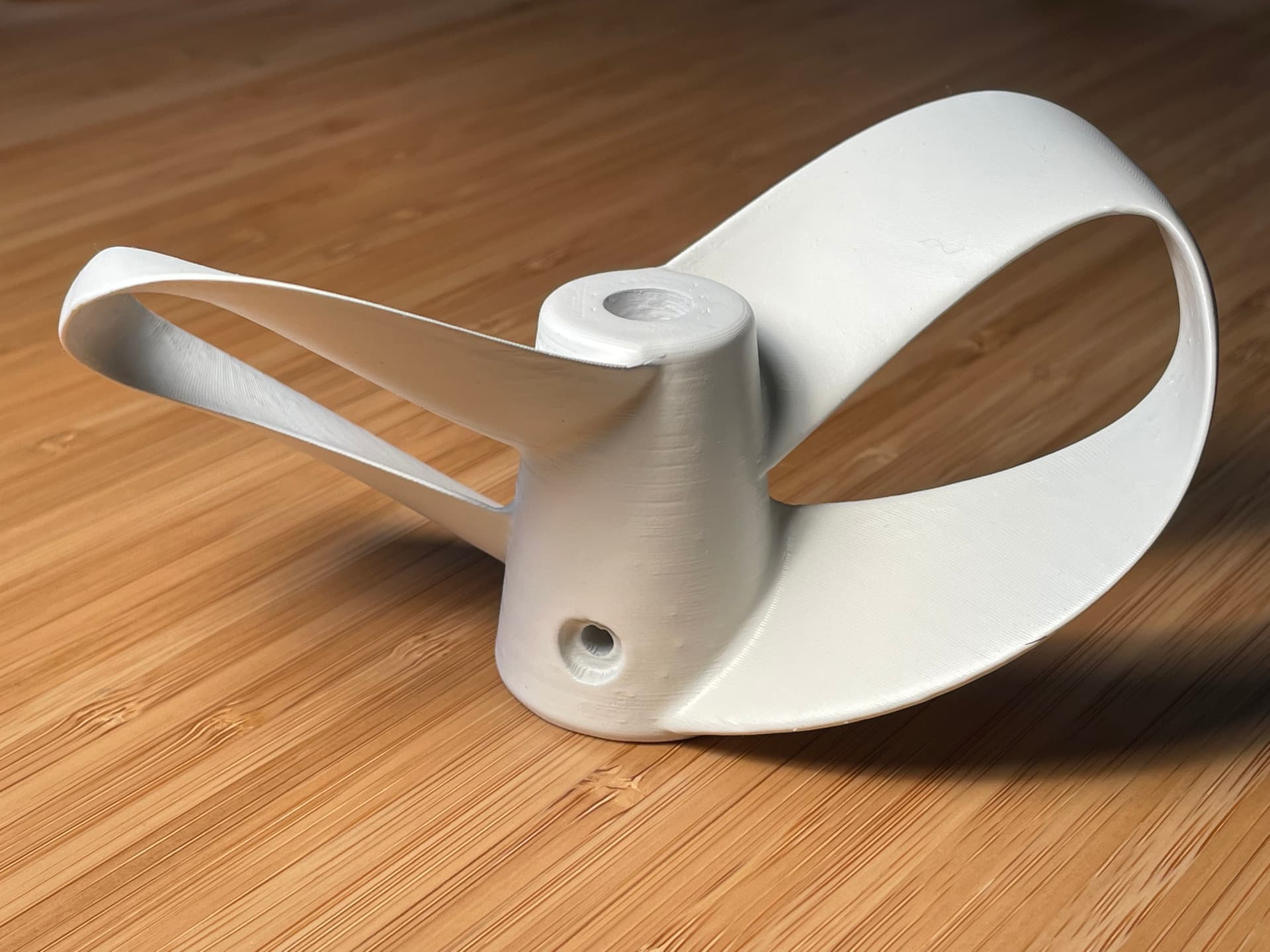
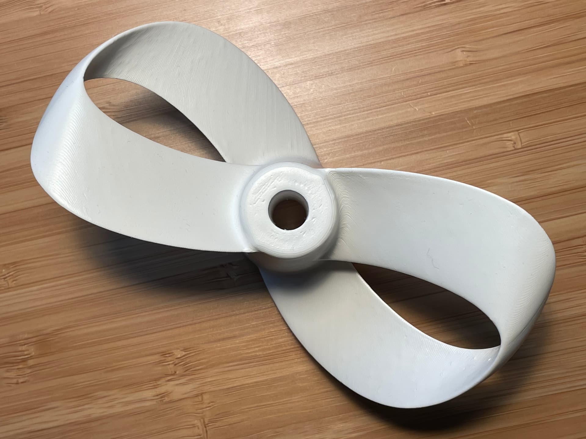
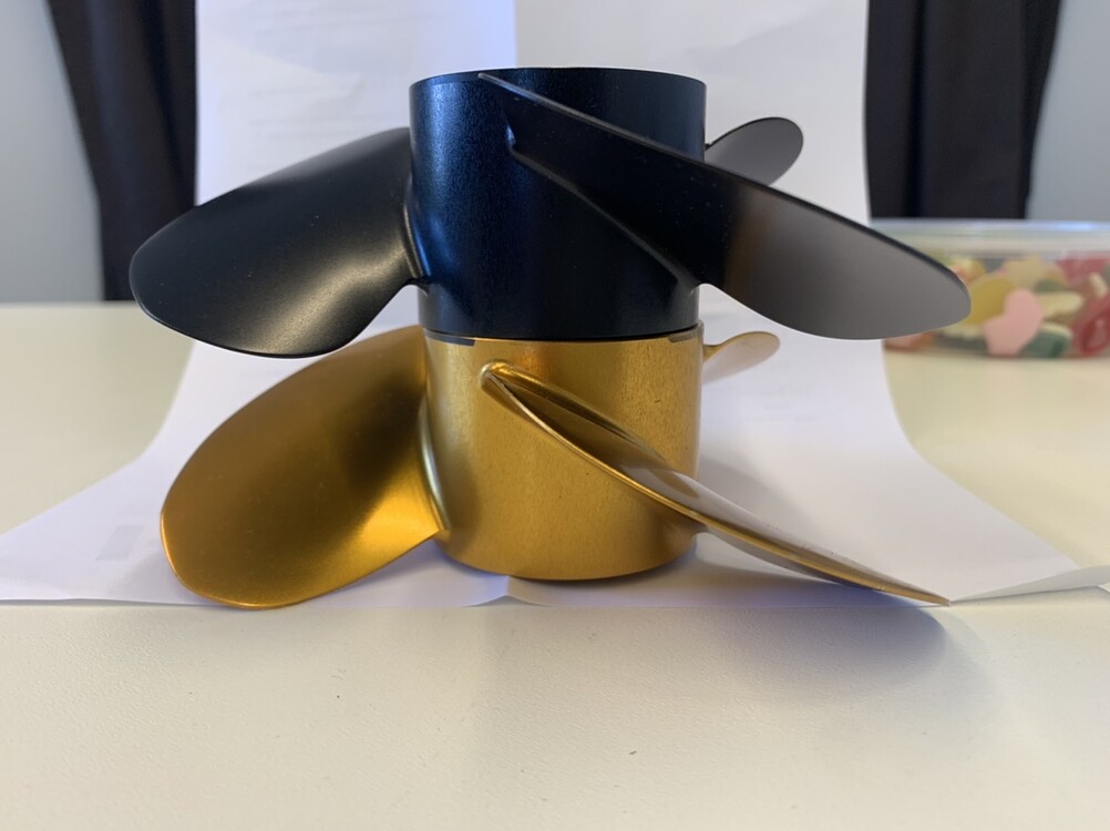
I did another variant of the loop prop, i thought my last one looked OK but the hub was too long, really happy with this one. Now if only i had a metal 3d printer 
2 Likes
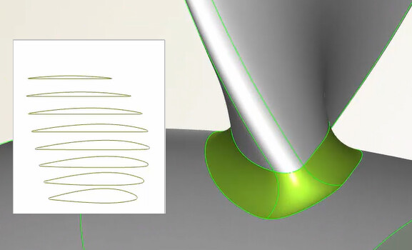
I can see you’ve thickened the blade roots on the hub (called filets) as seen on the CAESES site
Ship Hull Design with CAESES › CAESES. Oddly enough, the site recommends thickening the profiles as follows…
but their best optimisation - the FR prop - has thin blades with minimized roots and filets…
![]()
It is possible to print that with an SLS printer in PA12?
Or do you think that the blades are to thin for this material?
While it’s all fun and games with these designs. You really need to print a normal prop with similar pitch values to see how the sharrow version compares.
Yes, but such a propeller looks sexy on our diy efoil 
Thats my plan. I already printed and compared a lot of props. The differences are not that big as you would imagine. Its really hard to test in a way that the results are accurate enought to see differences at all. No wind, no water movement, riding at exact same speed. Even then the data from the VESC are only within plus minus 5-10% error margin. The only method getting better results is static thrust test. But its only for static thrust then  and also the Motor current data (= motor torque) from the VESC is too noisy to make good use of. (jumps like 10A up an down)
SLS can print anything
Because the bending moment is higher closer to the HUB
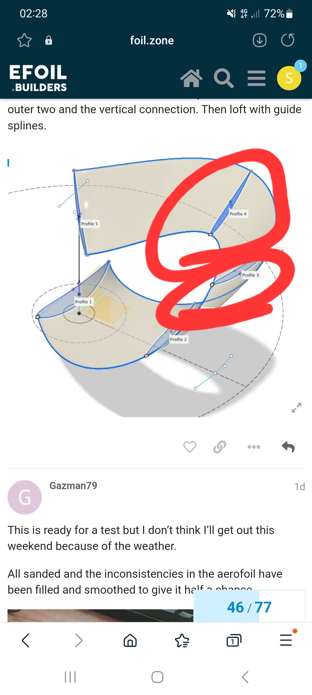
No, just a closed spline with four points. Modeled to a sharp trailing edge. Max thickness at 50% and a little chamber adjusted to the position on the blade
2 Likes
The thickening recommended by caeses is mainly for strength, not for efficiency. Props break if not designed properly for the load but the FR prop is a tank when compared to its use.
I filleted since this will be done in 3d print with carbon overlay so the fillets give the root some support and it’s easier to get the fabric to follow the shape
It’s too thin as it is now, to be able to print and use with sufficient strength the blade needs to be thickened by a millimeter or so even when done in nylon SLS.
It was intended for carbon overlay but when i look at the thinnest section it might be too thin for my 3d printer to get right, the extruder is not the best.
Easy to fix in the model though, once the base geometry is good it’s easy to do updates.
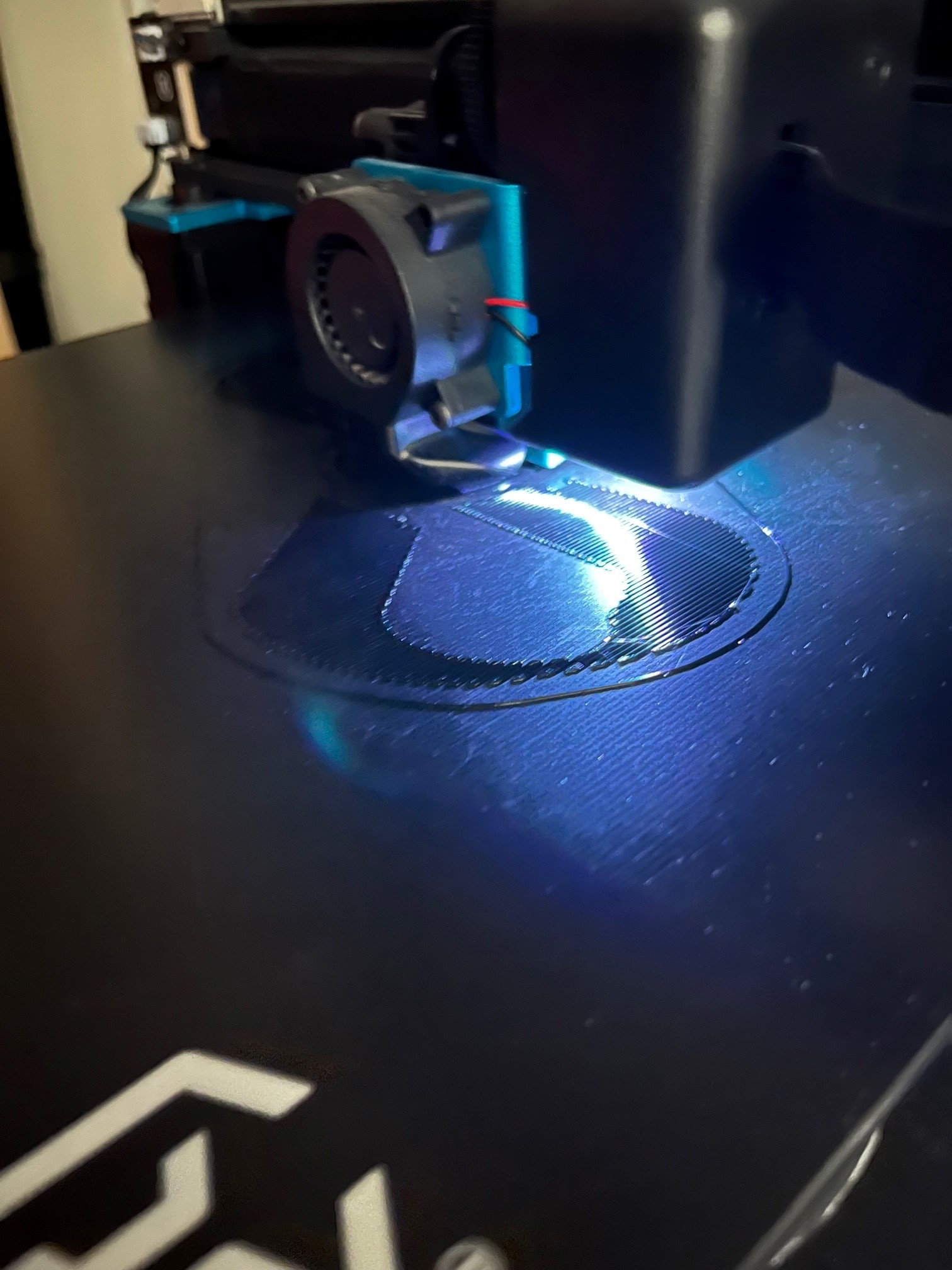
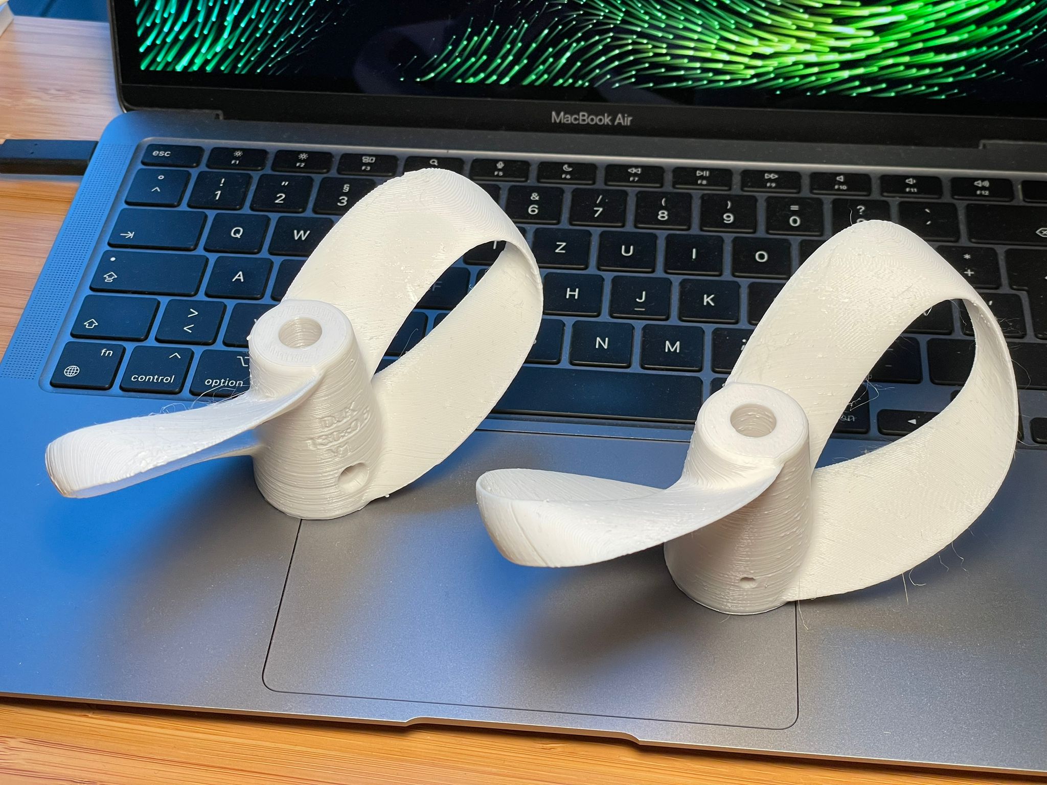
My third is just done. 2.5h
First one already sanded, fillered and painted.
When the top and bottom wing overlap, its really a pain to sand it. So my third one has no overlap. We’ll see.
1 Like
There are some factors that I do not understand and needs to be clarified:
Diameter and pitch of the propeller is designed like any other but:
- should the leading and the trailing blade have the same pitch? (Sharrow seam to have more pitch on the leading)
- should each blade have the same pitch on the inside as on the outside?
- should the vertical profile connecting the blades be in neutral position or pushing in or outward? (Sharrow’s seam so push outward)
- should the vertical section be same chord lenght or minimized?
On all this thought one has to remember that the water does noch enter the prop directly from the front, but from an slight angle depending on the actual speed difference between the movement of the device and the stream velocity of the propulsion. E.g. when in static thrust, the angle is maximum and the water enters even from the sides.
I come from airplanes and so I think I know that the trailing blade should have more pitch then the trailing (opposite to sharrow’s design). This is because the trailing airfoil is in already redirected air from the front airfoil. But maybe they intend something else with that?
I am sure you guys have more practical experience than me. But my thoughts can help you, as brainstorming content. Sharrow says that there main advantage come from that sharrow propeller has no slip. If you can explain where the slip technicly come from, there is to look at, why a normal propeller got slip and the sharrow not. The roundings outside put extra water to the middle of the blades from the sides. The Extra water is the main focus I think. If this effect does not happen you can do what you want with the blades itself.
Surely the sharrow has slip, it works in a flowing media, not in a solid.
The loop reduces the tip vortex, one of the same benefits of two blade props over three blade. If done correctly the loop should also increase the pressure on the low pressure side of the prop, decreasing cavitation and flow separation. It’s a balance of that and drag.
Some of the basic rules should still apply: as low wetted surface as possible while still maintaining the right thrust and flow, no form drag in places where it doesn’t add thrust. Here the balance point is hard (impossible) to find without a CFD program to simulate the flow…
Physic says “No”. Thats actually not possible. Maybe they mean something else.
Also one thing to keep in mind is the difference between:
- Propeller efficiency = stream power / shaft power (never zero!!)
- Propulsive efficiency = populsion power theoretical needed / Shaft power (normally zero in static thrust and high at cruise)
I guess that the Sharrow prop has had to compromise a lot for ease of manufacturing so not all of the design is driven by performance.
When it comes to the vertical profile i have tried to make my prop neutral to avoid form drag. It will anyway create a wall for slipping water going towards the tip. Then for how much chord is optimal… as little as possible that still does the job 
1 Like
I’ve downloaded SimFlow and have been playing with it a little bit, so maybe that will be a useful CFD comparison tool once I learn it a bit better. It seems like it could do what we want, but the node limitation and single thread processing for the free version will make analysis take a while.
The longer I think, the more I am sure that this is the difference. Physics say “yes”.
Put a little vine in me, so I am creative. Put a little creative in me so I need a vine.  Good night guys.
Looking forward to the next step and the first results. Does anyone can say when he comes on the water for proofing theoretic themes.
2.5h is impressive, i don’t think i can get down to that with any kind of parameters on my printer.