I’ve been reading this forum for over a year and only just starting on my build now (because I also have young kids so not much spare time), so that’s a great way to build a solid understanding before getting into it! I’ll try here for you as a basic starting point, and also writing this in hope that if I have something wrong, it will get corrected by others.
It starts with working out how much power is required to give you enough pull to get out of the water, there are heaps of variables involved here, especially with single or dual motor, prop design and number of blades etc but from what I’ve read, about 4000W of power will be needed.
The battery is usually made up of individual cells in a X series Y parallel config (XSYP). This is how you get the desired voltage you need. A single battery cell has a Max voltage (fully charged) and cut-off voltage (fully discharged) and a nominal voltage (the one printed on the packet). Voltage drops as batteries become discharged. Li-ion batteries ‘nominal’ voltage are ~3.6V each and Max voltage of 4.2V, so if you do a 10S (10 cells in series), that creates a ~36V battery. The charger for this 10S pack would supply 42V, because this is the voltage required to reach max voltage for the pack. Most Boogie builds on here are 12-14S, so voltages 43-50V.
The number of Cells in Parallel contribute to the total current you can draw from the battery, effectively ‘sharing the load’ of the power delivery over more cells means less stress on each cell. In addition to this, the sum of each cell capacity makes up the total battery pack capacity. More cells = more foiling time per charge. The cell itself has a max discharge current, and it’s important to use high discharge cells, because for a boogie to pull you up out of the water, it’s needs a 5-10 second burst of really high power. On a basic level, to get 4000W at 36V, you will need ~111A. I had a 10S11P commercial battery pack (Stihl AR3000) that I was going to use but after seeing the cells inside were Samsung 29E, they only have 5A discharge, so 5A x 11 cells is only 55A. Compare the Cell output of the Molicel P45A which has a discharge rating of 45A, a massive difference in power delivery. You also want to overspec the battery pack so pulling less current than it is capable of delivering in order to not heat it up too much (Heat kills batteries).
BMS is Battery Management System, because battery cells are ‘dumb’, they don’t have any function to know when they’re too high or too low, usually the BMS controls the charge and discharge of the cells in order to prevent over charge or discharge, BUT because of really high discharge required for boogie, BMS is often only used to charge, and the ESC is relied on to stop batteries from getting too low. BMS usually also come with a balancing function which have a connection in between each cell set connected in series to check expected voltage against actual voltage and supply charge current in a way that evens up the cells.
The battery then supplies power to the ESC (Electronic Speed Controller). This is the ‘brains’ of the operations, because it also takes on the instructions from the remote receiver (Rx), and sends the power to the motors. It is usually configurable so you can set plenty of variables such as ramp-up power, temperate controls, and cut-off voltage etc. Note here, remote = Tx (Transmitter).
ESC’s can get hot, so need to be cooled, and because we operate these tings in water, it’s not so simple to keep them cool.
Cables, AWG is often used to refer cable thickness so you can look that up separately. More current needs thicker cables. If you use too thin a cable, they will heat up, wasting energy, and in extreme cases melting the casing even melting solder which is very dangerous due to the risk of a short (circuit). In general, the highest flow of current will be between battery and ESC, and it seems 8-10 AWG is common on the Boogies here. The connection plug need to also handle the current, that’s where your XT90 or QS8 comes into play (edit: good idea to use the anti-spark versions of these connectors). Sometimes because the BMS is used for charge only, you’ll also do an XT60 connection for charge only, as charge currents should be kept lower to avoid heat issues, just a few amps for charging.
The Receiver board needs a much lower voltage to operate (Usually 5V), so the most common way to supply power to the Rx is to use another chip called a battery eliminator circuit (BEC) which has the sole job of reducing voltage to supply the Rx. Some ESC also have a built-in BEC, but not the ones commonly used with Tow Boogies.
Then there is kv (Constant Velocity) ratings on the motors. These are Brushless DC motors (BLDC). This is how fast the motor will spin with no load on it, or the RPM when 1V is supplied. At this point my understanding gets blurry so I just use whatever others have had success with!
Pretty good overview I think @seagull_nz
One item you didn’t mention is some sort of anti-spark measure. When you take connect a battery of high enough voltage directly to a circuit you may get a large snapping spark as you make the connection. In this case of connecting to an esc I believe the capacitors (which are “empty”) will briefly draw a very high current and this why there’s a spark (someone please correct me if I’m wrong here). This can be harmful to the esc if you do it repeatedly, and it’s also just kind of annoying and a bit unsophisticated.
The easiest way to avoid it is to use anti-spark connectors (like QS8 or and xt90 with anti-spark). There are also anti spark switches (though these appear to have questionable reliability). You can also set up a pre-charge circuit
Hey, on the question of the spark, anything you connect to the battery will see that spark if the circuit/object is at a significantly lower voltage (potential) than the battery. IE the ESC, a stray screw driver, or a battery charger that’s turned off will spark if you connect them to the battery. The last one is applicable because if you’re not using a BMS, you can avoid that mismatch in voltage between the battery pack and the battery charger by turning ON your battery charger to roughly the voltage of your pack.
The circuit is typically done as recommended with a bleed resistor in the connector which allows a small amount of current to flow, bringing up the voltage to the same potential to the battery pack and thus avoiding the spark.
Not an expert, so happy to be corrected, but for practical purposes you want to have larger gauge cable and connectors on the battery compared to the motor.
The motor shares the current over three phases so is less by a factor of approx 0.58. Ie if the total motor current is 100A the total per phase would be 58A.
The other reason is that the motor cables are just a continuation of the windings. Lower gauge will have little effect to the over all system.
The battery cables on the other hand have to handle any back EMF from the speed controller and you want them as short and as thick as possible to prevent damage to the vesc.
Thanks, good point re windings. Dual ESC/motor boogies will also draw 2x current from the battery to the splitter supplying each ESC? My splitter is QS8 to double XT90.
Those are good points but i don’t think they’re necessarily relevant for the total losses in our use case as:
motor cable length can be 120cm and battery wires 30cm or less. That’s 4x difference.
motor wires receive the motor current which can be several times higher than battery current, as the peak power used is normally at starts if you are foiling. (If you’re maxing your system at high speed then difference between battery current and motor current tapers off.)
For the tow and foiler combination i’d guess the power need depends on how aggressively you ride? Would be interesting to see some logs, i guess the most agressive carving is done with high load and lower rpm at the prop (=large motor/battery current difference)
ESC is essentially a pwm controlled pair of mosfets per motor winding, one mosfet shorting battery minus to one motor winding end, the other mosfet shorting battery pluse to the other motor winding end. Therefore the amplitudes of winding current and battery current are equal.
No, they’re not. Pick any log if you want proof, or read motor theory.
Power in = power out (+losses)
Power in=Vin x Iin
Power out=Vout * Iout
Now, Vin is not the same as Vout as motors are not driven in short circuit, and as you correctly say the voltage out is regulated with pwm switching to get an effectively lower voltage. To achieve energy balance the current therefore is higher on the motor side. This difference tapers off with higher rpm as more and more of the dc voltage is applied to the motor side to achieve the requested rpm and current.
I understand what you are saying.
I am talking about what is happening per pulse from electronics point of view.
Mosfets short battery to a winding during pulse duration t. Therefore winding accepts all the battery voltage for this duration. Because winding is an inductor, current starts at zero and rises linearly to some value at the end of the pulse (but not exceeding maximum esc current).
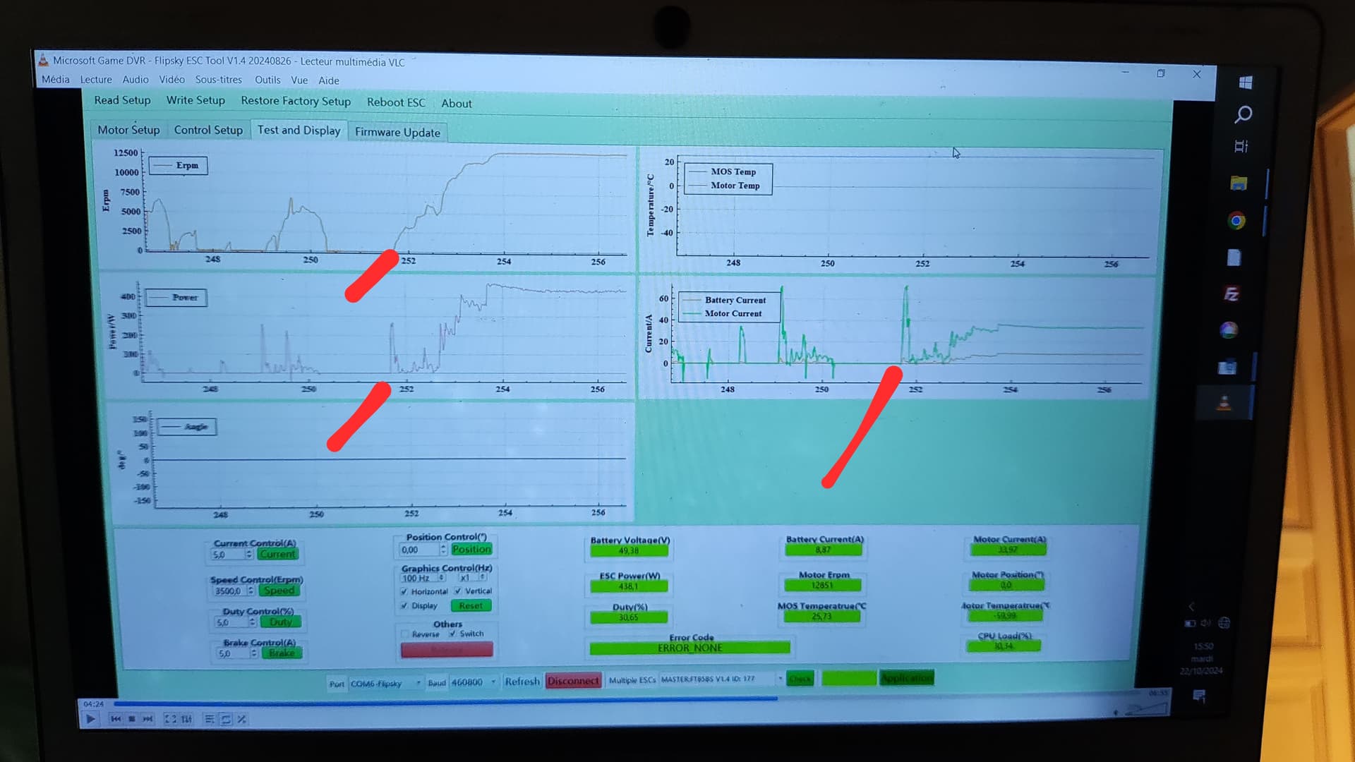
very interesting, I try to take off with my boogie (dual motor flipsky 6384 / NonVesc FT85BS / battery 13S6P 70A max) I record the log on one side only, after 251s, full power, motor rise to 60A. after 2s the rpm is max, but not enough power to lift my 70kg on a 1200cm2 surf foil. I would be curious to see other logs, the current peak does not seem normal to me, and I wonder how the rotation speed is obtained.
Several things, rpm for you with this motor is erpm/7 so rpm is only 1800 and the measured power is also only 400w. There’s the issue. Seems like the propellers are losing traction, flexing or sucking air - if there’s no rpm limit. Try the noload speed, do you reach full (kv x voltage) rpm?
thanks, why you divide erpm by 7 ?
I’ve just watch this video , 2 tests at 36V and 48V, not sur to understand the duty cycle, but that look I need a swimming for testing !
Erpm is electric rpms, and this motor has 12 slots and 14 poles. Each pole pair (1 north and 1 south facing magnet in the rotor) creates one electric cycle for the motor.
Therefore in one revolution the esc sees 7 electric revolutions.
In a formula:
Erpm=rpm x (no of pole pairs)
Rearranged for rpm:
Rpm=erpm / (no of pole pairs)
For those who would prefer to use ‘pre-loved’ battery cells, I’ve found salvaging from Dyson cordless vacuums are great as they also use high output cells. (35A in the ones I got).