It only creates heat based on how much current it uses. It should not get hot at all if it’s only connected to the receiver. There’s another issue somewhere. I’ve used BECs with no heatsinks and they’ve been perfectly fine.
3 Likes
No, should not create any notable heat
In this case the BEC seems to have ultimately malfunctioned, leading 50V directly to the Rx, killing it…
2 Likes
Ok, so guys, simply avoid this BEC ![]()
If it’s not BEC which create this oscillations, I would say it comes from 100deg temp protection.
It reduces power on motor always around after 15 minutes, I have to ease the throttle, push again and it restarts with a different noise.
But I know @Jesserosco system is the same and hasn’t got such issue. Moreover I’m in a colder area than him.
I’m going to hazard a guess that there was a voltage spike and that’s what killed the bec. In turn then it may have shorted out and damaged the receiver.
You also shouldn’t be hitting near 100° at the escs if you have adequate cooling. You definitely need to get the escs heatsinked adequately so that they sit at a maximum of around 50°
1 Like
something is wrong then, probably getting back fed somehow?
Maybe asking the obvious, but it says “up to 13S”
How many cells do you have in your pack?
I use 2x 6S10P in serie.
I’m planning on putting one of these in my next tow boogie: Go-FOC DV6s - MakerX
I talked to maker-x and according to them it should be able to handle 4000 watts burst and 2000 watts continuous at 42 volts. Wiring should be a lot simpler than using dual ESC and dual BECs. I will mount it on an aluminum plate with water flowing on the opposite side so cooling should be pretty good.
1 Like
@jenz that’s a brilliant idea ![]() Unfortunately too late for me!
Unfortunately too late for me!
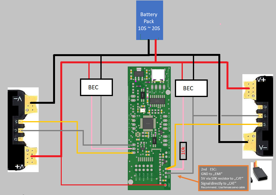
I’m planning the connections for my dual motor tow, i want to have clean connections (which i always find challenging). It easily turns into a rats nest… Basically, i think i need some advice.
Schematic:
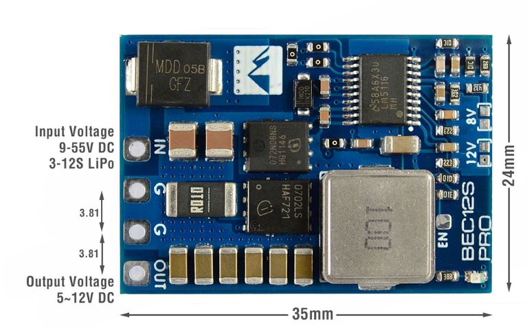
I got the mateksys pro bec which uses a pitch of 3.81mm:
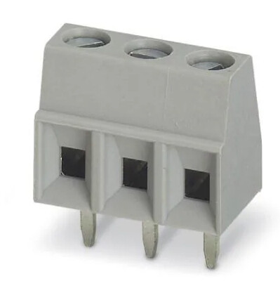
Was thinking about soldering a screw type terminal block on the BEC. Like this (but 4-pin):
Then for the connections to the esc and receiver use a couple of y servo cables, will need to be modifications to the wire on the second esc/non-standard connection side (with the 10k resistor).
What do you think, how would you connect the Rx/BEC/ESC? A custom pcb would be nice but i don’t know (yet) how to do it.
1 Like
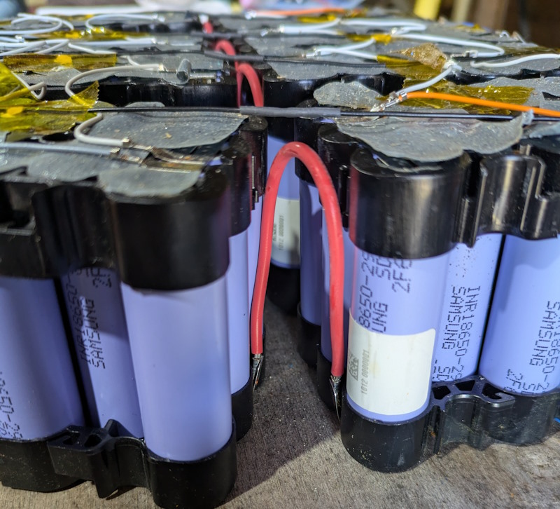
Newbie question here, I’m planning on repurposing a 10S11P battery for a dual motor boogie, 120A ESC on each motor. The cells are Samsung 29E which have a max discharge of 5.5A. Does this mean 5.5 x 11 that the battery will only be able to supply 60.5A max? Then 60.5A x 36V means I could get max power of ~2kw? If so, then I’d have no hope of being pulled up out of the water and I might be better to use that battery for something else which needs less peak power? I’d like to be able to use at least my 38L prone board on a smallish surf foil (Spitfire 900). I see Molicell P42A cells have a discharge of 45A, a massive difference!
Yes, the battery will be too weak. You’d better use it for something else since on the tow you are likely to 1) not get up 2) damage battery while trying
2 Likes
Can anyone point me to somewhere that has an electronic parts list with an explanation for each thing? I realize that might be a huge ask, but after reading a bunch of threads, all I have learned is that I don’t know enough about all these acronyms and parts to do this safely. Or at all. I have over a decade experience in making boards and there was a time when I knew nothing about that too so I’m willing to put in the work, to learn everything.
3 Likes
I’ve been reading this forum for over a year and only just starting on my build now (because I also have young kids so not much spare time), so that’s a great way to build a solid understanding before getting into it! I’ll try here for you as a basic starting point, and also writing this in hope that if I have something wrong, it will get corrected by others.
- It starts with working out how much power is required to give you enough pull to get out of the water, there are heaps of variables involved here, especially with single or dual motor, prop design and number of blades etc but from what I’ve read, about 4000W of power will be needed.
- The battery is usually made up of individual cells in a X series Y parallel config (XSYP). This is how you get the desired voltage you need. A single battery cell has a Max voltage (fully charged) and cut-off voltage (fully discharged) and a nominal voltage (the one printed on the packet). Voltage drops as batteries become discharged. Li-ion batteries ‘nominal’ voltage are ~3.6V each and Max voltage of 4.2V, so if you do a 10S (10 cells in series), that creates a ~36V battery. The charger for this 10S pack would supply 42V, because this is the voltage required to reach max voltage for the pack. Most Boogie builds on here are 12-14S, so voltages 43-50V.
The number of Cells in Parallel contribute to the total current you can draw from the battery, effectively ‘sharing the load’ of the power delivery over more cells means less stress on each cell. In addition to this, the sum of each cell capacity makes up the total battery pack capacity. More cells = more foiling time per charge. The cell itself has a max discharge current, and it’s important to use high discharge cells, because for a boogie to pull you up out of the water, it’s needs a 5-10 second burst of really high power. On a basic level, to get 4000W at 36V, you will need ~111A. I had a 10S11P commercial battery pack (Stihl AR3000) that I was going to use but after seeing the cells inside were Samsung 29E, they only have 5A discharge, so 5A x 11 cells is only 55A. Compare the Cell output of the Molicel P45A which has a discharge rating of 45A, a massive difference in power delivery. You also want to overspec the battery pack so pulling less current than it is capable of delivering in order to not heat it up too much (Heat kills batteries). - BMS is Battery Management System, because battery cells are ‘dumb’, they don’t have any function to know when they’re too high or too low, usually the BMS controls the charge and discharge of the cells in order to prevent over charge or discharge, BUT because of really high discharge required for boogie, BMS is often only used to charge, and the ESC is relied on to stop batteries from getting too low. BMS usually also come with a balancing function which have a connection in between each cell set connected in series to check expected voltage against actual voltage and supply charge current in a way that evens up the cells.
- The battery then supplies power to the ESC (Electronic Speed Controller). This is the ‘brains’ of the operations, because it also takes on the instructions from the remote receiver (Rx), and sends the power to the motors. It is usually configurable so you can set plenty of variables such as ramp-up power, temperate controls, and cut-off voltage etc. Note here, remote = Tx (Transmitter).
ESC’s can get hot, so need to be cooled, and because we operate these tings in water, it’s not so simple to keep them cool. - Cables, AWG is often used to refer cable thickness so you can look that up separately. More current needs thicker cables. If you use too thin a cable, they will heat up, wasting energy, and in extreme cases melting the casing even melting solder which is very dangerous due to the risk of a short (circuit). In general, the highest flow of current will be between battery and ESC, and it seems 8-10 AWG is common on the Boogies here. The connection plug need to also handle the current, that’s where your XT90 or QS8 comes into play (edit: good idea to use the anti-spark versions of these connectors). Sometimes because the BMS is used for charge only, you’ll also do an XT60 connection for charge only, as charge currents should be kept lower to avoid heat issues, just a few amps for charging.
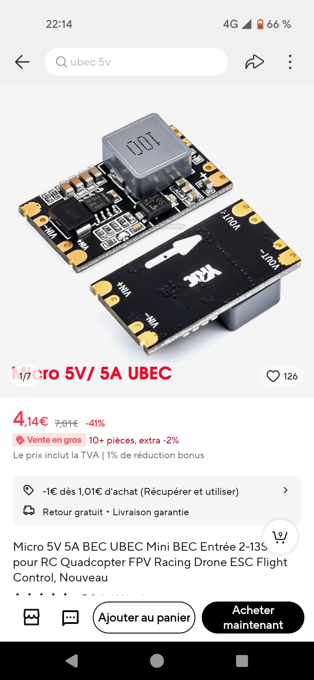
- The Receiver board needs a much lower voltage to operate (Usually 5V), so the most common way to supply power to the Rx is to use another chip called a battery eliminator circuit (BEC) which has the sole job of reducing voltage to supply the Rx. Some ESC also have a built-in BEC, but not the ones commonly used with Tow Boogies.
- Then there is kv (Constant Velocity) ratings on the motors. These are Brushless DC motors (BLDC). This is how fast the motor will spin with no load on it, or the RPM when 1V is supplied. At this point my understanding gets blurry so I just use whatever others have had success with!
The first 3 mins of this video summarise the system well. https://www.youtube.com/watch?v=yiD5nCfmbV0
11 Likes
Pretty good overview I think @seagull_nz
One item you didn’t mention is some sort of anti-spark measure. When you take connect a battery of high enough voltage directly to a circuit you may get a large snapping spark as you make the connection. In this case of connecting to an esc I believe the capacitors (which are “empty”) will briefly draw a very high current and this why there’s a spark (someone please correct me if I’m wrong here). This can be harmful to the esc if you do it repeatedly, and it’s also just kind of annoying and a bit unsophisticated.
The easiest way to avoid it is to use anti-spark connectors (like QS8 or and xt90 with anti-spark). There are also anti spark switches (though these appear to have questionable reliability). You can also set up a pre-charge circuit
3 Likes
No, motor current is higher than battery current so you often use larger connectors and wires on the motor side.
3 Likes
Super helpful. Thanks so much. This both makes me realize I need to be more patient but also helps me know what some of the terms mean.
1 Like
Hey, on the question of the spark, anything you connect to the battery will see that spark if the circuit/object is at a significantly lower voltage (potential) than the battery. IE the ESC, a stray screw driver, or a battery charger that’s turned off will spark if you connect them to the battery. The last one is applicable because if you’re not using a BMS, you can avoid that mismatch in voltage between the battery pack and the battery charger by turning ON your battery charger to roughly the voltage of your pack.
The circuit is typically done as recommended with a bleed resistor in the connector which allows a small amount of current to flow, bringing up the voltage to the same potential to the battery pack and thus avoiding the spark.
2 Likes
Not an expert, so happy to be corrected, but for practical purposes you want to have larger gauge cable and connectors on the battery compared to the motor.
The motor shares the current over three phases so is less by a factor of approx 0.58. Ie if the total motor current is 100A the total per phase would be 58A.
The other reason is that the motor cables are just a continuation of the windings. Lower gauge will have little effect to the over all system.
The battery cables on the other hand have to handle any back EMF from the speed controller and you want them as short and as thick as possible to prevent damage to the vesc.
4 Likes
Thanks, good point re windings. Dual ESC/motor boogies will also draw 2x current from the battery to the splitter supplying each ESC? My splitter is QS8 to double XT90.
Those are good points but i don’t think they’re necessarily relevant for the total losses in our use case as:
- motor cable length can be 120cm and battery wires 30cm or less. That’s 4x difference.
- motor wires receive the motor current which can be several times higher than battery current, as the peak power used is normally at starts if you are foiling. (If you’re maxing your system at high speed then difference between battery current and motor current tapers off.)
For the tow and foiler combination i’d guess the power need depends on how aggressively you ride? Would be interesting to see some logs, i guess the most agressive carving is done with high load and lower rpm at the prop (=large motor/battery current difference)