Thank you Peter for your kind words. Just want to add, there will be an IMU on the receiver side as well, doing exactly what you planed. This will give a kind of redundant system. If the remote side fails to register a fall, hopefully the receiver side will. The IMU on the receiver side will also make sure that the board is in level before you can start riding, reducing the risk for starting the motor by accident
Great! I read over your initial post and it looks like you had a motor cut planned with IMU data. I would be careful writing code as simple as if (I > threshold || J > threshold || K > threshold). I don’t think we need to train a neural network if we want to be simple but we cannot be so naive as to assume that our riders bail parallel to the X, Y or Z axis! I myself when traveling along j-hat bail with an acceleration vector of -0.5j+2i! Only kidding, I don’t have the data to make that kind of insight about myself yet. My joke was meant to ensure the a threshold is found empirically for the magnitude of the acceleration vector rather than it’s components. I don’t want anyone to get hurt because of an easy to make vector math mistake.
 I have no plans of training a neural network, don’t think the teensy is up to that. I think it will be enough to calculate the linear acceleration from the quaternion on all axis and if the average acceleration of all axis or one axis exeeds a given threshold, we have man over board
void MPU9150::GetLinearAccel(const float* quat, const float* accel, float* linearAccel)
{
    float gravity[3];
    GetGravity(quat, gravity);

    linearAccel[VEC_X] = accel[VEC_X] - gravity[VEC_X];
    linearAccel[VEC_Y] = accel[VEC_Y] - gravity[VEC_Y];
    linearAccel[VEC_Z] = accel[VEC_Z] - gravity[VEC_Z];
}

void MPU9150::GetGravity(const float* quat, float* gravity)
{
    gravity[VEC_X] = 2.f * (quat[QUAT_X] * quat[QUAT_Z] - quat[QUAT_W] * quat[QUAT_Y]);
    gravity[VEC_Y] = 2.f * (quat[QUAT_W] * quat[QUAT_X] + quat[QUAT_Y] * quat[QUAT_Z]);
    gravity[VEC_Z] = quat[QUAT_W] * quat[QUAT_W] - quat[QUAT_X] * quat[QUAT_X] - quat[QUAT_Y] * quat[QUAT_Y] + quat[QUAT_Z] * quat[QUAT_Z];
}Yes the Teensy cannot train a neural network but I was shocked when I learned how simple of hardware can run a neural network. I am student in the Machine Learning class at SCU right now. Once you train a network you have a couple of lists of numbers (weights and biases but names are not important) and these numbers can be thought of as scalars in a big huge long math expression. The training you’re thinking of does like you said require hardware up to the task of matrix multiplication and other stuff. All said, a neural network is overkill if we can get good results with this approach.
I have no real issue with using Y=(X+Y+Z)/3 for setting thresholds because it at least incorporates all terms of Y=X^2+Y^2+Z^2 (formula for magnitude). If you go with the averaging approach please take the absolute values before averaging in case I decide I’d like to be able to bail off both the back and front of the board. The magnitude uses squares to account for negatives.
Best,
Peter
Peter, it really looks like you are into this. Yes, I have already used the absolute values before averaging but I have no problem going for magnitude instead, if you think that is better.
1 Like
Look in the datasheet of the chip most of the modern IMU’s have free fall detections feature built in. But still personally I wouldunt relly on some 50 to couple of hundred hertz latency plus some other latency in transmission and firmware. Yes it will work but in some extreme cases might not work. Like that pro french guy who managed to put his finger in the prop faster than the failsafe.
Implemented in the iUP hydrofoil from Taaroa to be released soon see:
Before talking about AI algorithm we must first identify the sensors and actuators of the agent. In this case an IMU as the sensor and a moving flap as the actuator. I have yet to see this style of actuation in an e-foil system and am deeply skeptical over its robustness. Until the actuation mechanism is proven I will not comment on the AI control algorithm.
So it scores a 1 out of 2? Not quite. In order for an IMU to be able to detect foiling height one must ask what is height? It can be thought of as a difference in the Z component of two position vectors. Ah, position! But my IMU does not give me any positions it gives an acceleration vector? Right, recall introductory physics/calculus: derive position to get velocity, derive velocity to get acceleration? A relationship between my sensor values and desired values, woo-hoo! Not quite. What happens when you derive a constant? You get 0. Inversely, what happens when you integrate? You end with a + C which represents some constant that was derived (to 0) from the input expression to the integration. Spell it out for me. If you integrate acceleration you get velocity + C and for our sake C is really hard to find. To make matters worse, you must integrate this to get position.
To put an end to this, to determine foiling height from an IMU one must be able to successfully integrate the acceleration vector twice. You will find some cutting edge research papers working on techniques to estimate lost constants but the technology is not robust. If it were, cell phone owners would probably be more sensitive over their IMU data like they are with GPS.
0/2
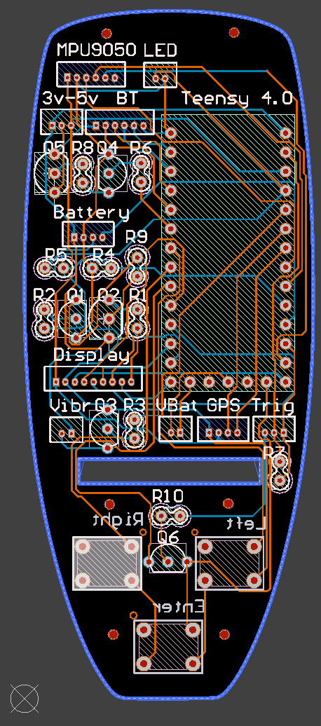
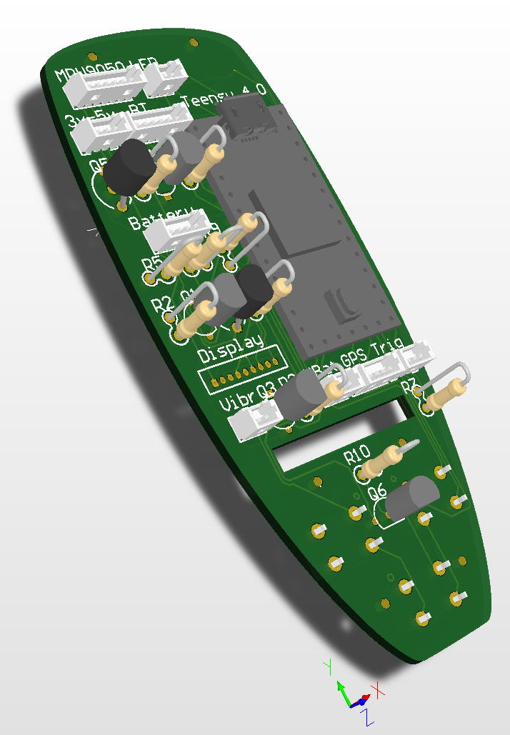
The final PCB (hopefully) is now uploaded to Seeed Fusion. I addition to the forgotten resistors, breaking out the IMU and adding connectors for the backlight, there where a few other problems I had to address. The tactile switches I used in the drawing program was using the wrong pins to close the circuit and in order to get the on/off functionality to work correctly, another transistor and resistor was needed. I will update Post 38 with the new Gerber files, schematics and parts list.
New PLA is on it’s way and I will start printing the “production” remote as soon as the filament arrives.
If anyone is interested I will try to do a step by step tutorial of the entire process of assembling the remote.
11 Likes
hello YAHEF
would be great your tutorial proposal, thanks
I can’t wait for the final version… I really would appreciate a really detailed instruction over the remote assembly.
I have ordered most of the parts… just a few minor things as the greber files and order a circuitboard.
But I’m waiting for your final version.
Br
Magnus
Göteborg
What a coincidence. Just 10 minutes ago, DHL knocked on my door with the new PCB. Will try to solder one tonight and let you of the result.
My deliveries has snail mail start to look like rocket delivery.
Ill guess it will turn up some day. No rush right now.
Disaster!!!
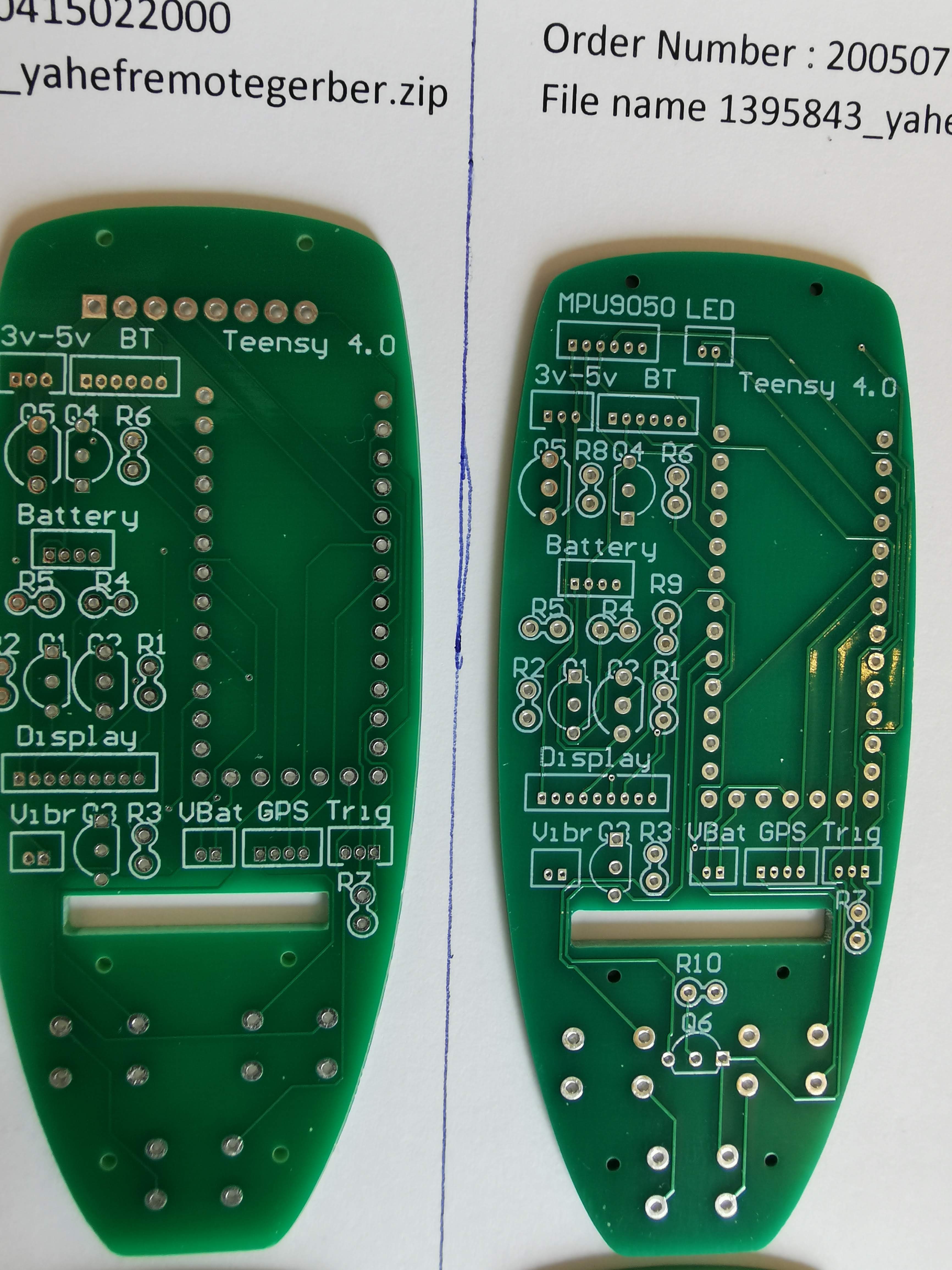
There was a production error on the new boards. All the holes are too small. Can’t get any components through the holes except the transistors and resistors. If you look at the BT connector you can clearly see the difference between the old and new PCB. I have compared the drill files and they are using the diameter.
Can you not just redrill?
How many layers is this PCB?
It’s just a 2-layer board so yes, I thought of that but I don’t have a 0.5 mm drill bit. Can’t find one at my local hardware store either. Will probably need to order 50 of them online since I’ll most likely will break one for each hole
Hopefully Seeed will answer me on Monday and start a new production. That will set me back one week with the remote, but I have plenty of other things to do instead with the board so I’ll concentrate on that
1 Like
That’s good news that it’s 2 layer. I’ll be able to mill out a PCB then!
I want to design a more modular based housing that can be pour moulded and uses a 18650 in the handle. With an easy waterproof screw cap to pop the battery in and out for charging…
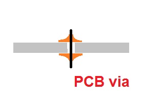
I should be doable to mill the PCB, just look out for the via holes. Also. a lot of the ‘regular’ holes are also used as via. Could be a bit tricky to get the solder to flow to the other side of the board
Interesting, please tell me if you want to alter the layout or size of the PCB. I’ll be glad to help
What about using a thin metal link, pin or strap ?
It looks like the second layer is only via holes?
If that’s the case I’ll just mirror the cut so it’s on the bottom.