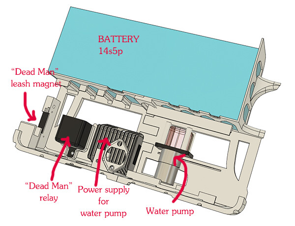
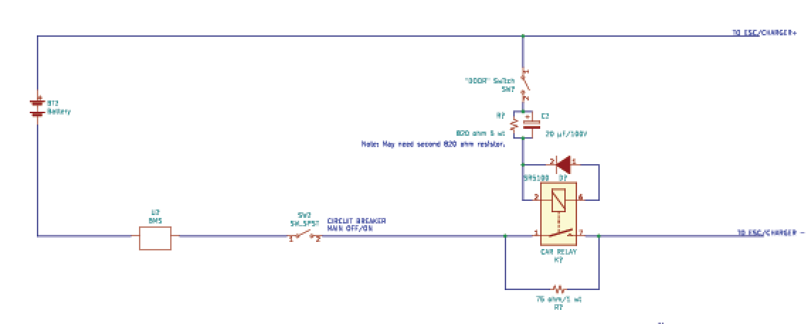
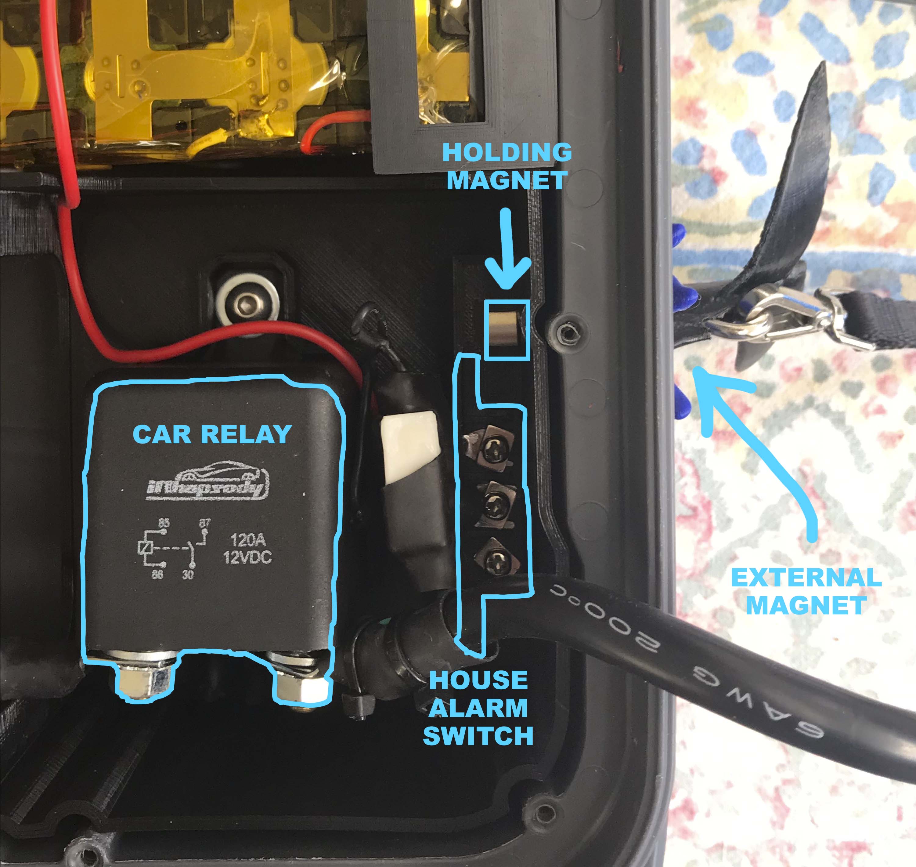
The car relay is closed when the “door” (or “house alarm”) switch is ON.
The “house alarm” switch (the kind of rectangular switch you find on doors or windows that must be closed for the house alarm to be on) is in turn activated when the external magnet (attached to the safety leash) comes close to it.
In order to maintain the external magnet in place, there is a “holding magnet” inside the suitcase. You have to be careful that the “holding magnet” doesn’t trigger the “house alarm” switch though.
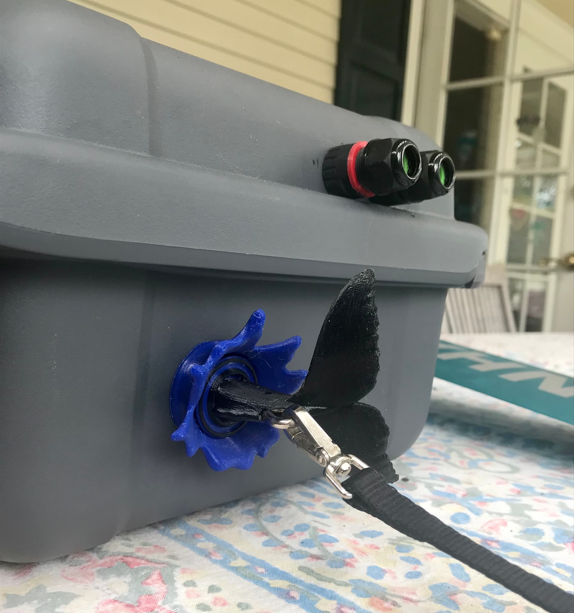
Since there is no reason not to make it pretty, here is what my safety leash looks like: The external magnet is in the fish tail. The blue splash is glued on the suitcase, so that the external magnet doesn’t slip around.
THE REMOTE CONTROLLER
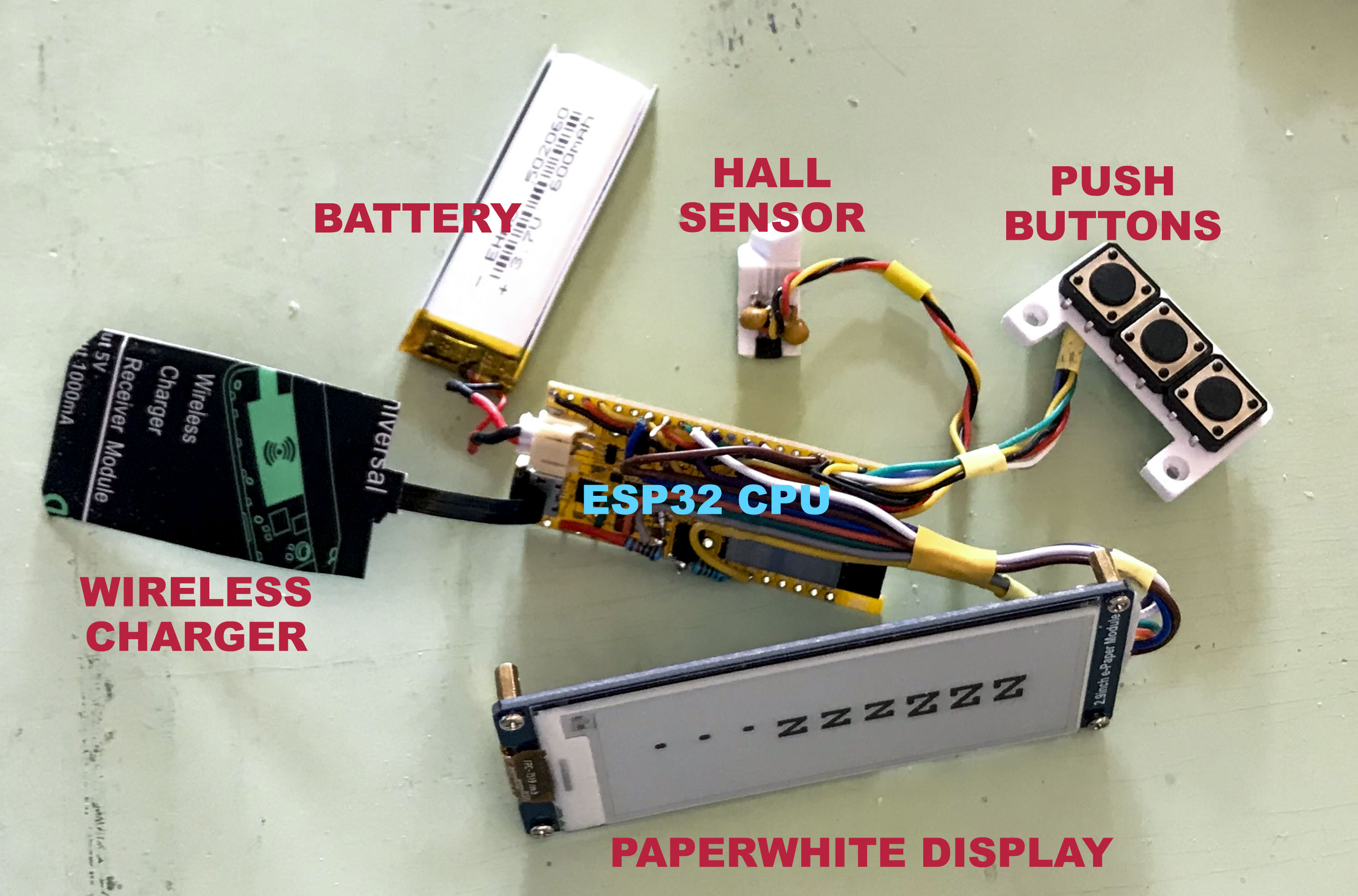
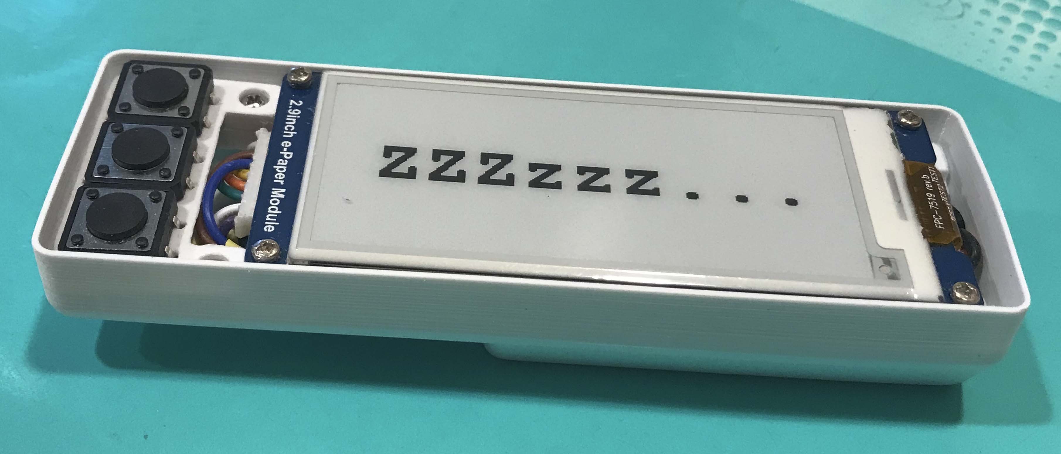
We started with a cheap off-the-shelf remote, and then we decided that the only way to know what’s going on while we’re riding is to build our own. So here we have:
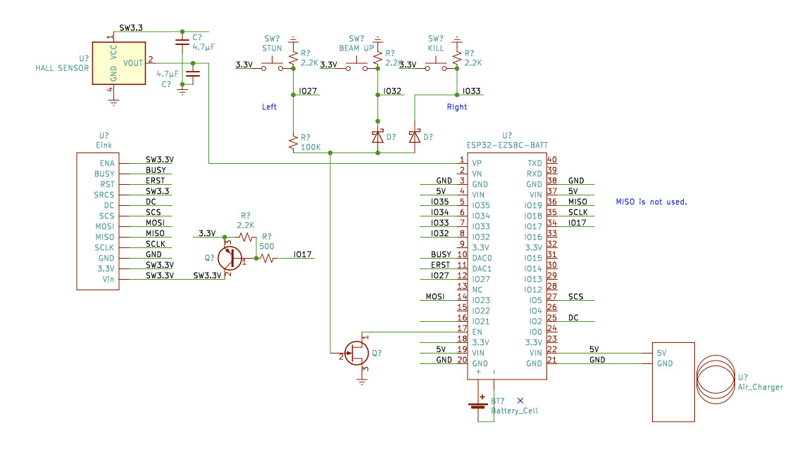
Control board: ESP32 CPU
Battery: 600 mAh 3.7V cell
Wireless charging: 6$ coil and card
Pushbuttons: labelled STUN, BEAM-UP and KILL, but not necessarily for that usage
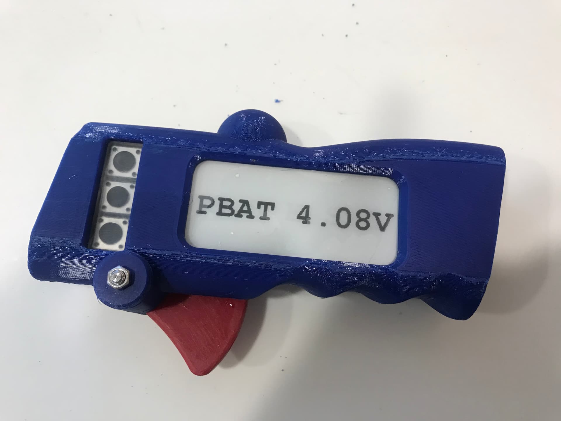
Hall sensor to read the position of the trigger
Trigger with magnet to be detected by aforementioned Hall sensor
and, most important, a large “paperwhite” display that hopefully will be readable in the sun
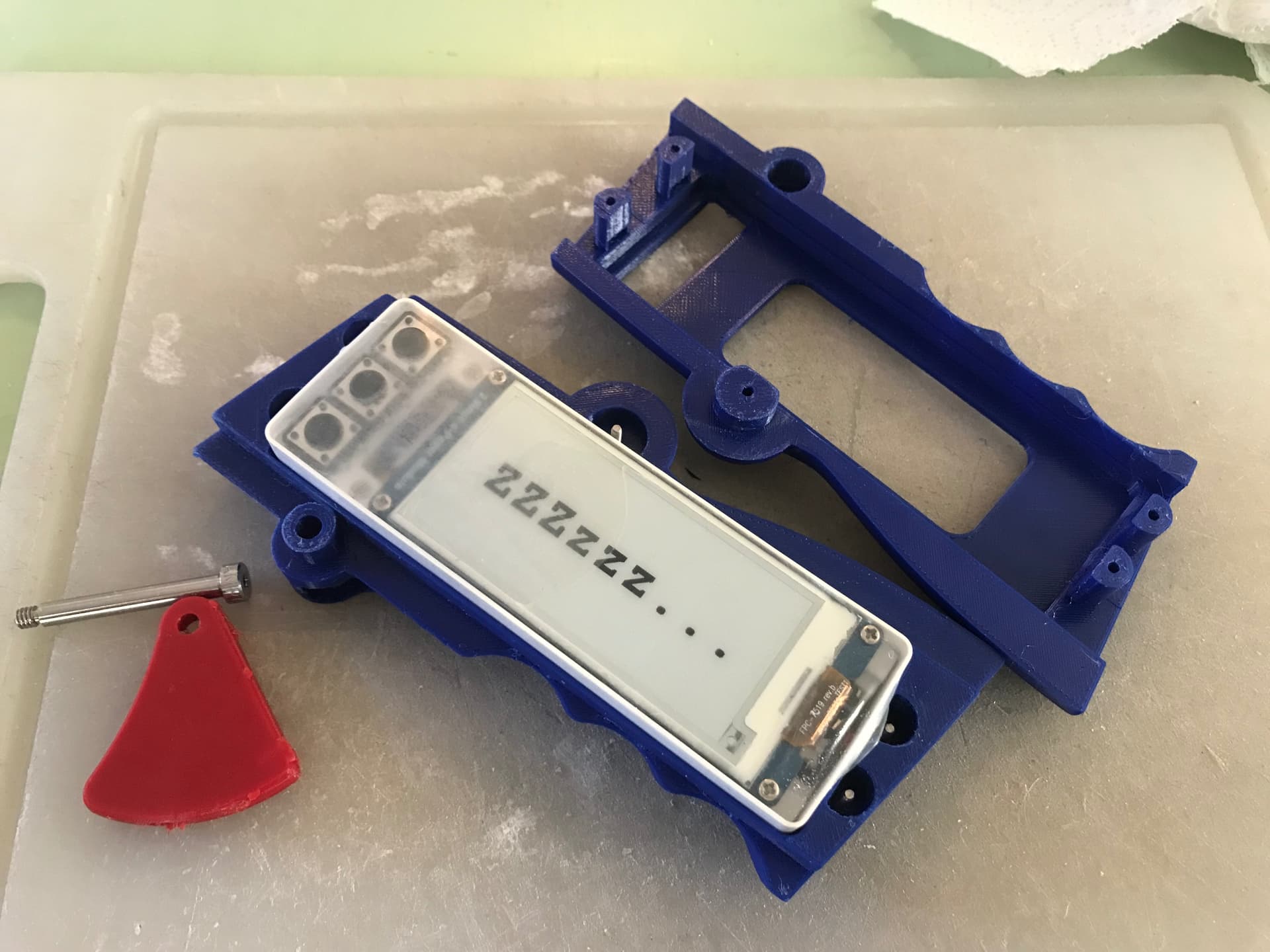
All these components are cheap, but, as we learned, they tend to be fragile. In particular the card for wireless charging, and the display connectors. We killed quite a few while debugging the system.
… which is waterproofed using the universally approved method. (The nice feature is that the display is still very readable through the liquid proof barrier.
We’ll keep the community posted and share the design when it’s finished. Be aware though that building the ESC hardware is quite tricky. Debugging the ESC software is a lot of work, but at least, we are confident that it will eventually work.
Right now, it’s built like a fortress… (the first version we tested burned due to insufficient waterproofing!)
So, waterproofing is easy, just pot the whole thing in epoxy. If your fets are next to aluminium and you can get the heat out of them, it should work. However, (when we have tried to do this with off the shelf ESCs) we have found that there will be some components in the electronics that will heat up and die.
There is a real market for a robust marine ESC that is capable of 9 - 15kW. You could have an air-cooled version with a big heatsink, or which is always exposed to water or you could throw a water cooling block on it.
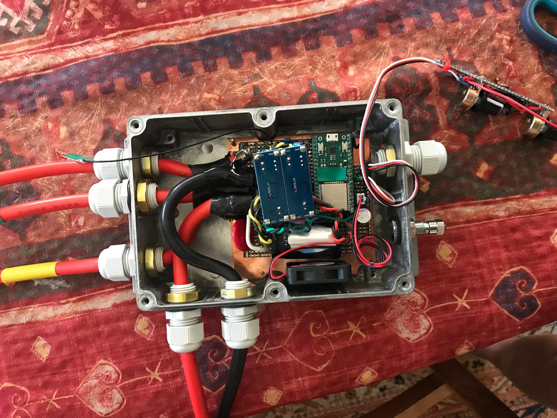
We have the issue that our battery is LiFe and we are pulling 90 amps out of it and it is surrounded by foam, so we have built an aluminium box for it that is water cooled.
“there will be some components in the electronics that will heat up and die”…
That’s why waterproofing gets complicated…
As far as cooling is concerned, for now, the FETs are attached to a copper plate which is attached to the metal box, which is located under the board (so in the water when starting out, then in the air). ESC temperature is displayed in the remote control screen. So far so good, keep our fingers crossed.
We haven’t been able to ride long enough to see if we have cooling problems for the battery!
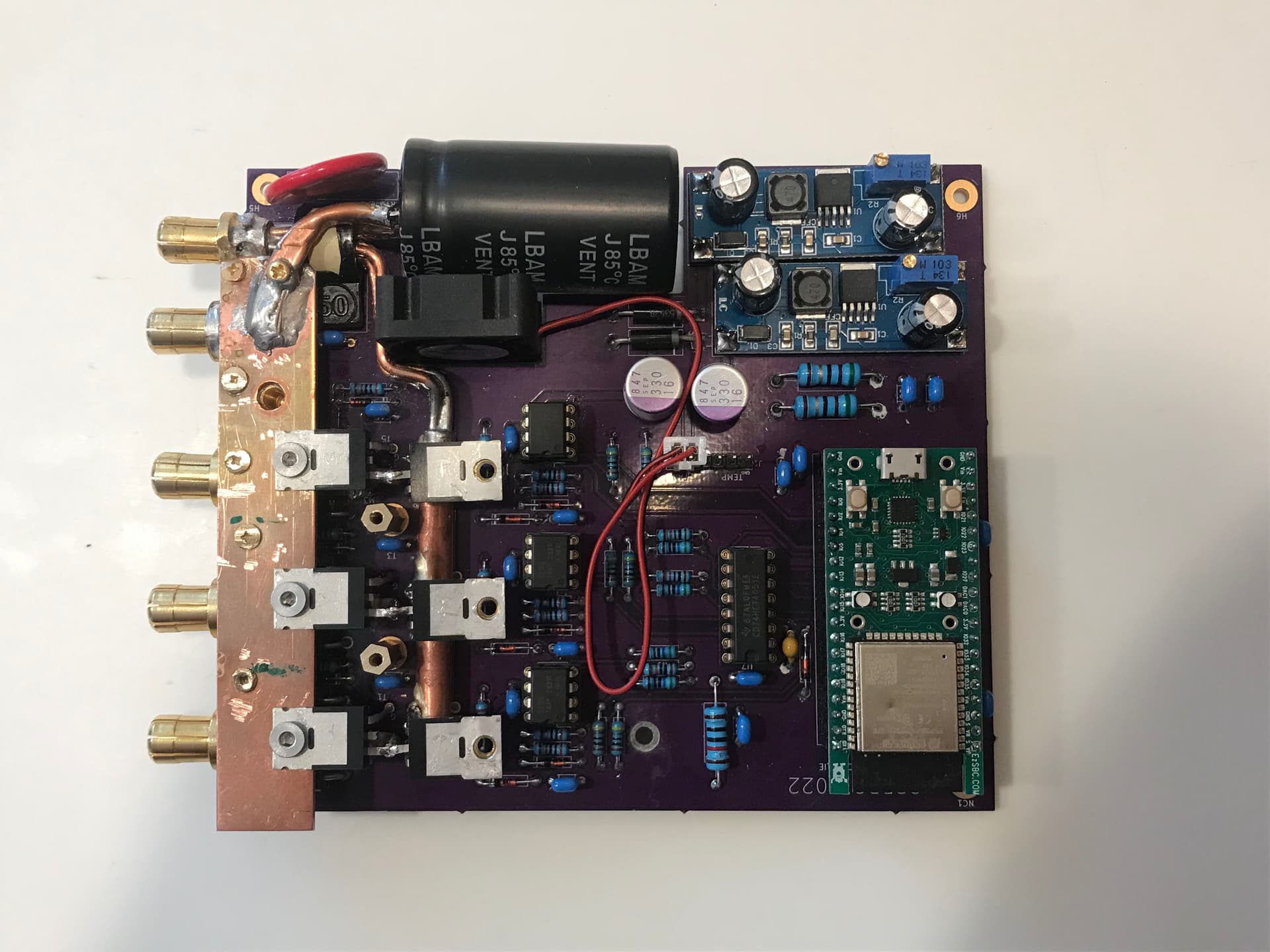
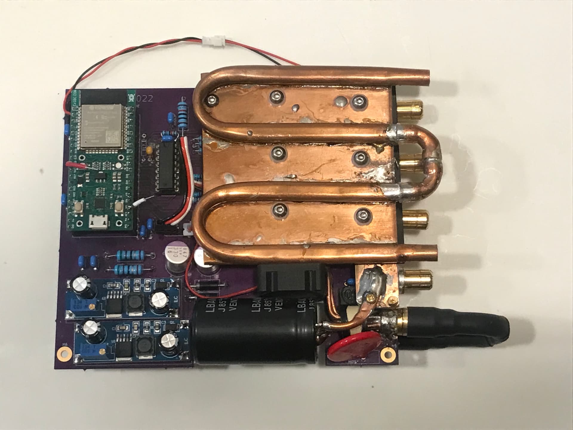
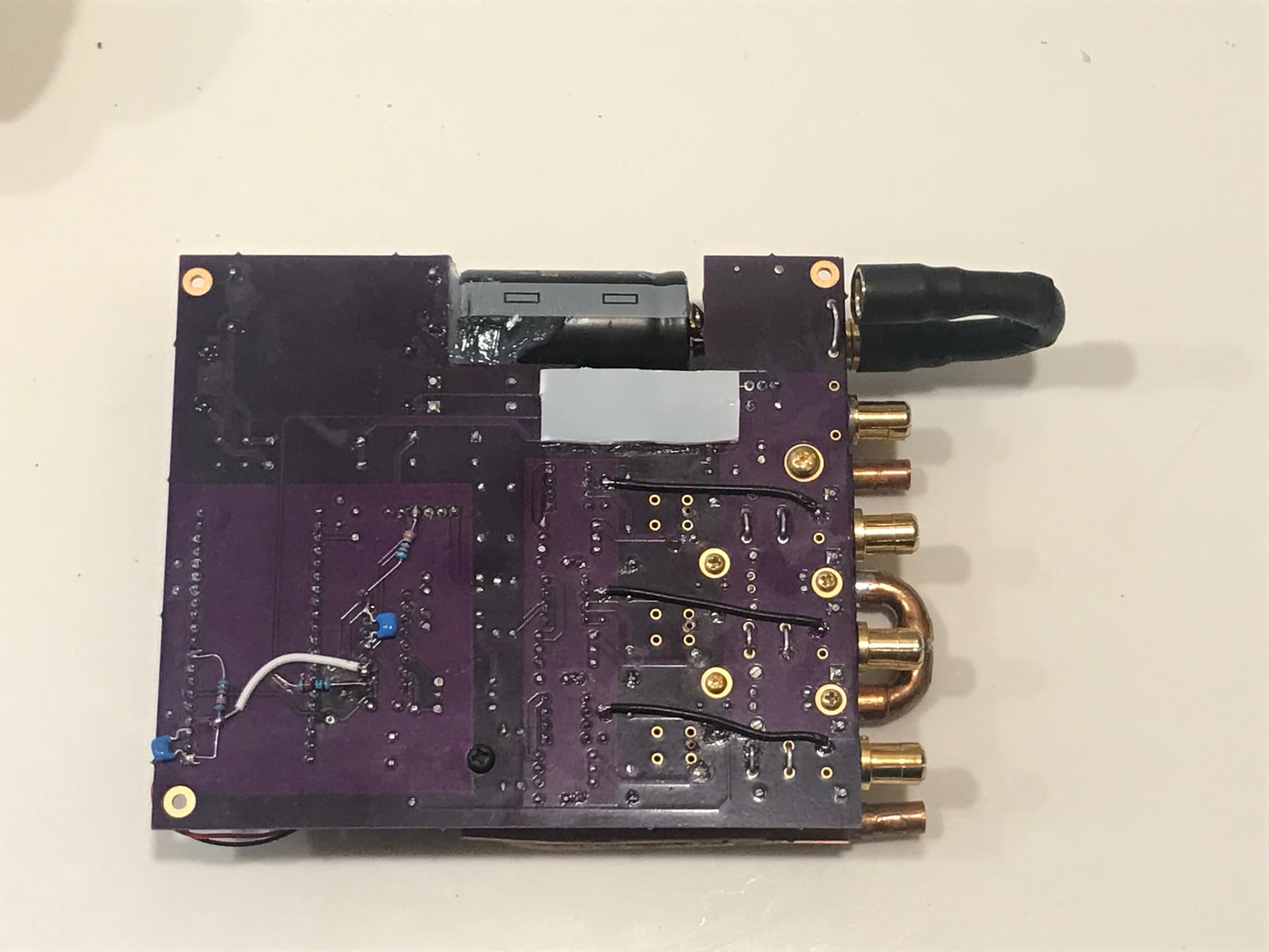
Charlie has now made a PC board for the ESC, which now looks like this (We haven’t gone out on the foil yet, but at least we have a beautiful homemade ESC) :
BUILD #2 - Water-cooled ESC
We are “back in business” after a long absence, however things are moving very slowly due to severe conflicts of interest, since the kiting season has started again here. Fortunately, Charlie is not a kiter, so he has finished this new-water-cooled-homemade-from-scratch ESC, which is now complete (or so we think…).
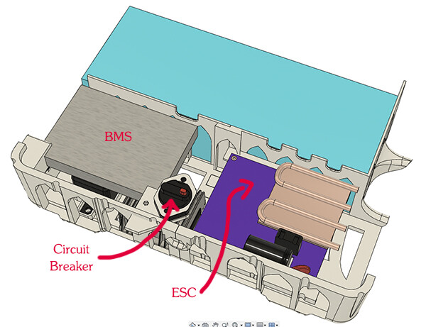
The ESC now lives in the same case as the battery. We should have done that from the start, but we thought that having the ESC under the board would simplify matters. This was definitely not the case: waterproofing proved to be tricky, leading to a heavy unappealing not-easily-portable ESC unit.
So we are starting on Build #2, even though build #1 hasn’t flown yet…
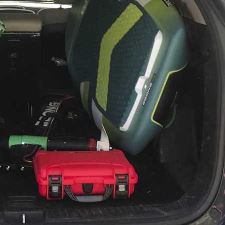
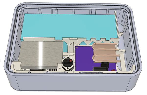
We had to build a new suitcase, using the larger Nanuk 920, because the Nanuk 915 we had before didn’t have room to comfortably add the ESC, pump and pump power supply. So that’s the new design: .
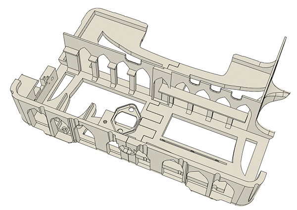
Using the templates for the internal volume of the suitcase provided by Nanuk, I designed and printed this gothic-looking insert to hold all the components in place. It took almost 40 hours for my Prusa MK3 to print it!
(Retrospectively, it might have fitted in the Nanuk 915.)
Photo of the real thing coming-up…
First, we added Water detection to the bottom of the suitcase. The presence of water is detected by the change in resistance between the 2 metal strips, connected as inputs to the ESP32 processor in the ESC.
And, with the help of some CAD, 3D printer and a good shoe horn…
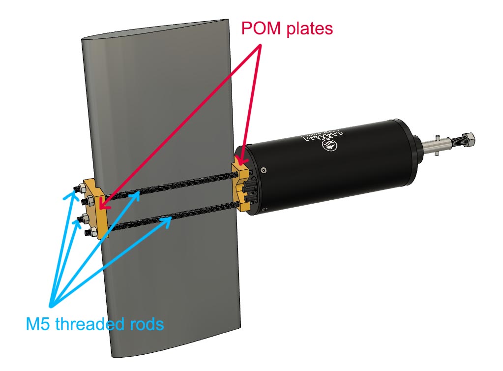
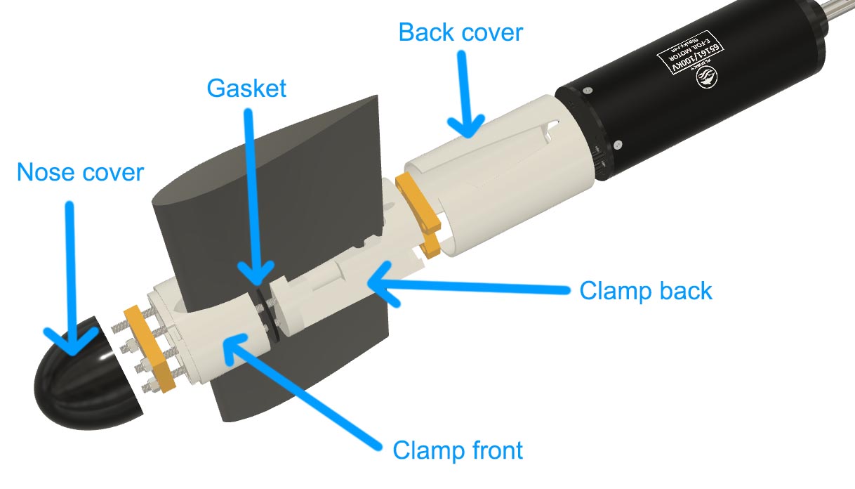
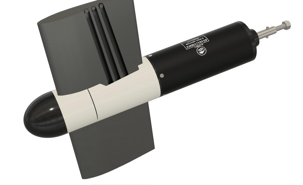
Updated Motor-Mast Clamp
I reworked the clamp to make it sturdier. Looks like I “re-invented” what several people on this forum have done a long time ago.
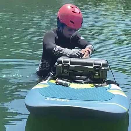
Day 1
Now, it’s very obvious, I need to learn how to ride the thing… This is my first time ever riding an eFoil. Kitefoiling doesn’t help much, other than knowing that what seems totally impossible at first might in fact be possible.
It looks like there is plenty of power. Maximum Amps (before crashing) was 45A for 50V roughly. And I could have taken off with less. Our ESC works very smoothly. The remote controller needs a little tweaking. The 105 liter GONG board is perfect for my weight. It’s about to sink but still floats. For now, we are using the big Yamaha-type propeller that came with the motor.
I realize that I need to go further forward on the board. The battery case is pushing the tail down. Is that even going to work? How many hours of practice will it take?
Please, I need advice! What would be the best placement for the battery/electronics case (25 lb) ? I thought it shouldn’t matter too much given the I am already 145 lb with wet wetsuit and everything, but I could use some insight here.
What wing are you using? Might have too much lift for you or AoA is too big. Some shimming might help. Your position seems to be quite far in front on that picture. On most efoil setups you have the back foot slightly in front of the mast and the front foot around 60cm apart. Try to push the board down while accelerating. Don’t release the throttle when the front of the board lifts too high, push it down. Bendig your body forward and lean on the board nose could also help to keep the nose down when launching. I don’t think it’s the weight of the battery box that causes the board to stall. Best placement is where it is not in the way.
It’s a Gong WingFoil wing, about 1900 cm2. So definitely very big! First thing, I will put the mast further back: I have an extra 1.5 inch on the track. I also need to install some foam traction pad at the front of the board so my front foot can move a little bit more forward if needed.


 .
.