First I want to congratulate Ludwig for this incredible piece of hardware and software? This is truly impressive and the way he gives answers is also impressive.
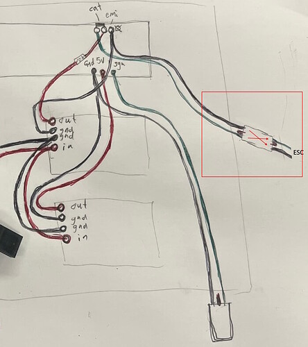
I ordered the electronic Bremote, oprint with my 3D printer the plastic, built it and did all the stuff with the software. It works great on one motor but I want to build a tow with 2 motors. I have 2 flycolor 160 and 2 BEC? When I watch the schema, I do not understand anything because from the flycolor I have just a GND and a PWM (yellow cable). The 5v come from the Bec. So I miss a lot of wire!!!
Which BEC do you have? Something happened to my last reply, so I have to add this for it to post for some reason.
There is good wiring diagram for dual motor here Larsb tow build, Bremote LR and dual motor steering Credit also to @Jesserosco for Pioneering this differential steering.
I have a Mateksys MicroBEC 12S.
I will check that. this forum is so rich that i miss some parts
I would highly encourage you to spend the money on the mateksys pro BEC. I had many issues with the smaller one and I think others on here have also. Since I changed all 3 of my boogies to the pro version I never have any weird anomolies. I also keep the BREmote RX board unplugged until after I connect the battery in case of a voltage spike to the RX board.
https://www.getfpv.com/mateksys-12s-pro-bec-9-55v-to-5v-8v-12v-5a.html
Basically you run the power into the BEC from the main power pad on the speed controller, one ground to the main negative pad on the speed controller, the second ground from the BEC goes to the small ground pad by the signal pad in the speed controller and the power out from the BEC up to the RX board. So the only thing going directly from the BEC to the RX board is the 5v power. The signal and ground come directly from the speed controller. Hopefully that makes sense and there is a few diagrams floating around, I know I posted on jdubs dual motor boogie topic if you search.
I have ordered 2 BEC Pro . Not very expensive
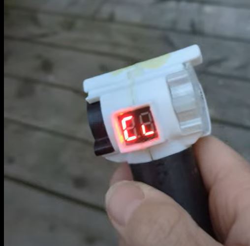
My display is slowly dying. Some of the cells on the display are weak or inactive.
It started after a poured a second ‘top-up’ foam, so can I just assume it’s due to poor connections that were maybe disturbed by the foam? The only way to fix is to open the Bremote and improve the display connection?
Could the foam have pushed the display out a bit? Can you try pushing on the display to see if it gets better?
Yea I’ll try that, I also used 5 min epoxy around the display frame so will have to cut that first.
Hey BREmote crew!.. has anyone down here in NZ (or maybe AUS) managed to source a suitable magnet for the throttle and toggle? The N52 spec of the original doesn’t seem to exist on this side of the planet and the linked sources above don’t seem to ship to NZ… I tried a slightly smaller magnet (closest I could get in NZ) and it is not grunty enough to give a reliable signal…
Hi,
Just a question.
My Bremote shows the value of the foil battery and 0c.
What does it means?
I have no VESC just a normal ESC connected by PWM output of the receiver.
Many thanks
Stefan
0c = 0°C ESC temperature
This feature only works with VESC
Solution: Disable #define SHOW_TEMP in the Tx config
All those settings are explained here
Very cool that you added the reverse functionality. Now I will give it a try. The new design looks also very promissing.Does it float by itself because it is so skinny? Thank you for sharing your skills with all of us.
People say that the PU foam is hard to get.
I found the Talamex PU foam on the Waveinn webpage.
It was about 20€ and was shipped quite fast to Germany.
BTW: I have a lot of leftover. If You need some foam near Bremen, contact me.
I need one (or a few) bremote LR-receiver for my next tow project.
Is anybody in Europe/Austria who has one left and wants to sell it to me?
Or is there a “simple”/preconfigured way to buy at JLC?
Thanks!
I got a complete LR Kit
@Jesserosco Another question I’ve only thought of now about remote calibration with BLHeli32 on dual motor boogies as I still can’t get it perfect. Do you calibrate each ESC separately or at the same time?
So I was careless when playing around with my dual motor tow boogie and plugged the ESC gnd/signal cable in reverse, now I’m not getting signal to the ESC on the ‘10k’ side (after connecting it the right way). I haven’t checked for bad connections but in theory have I messed up here? What steps should I try to troubleshoot?
The BEC is still working outputting 5v?


