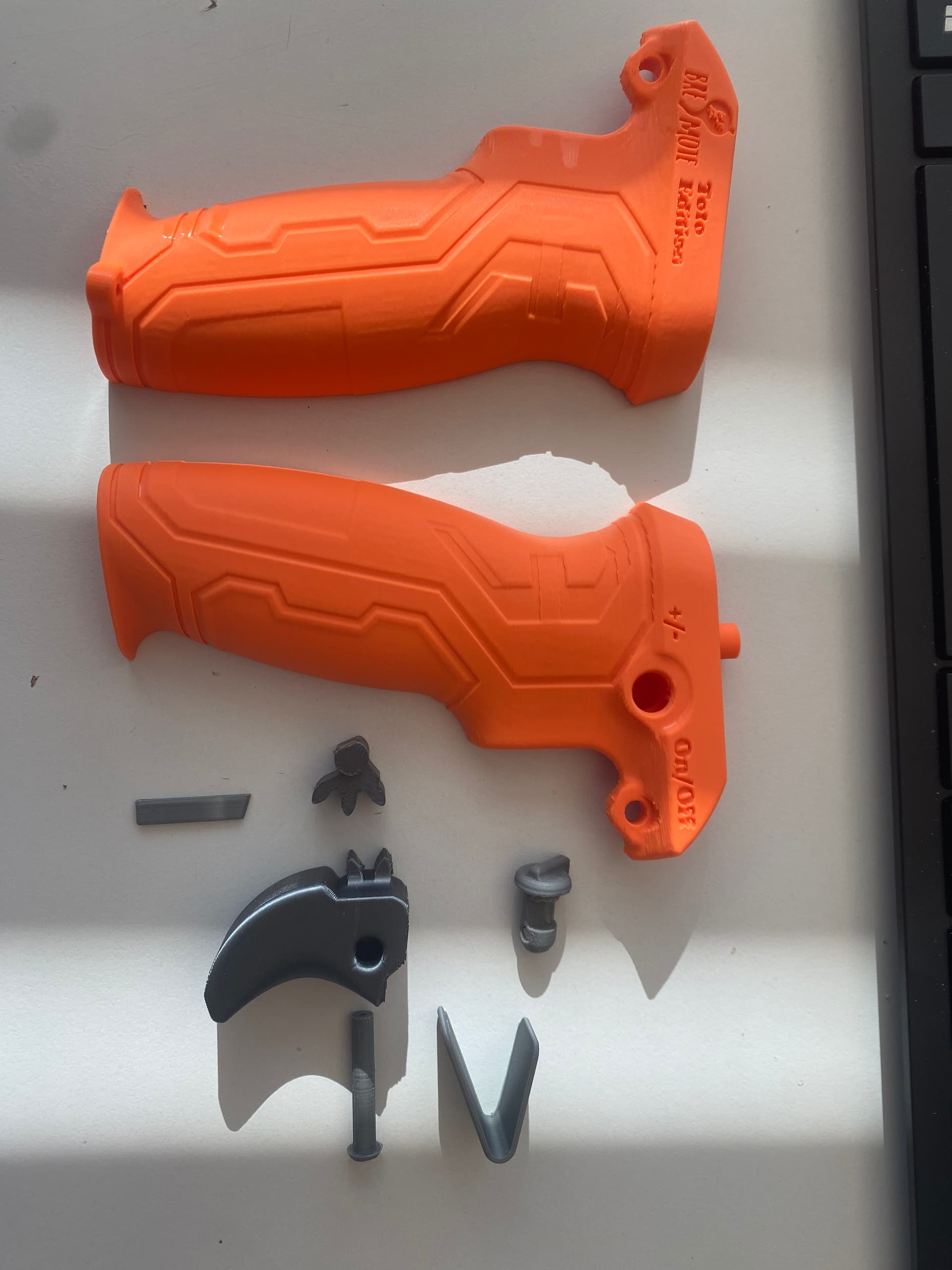
Cool design. How does the trigger mechanism work? Is the trigger-feel or tension adjustable? I assume the “V-shaped” part is some kind of a spring?
I tested some different “springs”. This one is comfortable.
‘Printed in ABS’ is not the most common material to print, so spring properties could vary too much when printed in PLA+, PA or PETG. Maybe some trail and error is needed here when building this housing and adjust for material and personal feel/experience. Should be no problem.
Do you have a picture of the trigger/spring mechanism? There is some kind of switch/lock on the side of the remote housing as well?
ABS is not common? I think this is besides PLA the most used material in FDM.
The spring is not really different in ABS or PLA.
Personal feeling? I don’t know any remote where you can adjust spring load of the trigger. Pls do not expect this only because it is diy.
I printed several of these to have a nice pressure on the trigger.
Works really nice.
Tomorrow I try to post a video how it works
5 Likes
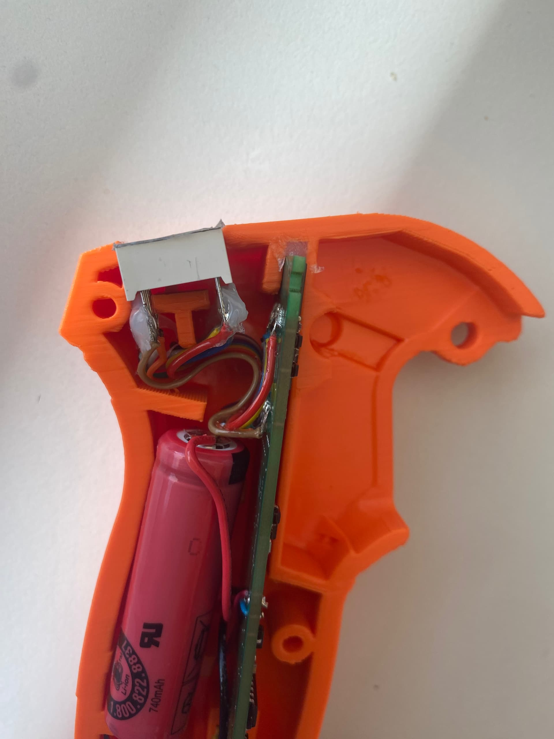
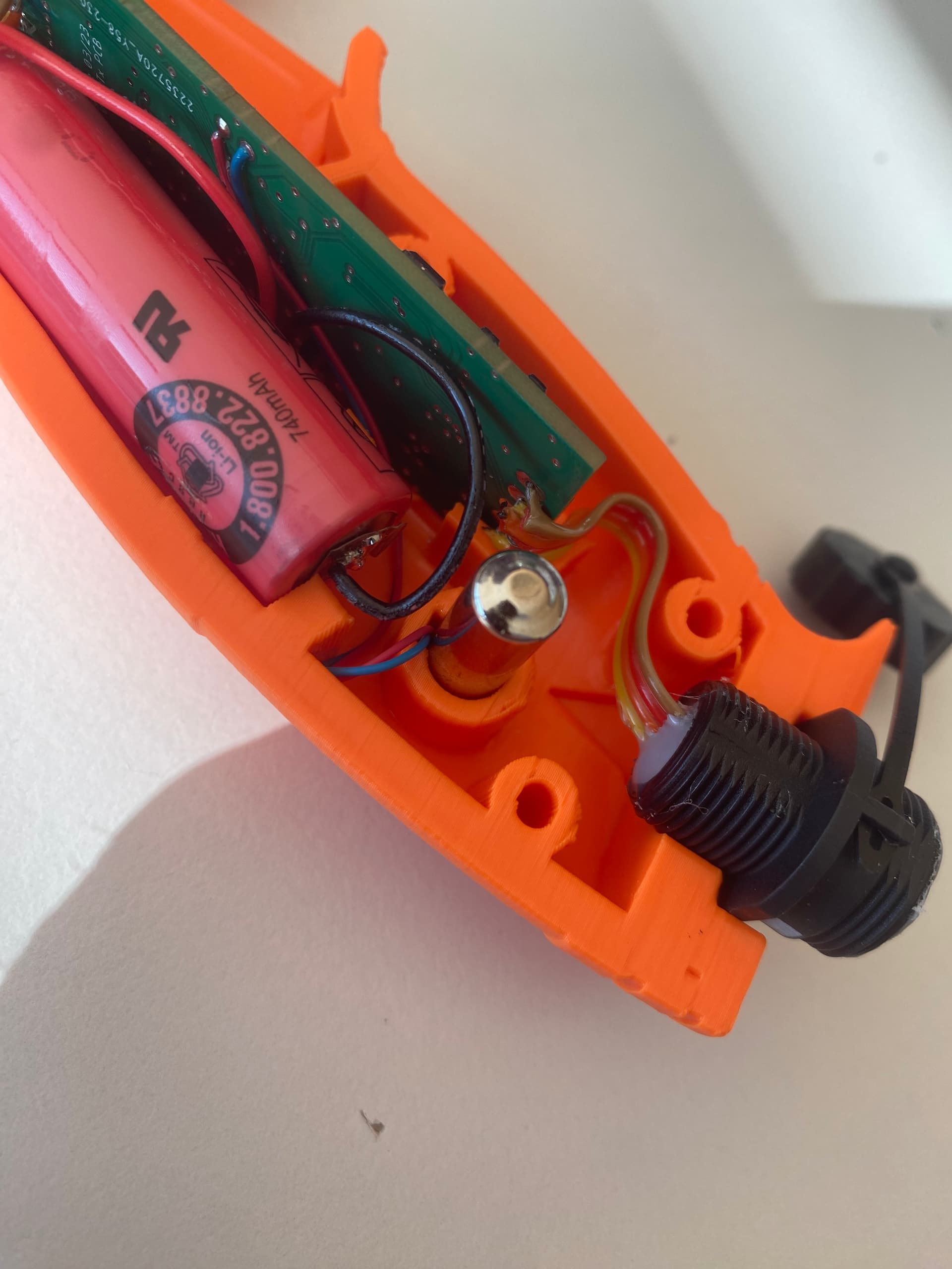
The remote usually uses 20mA so the 14500 cell with 700mAh should last a good 20-30h on-time.
Off-current is 5uA (0.005mA) so also a long Standby life (multiple years)
2 Likes
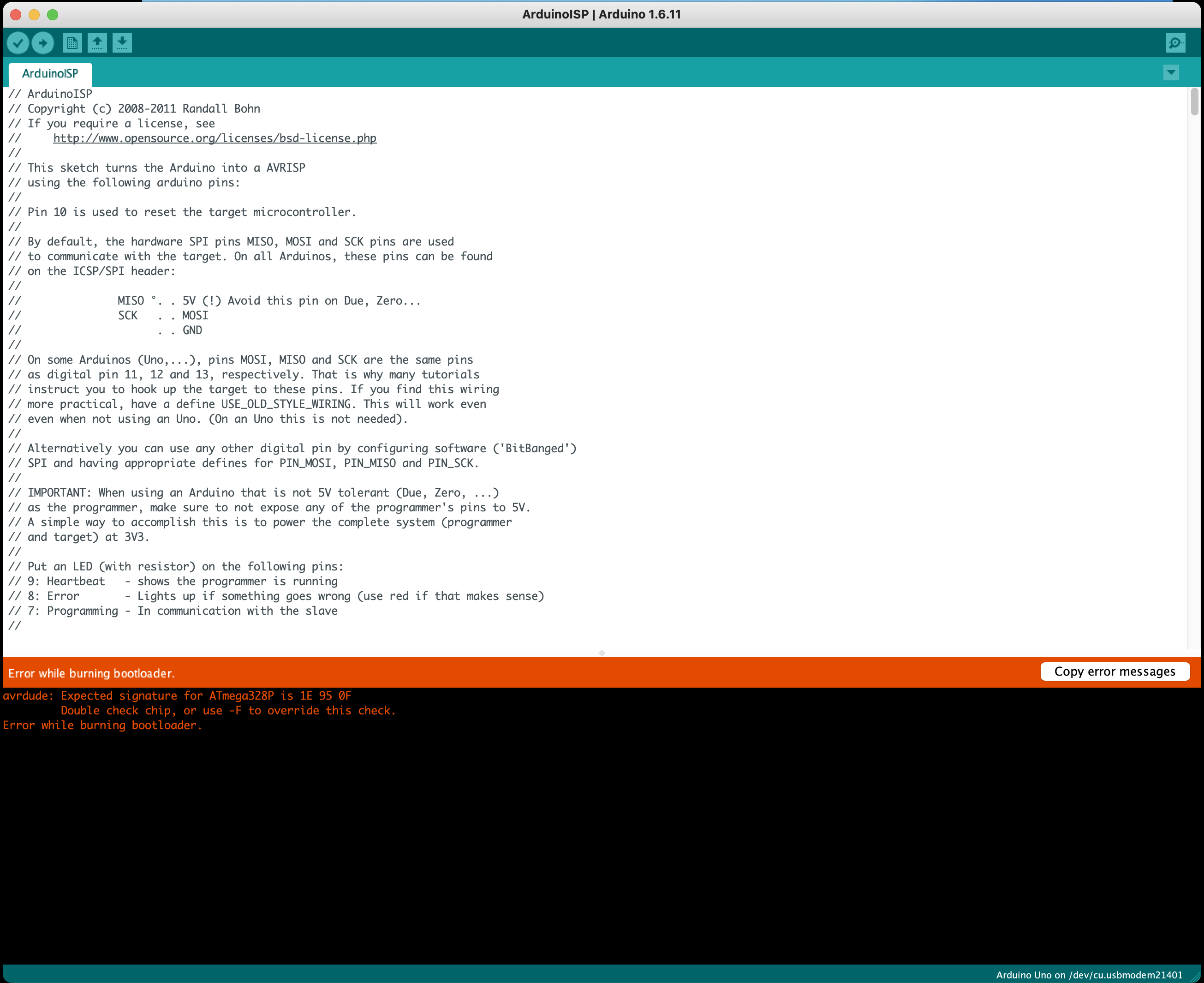
I get this message when trying to flash bootloader to the receiver:
avrdude: Expected signature for ATmega328P is 1E 95 0F
Double check chip, or use -F to override this check.
Failed chip erase: uploading error: exit status 1
I am using this board to flash:
https://www.amazon.com/dp/B01EWOE0UU?psc=1&ref=ppx_yo2ov_dt_b_product_details
Any ideas?

why dont you simply flash it using the usb connector and ardu IDE?
Ludwig flashed the bootloader to the controller for the kits he made for the german speaking group. If the pcb was odered directly from a manufacturer, one has to flash a bootloader, see here: https://github.com/Luddi96/BREmote/tree/main/Source
2 Likes
Could be a problem specific to the arduino ide version you are using. I remember having difficulties burning a bootloader to a nano, it finally worked with ide 1.6.11 (old bootloader).
Didnt realise you could do that, thought the board needs a bootloader flashed before usb functionality is possible, I’m really out of depth here so making assumptions.
Im gonna try downgrade to 1.6.11 like sat_be suggested and see if that works, if not ill try with usb, but you cant use that method with the TX.
Thanks for the suggestion ill give it a go and report back
Nope I downgraded the software to 1.6.11 and get these:
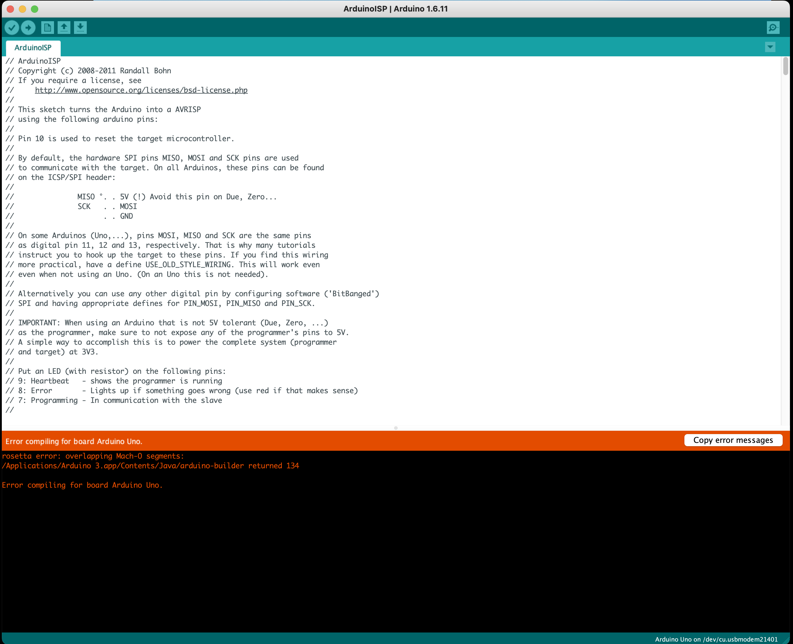
Is it possible that the Uno i am using has an ATMega8U2 chip and the Rx/Tx uses the ATmega328P and you cant use a different chip to flash a bootloader to another? I know nothing about this stuff, I just try follow the tutorials step by step but their is not much info on the “flashing bootloader” part.
As @sat_be already clarified, when the board is fresh from the manufacturer, the ATMega is empty. To enable USB capabilities, it needs a bootloader initially. For you, @Toto44 I did all that work already. But everyone else needs to once flash through SPI…
Can you try this Bootloader Flashing Tool?
It’s standalone, so just upload to the black Arduino and open Serial Port so see what happens.
If it does not work, contact me privately, then we will solve the problem and write the solution here to keep the thread readable ![]()
Really appreciate your help, I will try the tool now.
1 Like
Short update:
@freefoil and I were able to solve the problem.
The main problem is the voltages: While he used the 3.3V to supply the Rx Board, the Arduino still uses 5V on the data lines (Pins 10 to 13). While this can work, using a 3.3V modded Arduino or level shifter is the safe idea.
The device signature reported was always different, which means there was bad communication.
By trying a few times and touching the board with his fingers, he was able to flash the bootloader.
For anyone else trying this: Place some resistors (100 Ohms - 1kOhm) in the 4 data lines or use a level shifter or a modified Arduino. It is also not known if the 5V may damage the accelerometer IC which is also on the SPI bus at all times and only specced to 4.2V.
There is a quite good tutorial how to modify the Arduino: 3.3V Conversion | Arduino Tips, Tricks, and Techniques | Adafruit Learning System
2 Likes
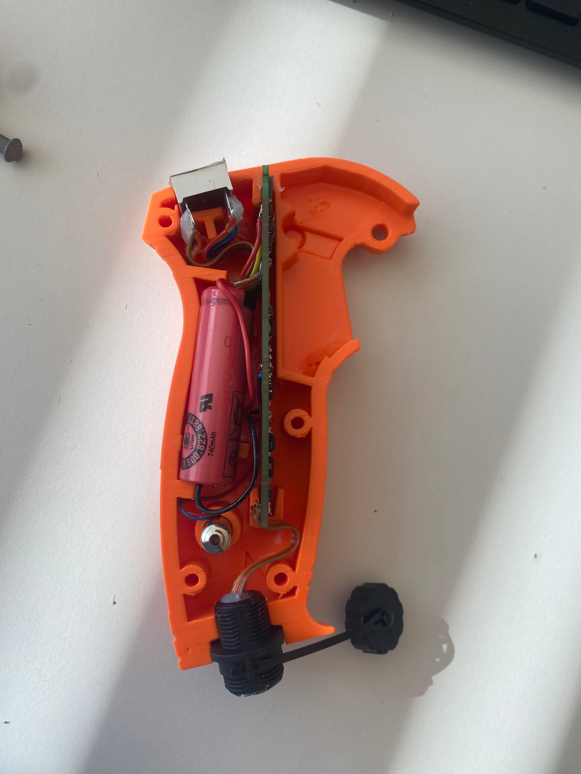
@Toto44 Curious about the working of your 3D housing for the BRemote. Can you share a video or inside picture from the model?
On the Cults3D page (link above) you can see images from inside and outside
Another Update:
On top of the steering with a servo, I have added differential steering capability to the Rx firmware. That means you can connect two seperate VESC + Motors and steering will be done by slowing down either motor
Still experimental, if you are interested, contact me via message.
10 Likes