Okay. The Rx polls the VESC every second. When it gets no response it sends the “error” message on serial monitor. So also when no UART connected. Try swapping Rx and Tx again, you should get some “CRC NOK” and “.” in the serial monitor if there is any UART connection to the VESC.
updated it like this. It could be non-related, but now it seems to be working worse then compared to how it worked before I adjusted it. I will adjust back to how it originally was in hopes it will help.
Quite sure I found the reason for the odd timings. First measured the output signal from the Receiver without VESC connected; https://photos.app.goo.gl/VszSVpa7SwD78LDS8 Then I connected the VESC, look at that pulse!! https://photos.app.goo.gl/z2MTDSqb8YDeKc6V6 No surprise I get the timings I see in the VESC.
I also connected the Maytech receiver to compare; https://photos.app.goo.gl/VZsz2i1pC4EvpNxd7
I guess the input capacitance is too high on the VESC or the BRemote output has little too high output impedance. Think I might have some driver chips to put in between.
Also guess there is a similar situation for the UART?
UART should have high strength drivers compared
If you feel like SMD soldering you can also change a resistor to improve the PPM signal?
Finally got the UART to work as well. In all the debugging of the throttle I had setup the VESC for PPM only so not very strange that it did not work. Once I turned on PPM and UART I got charge and temperature.
One thing I noticed is that I needed to connect TX<->TX and RX<->RX and not as I am used ot RX<->TX and TX<->RX. On the Maytech receiver it is the later and lots of other UARTS I have used before.
Is the a RSSI from the NRF? Then I might make some code contribution to show that as well.
Thanks for all the support!! Really helped me a lot!
Nope, NRF does not provide any form of RSSI. One of the reasons V2 will have a different module.
Ooh interesting! Any more details you want to share?
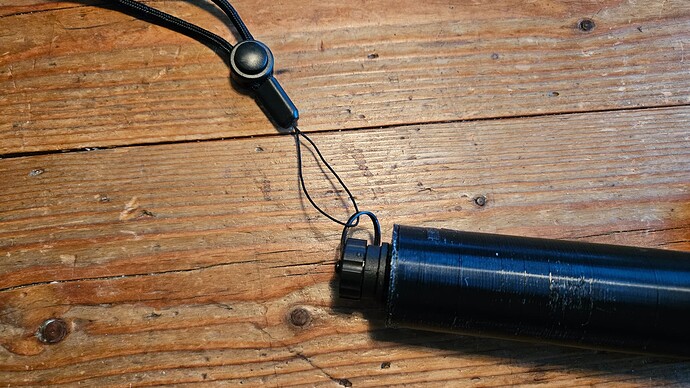
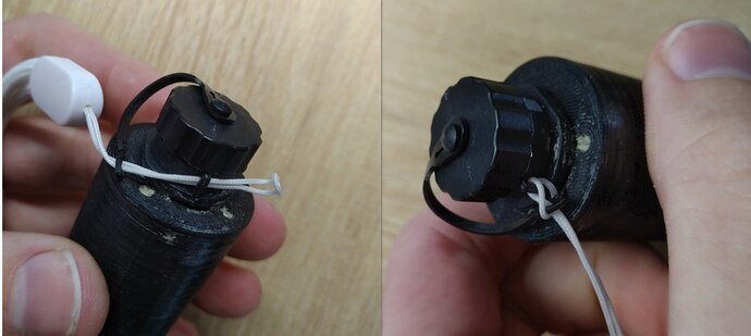
By the way, a final question for now. How do you mount the leash?
Like this? Feels like it could snap off easily in a hard crash, or?
Had the same problem, any solution to fix it? THX olli
I am not 100% sure of the root cause yet… the foam does not seem to be the (only) cause:
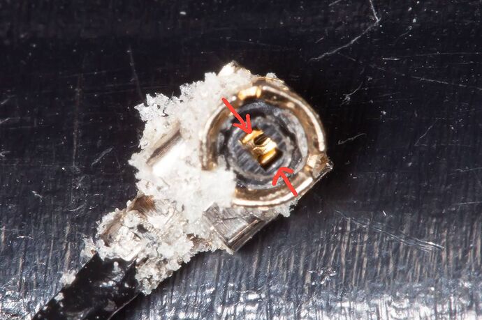
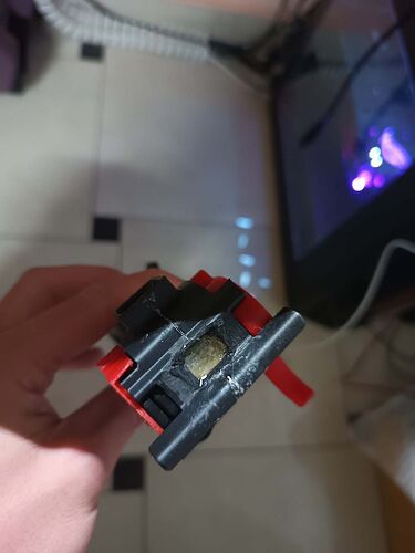
Apparently some of the antenna connectors have a bad contact due to the fact that the contact are bent too far apart:
My current way of repairing this is to cut out a rectangle where the “fill nipple” is, then dig through the foam, unplug the connector and bend the pins back together…
I think in your case the best would be to send back the defective remote in exchange for a new kit? If so, please contact Jasmin from openfoil for the details on sending back. You can also try to repair yourself of course.
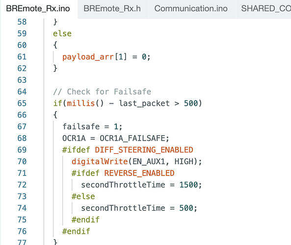
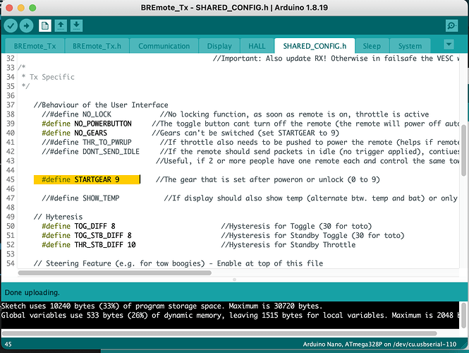
my carbon board has RF connection and stability issues leading to E4 error condition. So Inwant to configure BREmote so it defaults to L6 as starting gear, and when E4 error happens as well.
(With E4 connection issue BREmote keeps downshifting to lower gears and I am spending so much time just trying to get to L6 and enough connection to launch).
super easy. Line 45 of the shared.config in the TX file you can set the start gear to whatever you want. Just change the 9 to 6 for level 6
nice! Thank you!! ![]()
Have you tried to solve the connection issues? I do not have experience with the Bremote regarding that but some with a Maytech remote. And one thing I had done by mistake was to place the receiver board near the motor cables. The rf environment close to them is horrible and there is lots of interference. Could you have a similar situation?
Yes I tried many things—installed SMA142 low loss insulated coax all the way from isolated box (located far away from motor cables) into the the front port of my (Lift 4’9”) board. I also carefully spliced and soldered the antenna directly onto SMA142 coax to avoid db loss from couplers. After making these changes It works better but it still is barely rideable. Before I made these changes I couldn’t get prop to spin if the board was in water. I really don’t know what to try next…
One thing you can try - add a 1kOhm resistor between battery GND and the carbon board.
Sometimes the whole board becomes a big “antenna” for the ESCs emissions and disturbes everything around it. This is especially a problem for carbon boards.
I like your thinking! Now my challenge is to electrically tap the CF layer in a finished commercial Lift board. There is a tiny hole with a round sticker over it I believe it is a vent of sorts. Maybe screwing into that with a tiny tap then sealing it with silicon sealant. Or that vent may be important to keep as-is… hmm…
I had a friend who found this out with his diy all-carbon board and it really helped
The mast screws, hinge screws, etc. may also be a good place to attach the connection
The existing holes must tap to the carbon layer and that’s way better than creating new ones. Good stuff. I’ll report back in a few weeks if it helped. Cheers.
Is there a reason to use this specific PU foam?
