Maybe it will seal by being squished upon the walls after expansion …
Sounds like a problem with the drive strength of the Rx… The ESC is opto isolated, so you will likely need to provide 5V as well as PWM and GND
Do you have an BEC in the system? How is everything connected?
OK. Yes, I have a BEC connected since the ESC does not have a BEC. I have connected the Matek Micro BEC from the battery to the Rx. From the ESC to the Rx, two connections are made: SRV and GND. I’ve followed the Connection Example diagram provided under ESC or VESC WITHOUT UART.
Can you also connect the 5V between ESC and Rx?
I had asked Hobbywing Support about connecting 5V between the FlyFun HV 160A ESC and the Rx. I’m told there is no way to make that connection. They continue to recommend setting the signal. …and then suggest swapping the PMM signal for a PWM signal as this ESC was intended to be used with a PWM.
Hmm in the manual I see two servo connectors, one has only signal+gnd, the other one all 3
Can you share a picture?
PPM and PWM in eFoil is the same
Another thing you can try is increasing the pullup on the signal wire, add a 1kOhm resistor between the 5V and the SIG pin on the Rx
We had this problem with a similar ESC already, timing and signal shape was not the problem but input resistance of the ESC…
Thanks. Yes. Here’s the FlyFun 160A “Product Extra Information”. …the documentation shipped with the ESC was incorrect, as this ESC does not have a BEC. Anyways, this is the updated documentation:
The 3 wires are only used for programming the ESC. The black and white two wire pair are the ground and signal wires.
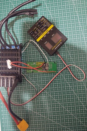
Here’s an image of the ESC, Rx, and Program Card:
Ahh okay got it
Ok, let’s proceed with adding a 1000 Ohm Resistor between 5V output of BEC and the white signal connection
What kind of measurement equipment do you have? Multimeter? Oscilloscope maybe?
OK. Sounds good. I have both. I’ll proceed with adding the 1000 Ohm resistor.
If you have the oscilloscope handy, you may measure the ESC signal (white wire) to GND
Just send a picture of the waveform here.
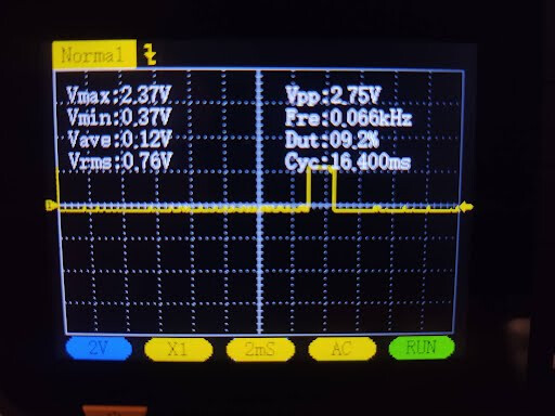
Here’s the measurement with no throttle:
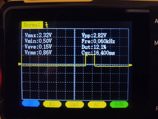
and full throttle:
Ok, that looks good.
And with the resistor also no luck getting it to work?
Lastly for the timing, in BREmote_Rx.h change following values:
Lines 85 and 92
OCR1A_MID to 2000
OCR1A_MULTIPLIER to 3 or 4
Which exact timing does HK require?
Does that mean the full span of duty cycle used is from 9-12% with this signal? Isn’t it too little, i would’ve guessed at least a span of 50-100% higher at full throttle
(but i don’t know what’s normal here)
For the PWM of remote remote control timing is
1ms to 2ms of ok time (1000us to 2000us)
Sorry if this is a stupid question but this is what i thought, signal length ON is 200% of no throttle at full throttle (2/1) but duty cycle relation on pic is only 132% (12.1/9.2)?
I don’t understand the 200% thing
The frequency is 60Hz
So a period is 16.6ms long
And 12% of 16.6ms is exactly 2ms (2000us) so full throttle.
And with the settings from the picture (default) the low throttle is 9% or 1.5ms (1500us)
Changing the OCR1A value to 2000 should result in 1000us no throttle value
There is no real standard, but in RC usually 1000us if full reverse, 1500 is neutral and 2000 is full forward, that’s why I used this for the default configuration
2 Likes
That explains it, thanks!
I thought full throttle 2ms, no throttle 1ms, that’s an increase of 100% ON time
(frequency doesn’t matter as the same OFF time comes into the equation both for neutral and high when dividing duty cycle percents, this was what i was basing my question on.)
1 Like
Apologies for any confusion. Those images were before the resistor was connected. I’ve since added the resistor and tested without luck. I then changed Lines 85 and 92, and tested both with multiplier 3 and 4.
With respect to timing, HW stated:
"the signal needed for the throttle signal is the Futaba Standard PWM Signal.
50Hz with a range of 1100-1940µs (0 throttle-100% throttle)."
1100-1940 should be achieved with
Ocr1a mid 2200
Multiplier 3

According to my information futaba needs different timing
This would result in
Ocr1a mid 1900
Multi 3
2 Likes
So, I took the boogie out today. Fully charged 12s battery and it was only showing 50% on the remote. It was working fine last time I used it. I am using UBAT and triple checked the code. I swapped this RX onto another boogie with a full charge that shows 95+% on the remote and same thing. I also tried a different BREmote with this RX board and same outcome. Any ideas?
I also checked the voltage at the wire connected to UBAT and it was 50 volts.