Yes that would help
The Rx needs 50mA tops, and the two ESCs should not consume any power. As long as you don’t have the servo to steer 400mA is enough
Yes that would help
The Rx needs 50mA tops, and the two ESCs should not consume any power. As long as you don’t have the servo to steer 400mA is enough
Hey @ludwig_bre, do you think you could update the step assy to include the LR parts? I’m building one and want to see the total. Pretty please ![]() ?
?
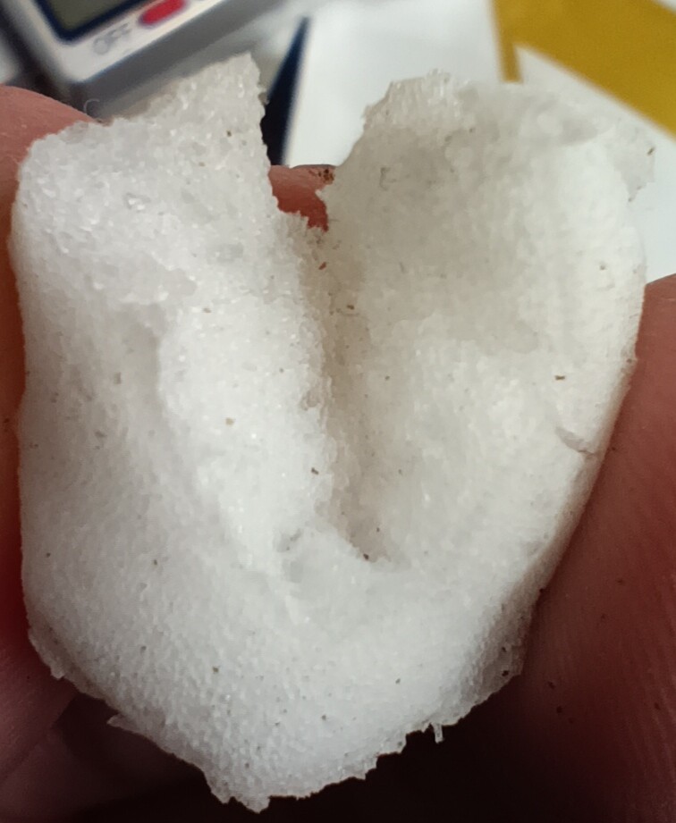
I received Soma Foama 25.
It looks and feels fine, glued to petg and it doesn’t absorb water. However, the working time is quite short—only 1.5 minutes, with 60 seconds for mixing and 30 seconds for pouring, leaving little time to address any bubbles.
It only expands to about x2 its original size in a few minutes.
Let me know if you’d like to see some experiments with it.
Hmm, I dont have the step files of the newest LR parts, as a friend designed them and we only shared .stl files
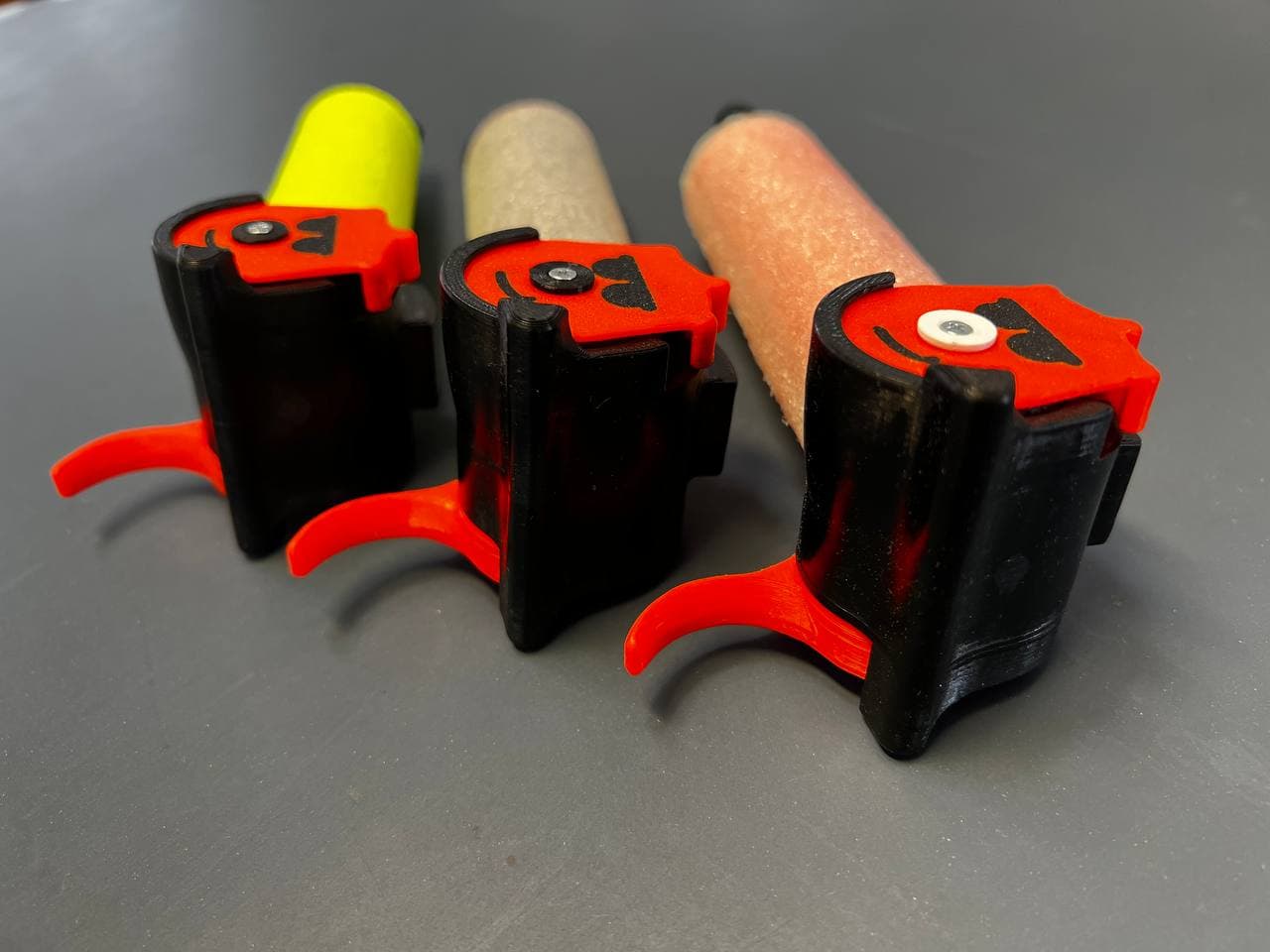
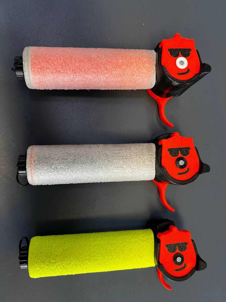
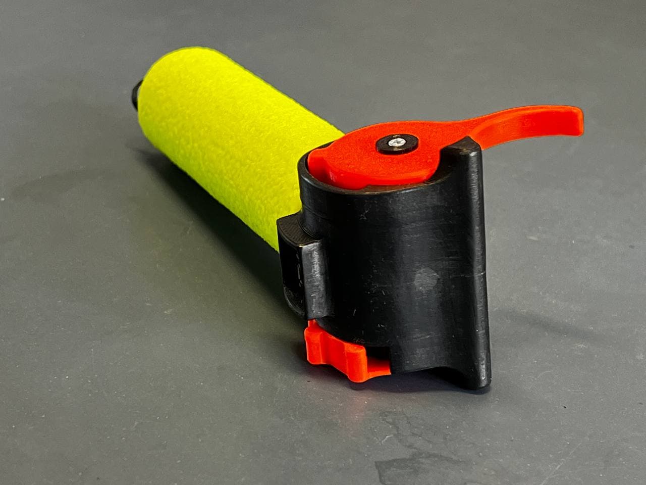
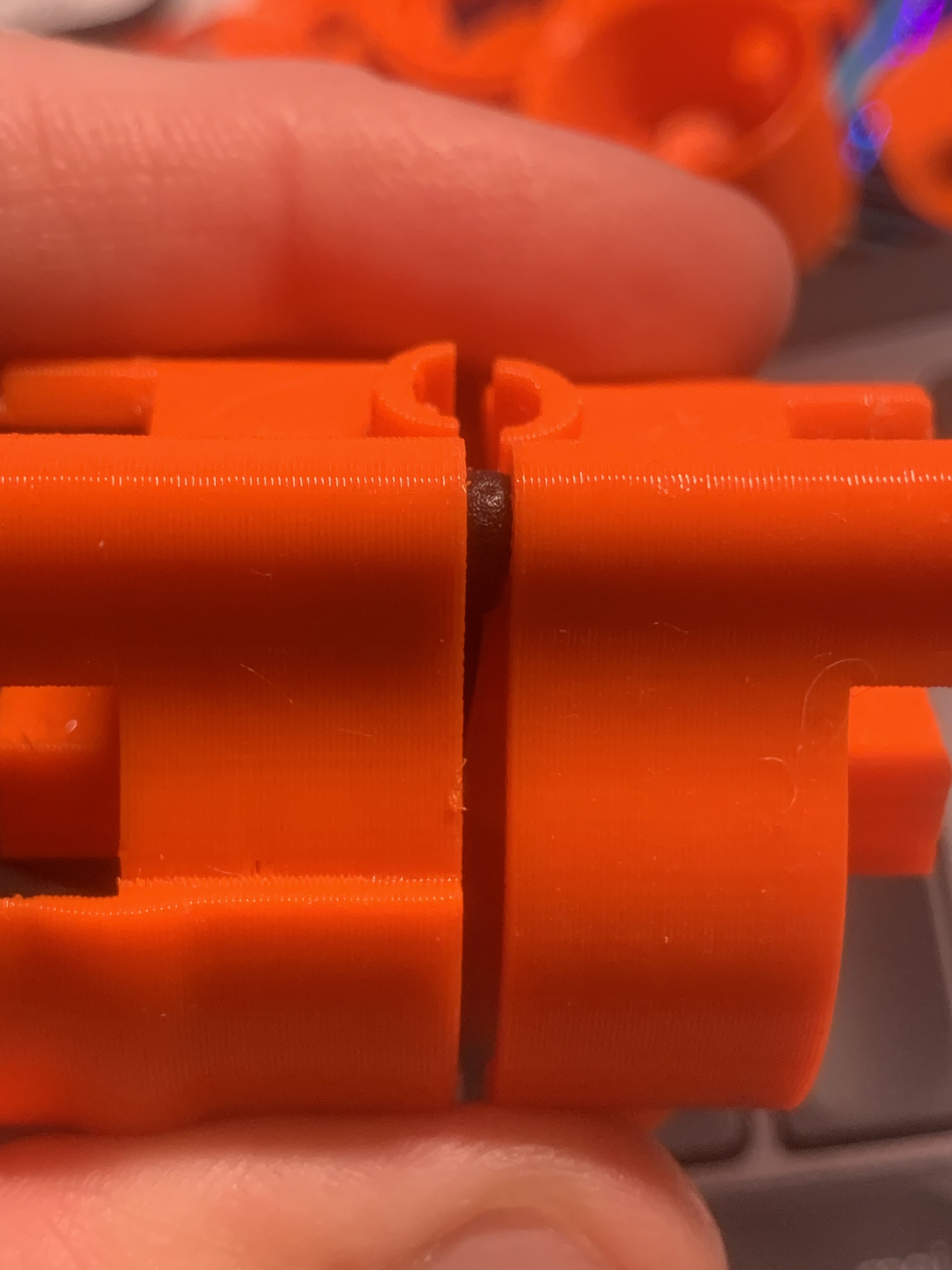
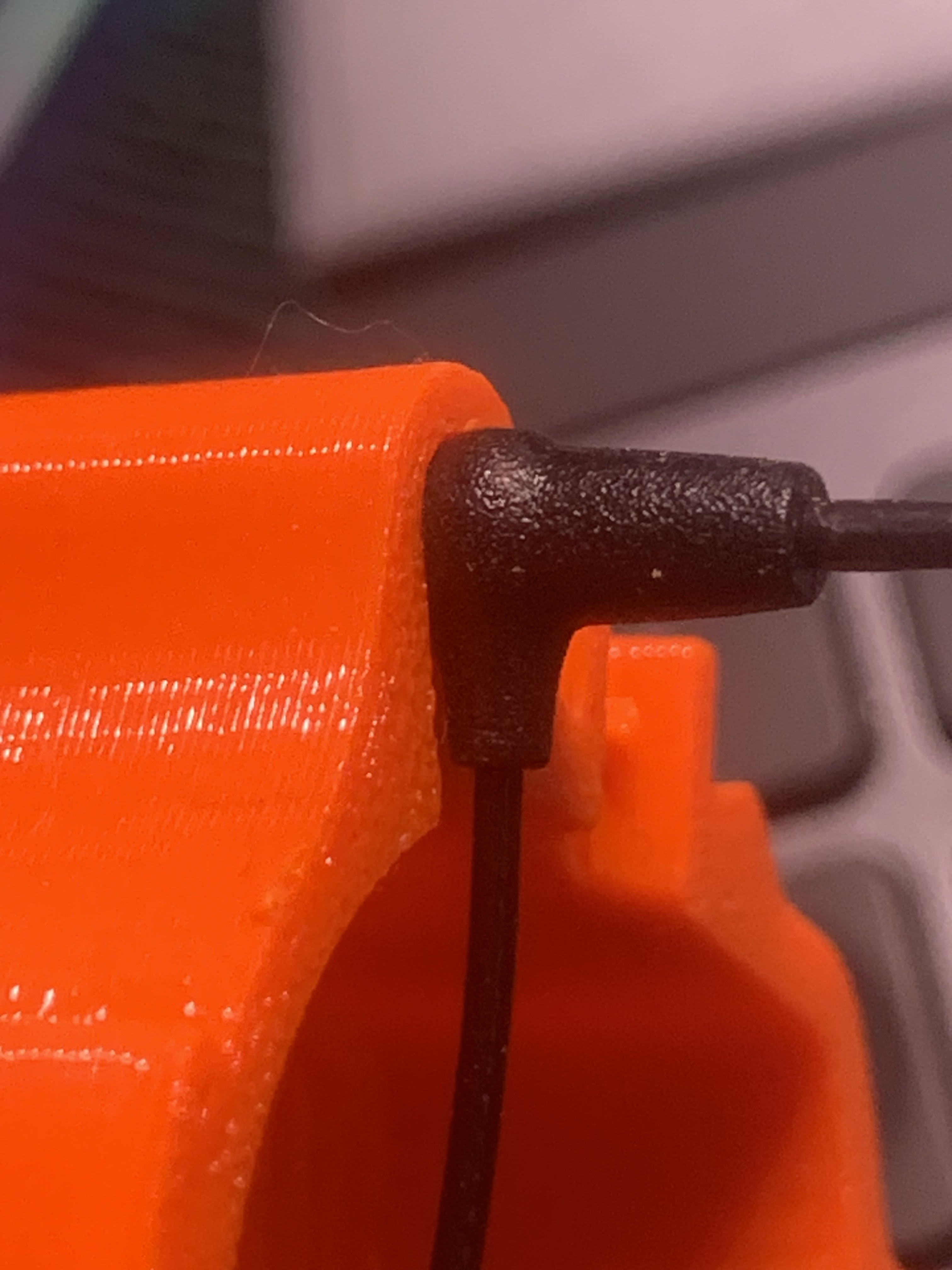
Here are some real-world pictures:
I mean I could probably do it, which software have you been working on this model with, if it’s onshape it should be fairly simple to share the design.
I could redesign them from the stls i guess… hate working with stls, even converted ones.
I understood you just want to see the final assembly? Why the effort?
Old habits i guess. 3d-printing an assy is so, i don’t know, uninvolved? I like to look at the parts, see if it’s got some improvements that could be done, see why it was designed the way it was, stuff like that.
Understood
I asked the friend if he has some steps
EDIT: He has: (right click → save as)
https://lbre.de/fs/20240709_long_steer.step
Fusion 360
Post must be…
There are some improvements in the files, too bad i already did similar changes ![]()
These steps / STL:s should be the base for the Bremote LR in my opinion and be included in the git
Yes, I already assumed they have advantages
However I like to test stuff before putting it to the git, which I did not have time for yet ![]()
There are things to improve in them for sure so i agree with you. If you want to i can send some updated files and comments in PM
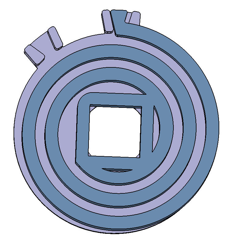
I made a stronger spring for the Bremote toggle side. It gives you a firmer toggle and less unintended activations. I know the new toggle disc model looks really flimsy, a flat plate with no side walls but this was designed to fit the thicker spring with same outer diameter and reduce friction points - it’s stiff enough.
I haven’t done test cycles with it (like Ludwig with the original) but it works well so far.
Regarding bremote Rx setup:
I had the same question as @seagull_nz when updating the Rx file on my build. If you strike out the VESC line and set UBAT line like this (to fit an ESC without UART):
//#define USE_VESC_UART
#define USE_UBAT_MEAS
Then there is no check for UART communication and hence serial monitor doesn’t show “message error” being sent the way it does in the instruction video. At least that’s what i think happens?
@ludwig_bre might be good to comment this in the video or in the documentation since this question will probably come many times more ![]()
Hi everyone,
I have two base bremote boards. One of them works perfectly with the remote connection. I turn it off and try to connect the remote to the other board, but E4 appears.
Is it a wiring problem on my part or once the remote is paired to a motherboard, do I have to do something to pair it to another motherboard?
Thanks
So you have one Rx running, and one Tx can connect but the other can’t?
Which kind of Tx boards? LR or standard range?
Did you set the correct/same addresses in the SHARED CONFIG?
thanks for your answer;
The motherboard that connects to the receiver is a V1.3 rx PCB, and the other one is also a V1.3 rx PCB prepared for dual motor, bought already with the resistance configuration.
I have not done any configuration yet. I guess that’s it.