super thanks Jasmin.
I’m just building a bremote, i see the there’s no instruction to glue handle to head and handle to USB connector cap in the build video - is the foam normally enough to keep the bremote parts together?
I don’t have the best fit, especially on the handle to head since my printer struggles with supports. I’m therefore glueing it.
Edit: looks glued here in the video, maybe Ludwig just forgot to mention it
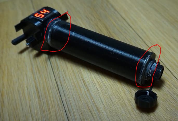
Some I glued, some I did not
If you have a gap, make sure to fill it with some kind of glue, so the foam does not get out
Stucturally 90% comes from the foam once its hardened
Hey Ludwig,
I think it would be useful if we could see the battery charge percentage while charging. Would this be possible to code in somehow?
Thanks.
In V1 there is no clean way to implement this… only solution is to briefly turn the remote on to see the state of charge.
Will implement this in V2.
Thanks Ludwig appreciate it anyway.
Hi @ludwig_bre I would like some clarification - I need your help:
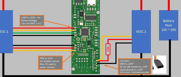
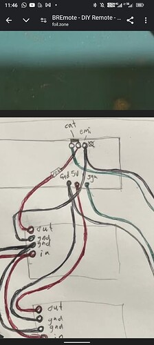
1/ For 2 VESC, you need to solder like this: could you confirm ?
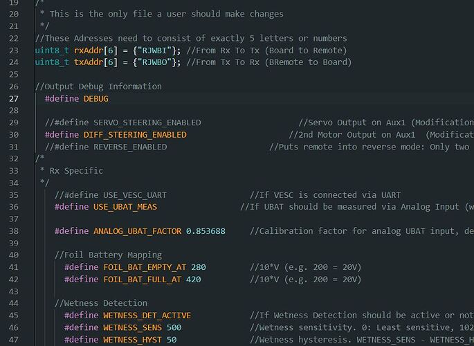
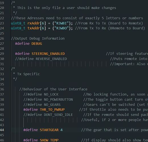
and activate ’ #define STEERING_ENABLED ’ in BREmote_Tx + #define DIFF_STEERING_ENABLED in BRemote_RX.
I read this comment ![]()
“…on AUX 1…” for SERVO_STEERING_ENABLED (SERVO) and DIFF_STEERING_ENABLED (2 motors via PWM VESC). On your video with servo, we see clearly that AUX1 is use (https://youtu.be/DhPk98Wdcn0?t=97).
Then:
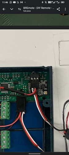
On this schema, we see EMI and CAT used and not AUX1.
I have no output PWM on CAT with oscilloscope.
Could tou help me to have correct wiring/soldering
1/ If I want 2VESC CAT + EMI ?
2/ If I want 2 servo control: AUX/NC/GND ?
Thanks !
For all type of control, Emi/Cat should be used as 2nd output. Your wiring looks correct.
You can only measure PWM on the CAT if the VESC is connected to this output and turned on, as it needs to provide the 5V isolated supply. If you use an ESC, that does not put out 5V, you need an additional BEC on top.
If you use a servo, you also need a BEC for that Servo. And change another line of code in the BREmote.h file
Line 103, following change to
#ifdef SERVO_STEERING_ENABLED
  #define EN_AUX1 A2
  #define EN_AUX2 A1
I miss the 5V isolated supply ! ![]()
In last release code on github, in BREmote_Rx.h file: we already have this which must be activated when SERVO_STEERING_ENABLED or DIFF_STEERING_ENABLED
#ifdef SERVO_STEERING_ENABLED
  #define EN_AUX1 A1
  #define EN_AUX2 A2
#endif
#ifdef DIFF_STEERING_ENABLED
  #define EN_AUX1 A2
  #define EN_AUX2 A1
#endif
(A2 and A1 pin seems reversed in what you wrote ? ![]() )
)
Thanks ! it’s works now with 5V IN! ![]()
Exactly, so please reverse like I wrote in order to use a Servo on the Emi/cat
Great ! Thanks for the confirmation ![]()
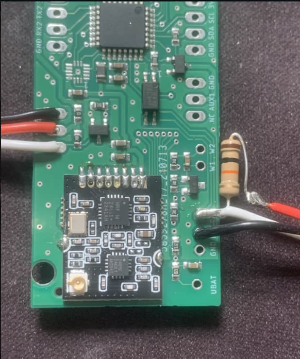
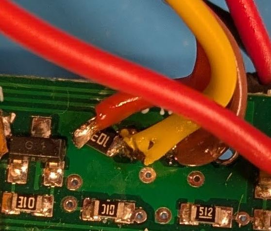
Here is what mine looked like under the blob, A tiny resistor marked ‘103’, which Google tells me is a 10k resistor.
About this, I’m troubleshooting getting no motor rotation from the cat/EMI side. Both motors/ESCs work as I can swap the servo cables and get each motor spinning from the SRV/5V/GND side). I’ve continuity tested tested my wiring and all looks good, but I’m getting nothing testing across the 10k resistor which is consistent with testing against a new standalone 10k resistor.
Any other suggestions for troubleshooting? The steering appears to be enabled because the motor speeds up and slows down when I’m ‘steering’ on the Tx with a constant throttle.
Can you post the contents of the shared config of the Rx, TX as well as the rough schematic of your build?
Ah you beat me to it! I think I didn’t enable steering in the Tx, it was just the Levels going up and down on a constant throttle that was changing the speed, I’m updating now. ![]()
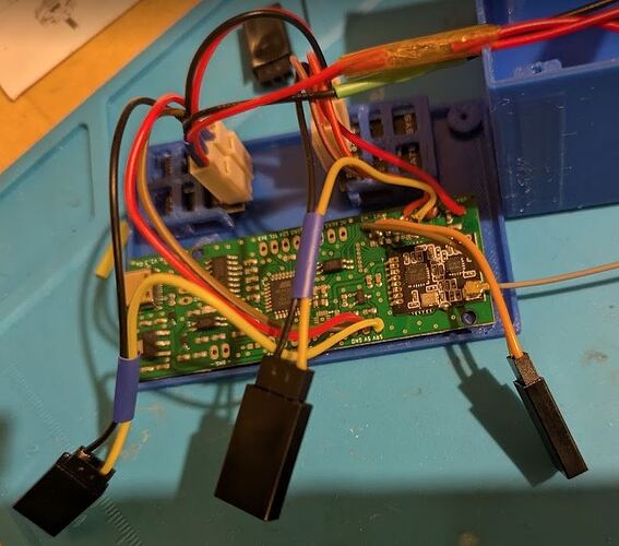
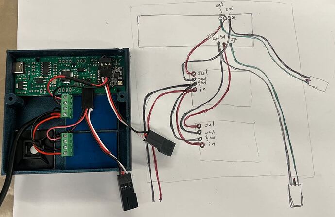
Ah that didn’t solve it. Here is a photo of my spaghetti, which I wired up from @Larsb example, as pictured, Followed by my shared configs.
I think only one of my ESCs is giving me an “Armed” beep when I power the system.
Any suggestions for troubleshooting greatly appreciated, your videos and help guides were amazing for me to get this far!
This looks wrong
The red wire needs to be left, through the resistor and white needs to be in the middle and connected directly
Anyway, for your setup you can try changing the resistor from 5V to cat to a 1kOhm resistor
My routing can be confusing on the pic as it doesn’t show how the wires are connected but red has the resistor in the wire from the bec (visible on pic) and red and white pins are bridged/connected and white pin header is cut off at the lower end / is not connected to the board since there’s no hole there on the pcb. This way white is directly connected.
It’s explained in my tow thread. I think the connection i made is correct?
Ahh got it
Yes then it’s correct
Thanks. I think one of the BEC connectors might not be reliable. I’ll re-do it over the weekend and post an update then. Thanks again for your help.
Got it running now ![]() . I’m so grateful to everyone on here I wouldn’t have dreamed of doing a project like this without all the great info, and of course the ability to steer a boogie opens up so many possibilities.
. I’m so grateful to everyone on here I wouldn’t have dreamed of doing a project like this without all the great info, and of course the ability to steer a boogie opens up so many possibilities.
