Get an idea how much I use when I go for a long cruise, keep an eye on things when wind pickup, tidal flow increase ect.
Also use on calm day to tune a new rear wing angle, there is always a sweet spot pitch stability/drag consumption per kilometer would be even better for that
3 Likes
Another information on the LR:
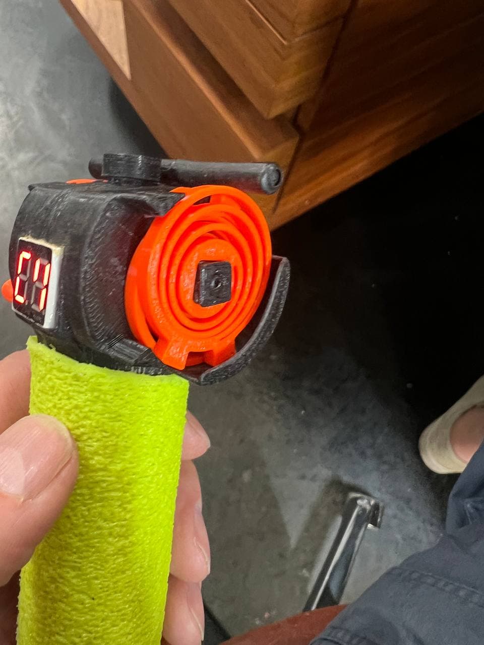
My original design has the antenna sticking out of the casing - that is a potential breaking point when handling the remote.
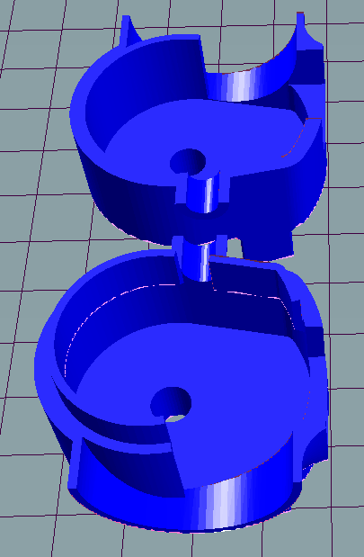
So I am very happy a friend, Jürgen, designed a different body for the remote with the antenna integrated. He also added a small wall to the toggle side to avoid accidentally rotating that (img 3) - if you dont want that just mirror the other part.
GitHub
Here already some images:
4 Likes
Hi Ludwig,
I’m trying to design my own housing for the remote. Since I have not printed the housing parts or built one yet, I’m trying to understand the required orientation of the magnets, type of magnets recommended, and how far above the PCB the magnets are allowed to be.
Thanks, Scot
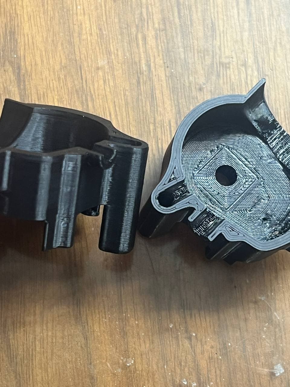
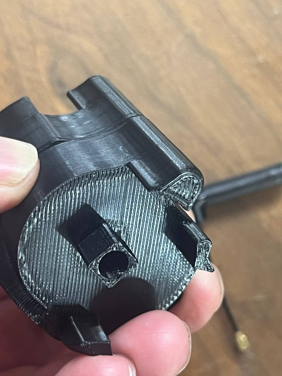
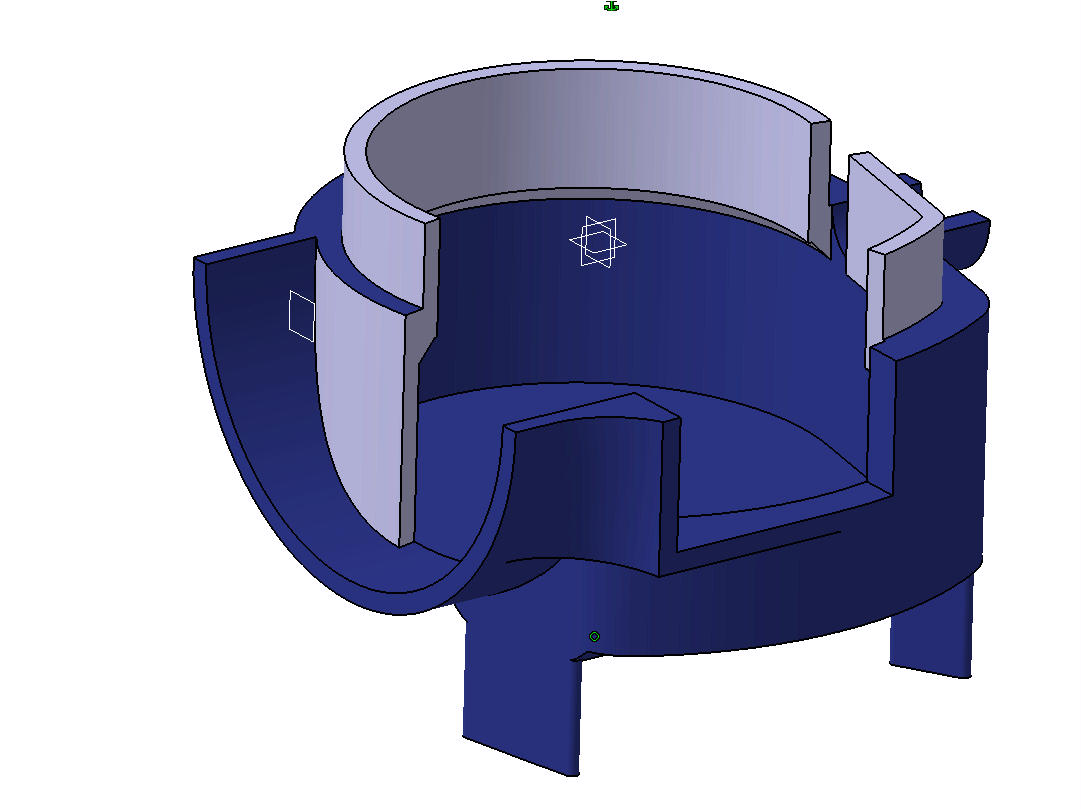
I just started building my kit but got some issues, the magnet covers are so closely fitting that you need to be very careful not to get any adhesive on the magnet stalk, of course i did…
I redesigned the covers to get more clearance, the oval “end stop” is removed but couldn’t really see a problem with it? I think it should any way be incorporated into the trigger or switch parts and not in this tiny interface.


What’s your input @ludwig_bre? I guess the endstop might be an aligning feature for the original position of the trigger but that could be solved with making the magnet holder base rectangular instead of square?
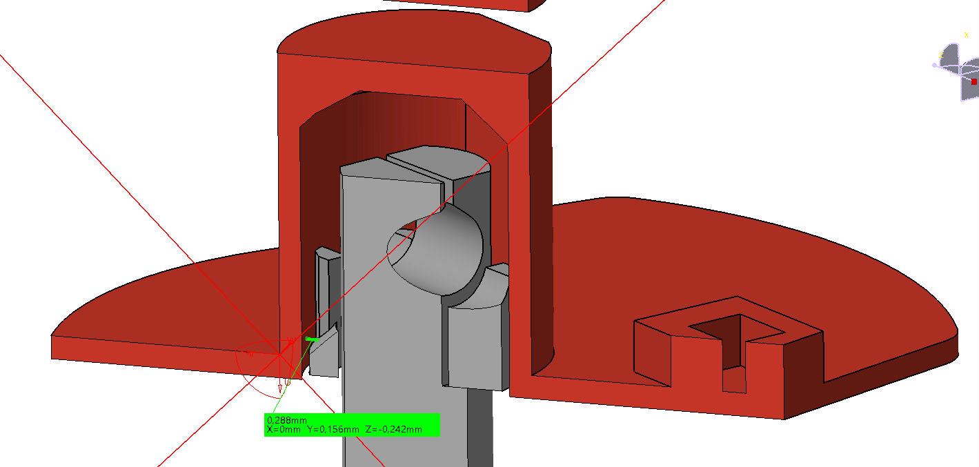
It’s not an endstop, it is to get enough clearance to the PCB. Your parts seem to be touching, keep in mind there are also components on there, that are not in your model…
I checked it on the prints, you are right, i thought the PCB CAD was complete with all the parts. I will make a small adjustment to make it work - but i think the clearance increase is an improvement to the design.
How sensitive is the magnet to PCB distance actually? will 0.5mm adjustment make a difference?
I see that the trigger to magnet holder interface makes it possible for the trigger to grip/rub on the stationary part of the remote head? It’s not fully inserted here but with the screw in place it can happen as the design is now, especially for us with crappy printers.
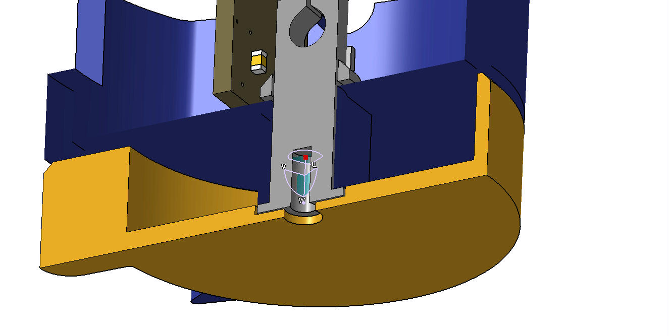

The square pad on the magnet stalk pad could be a bit thicker to stop this risk, would also make insertion a bit easier.
Distance is the usual quadratic relation, so twice the distance = 1/4th the fiel strength, so keeping the distance very short is important!
I have got a very crappy printer myself, that’s why many design aspects were made like this, to make it easy to print for as many people as possible…
I agree on this, if the magnet rod breaks then the remote won’t be fixable and there is only 5mm of material in the rod. How are your remotes holding up?
@Jatem : I wanted to use the stronger springs but needed to modify the model. Could you upload step files also to thinginverse? STL files are so tough to work on, i tried converting them but i get a lot of corrupt surfaces.
If you need original STEP files, you can download here
yes, i got them already but jatem made a stronger spring assy that i’d want to try… Thanks for the help anyway Ludwig!
By the way, i added a lip to one of the remote head halves to get both a stronger bond and less fiddly to glue. It’s printing as we speak, if it’s good then i’ll upload to thinginverse.
They need to be printed with the outside downwards, it will be a lot easier to remove the supports from this side too

On the availability of magnets for the remote:
I found 3x6 and 3x8 N48 magnets on some sites, it seems i can fit both with the redesign of the magnet covers i did.
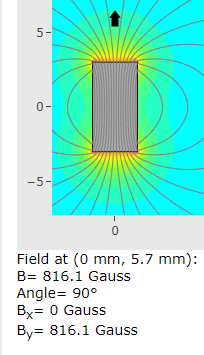
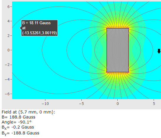
Their magnet field strengths compare like this:
3x6mm N52 @ max 851 gauss
3x6mm N52 @ side 197 gauss
3x8mm N48 @ max 1706 gauss
3x8mm N48 @ side 192 gauss
It’s 200% diff in max due to the longer magnet, 3% diff in side direction t - throttle response will be really different so i guess it’s not an option.
If the magnet used is N48 3x6mm then it’s 5% in max and 4% in side direction. This should be acceptable?
I just watched the deep dive video and i think i might have misunderstood the need for a 3.3V conversion; is this only needed if you have PCB:s without bootloader that need to be flashed with the pads??
I got a kit in may this year with bootloader on it, it would be nice to avoid changing components on the board, (please confirm).
I can confirm. 3.3v for flashing boot loader.
I think you can still use them, different magnet strength will be handled in the calibration of the remote. Only decreasing from the current magnet strength is not recommended, as this will decrease the sensitivity. Increasing is no problem as long as the magnet sensor can handle 1000Gs I think.
If you got the kit, the bootloader is already on the remote and all you need to do is connect the remote to USB. For that you don’t need a second Arduino, so there is nothing to convert to 3.3V.
1 Like
Thanks! This made my day 
I have got my remote working ok on PPM but when I try to connect it with Uart I get an E4. The green led is on. The Uart works with another remote Vx3. I do not know where to start troubleshooting
You always need to connect PPM with the BREmote. PPM provides power to the Rx and throttle signal to the VESC, UART is just for telemetry data. Please see the connection examples at the GitHub page.
1 Like