I followed your procedure and the motor turns for a few seconds and stops, and nothing more.
I am going to test with a flipsky vesc (mini v6.8)
I ll tell you.
Thank you.
Hi Ludwig,
I fried another RX today it shorted when I plugged battery in I think I had some moisture on one of the plugs
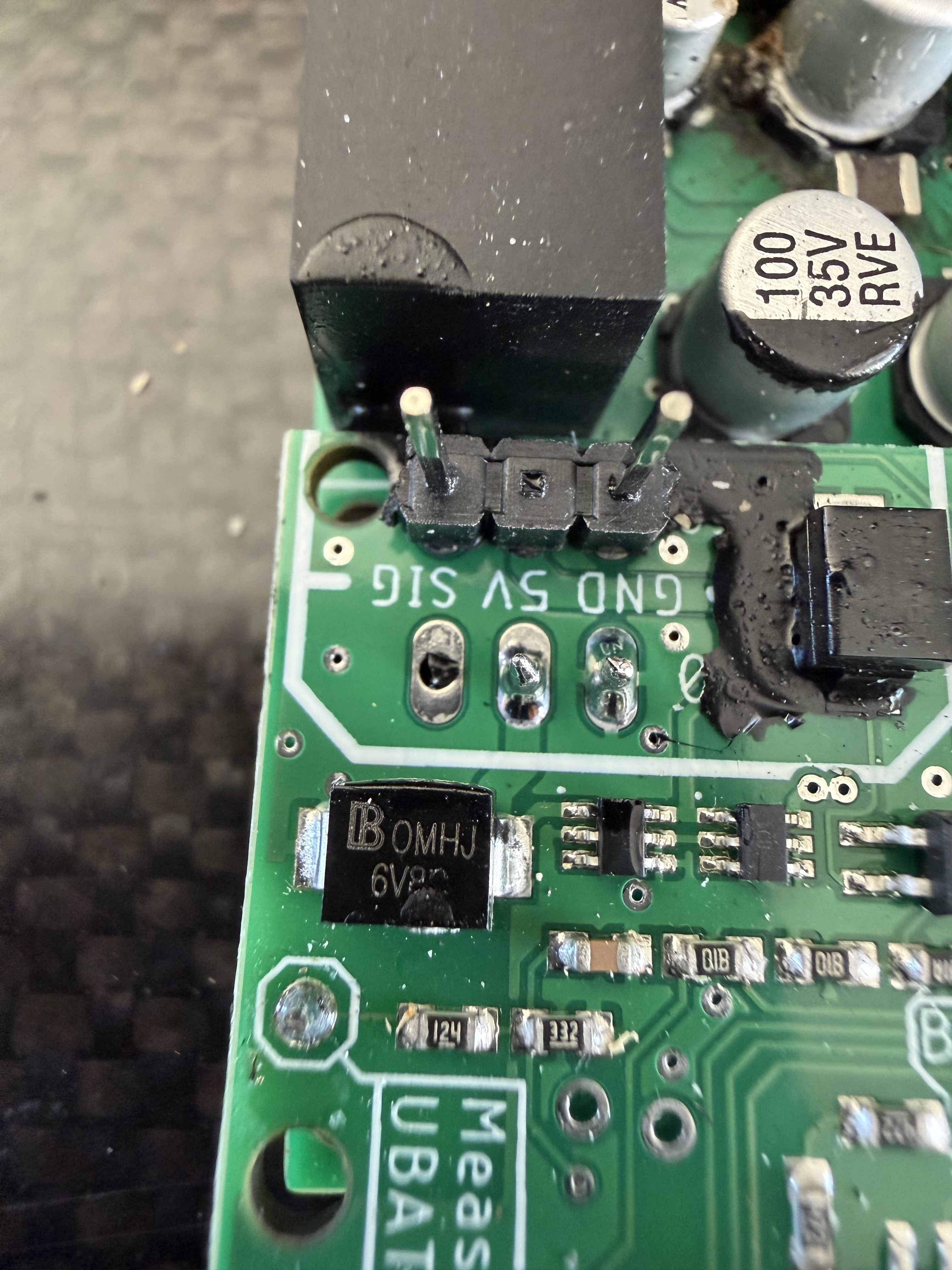
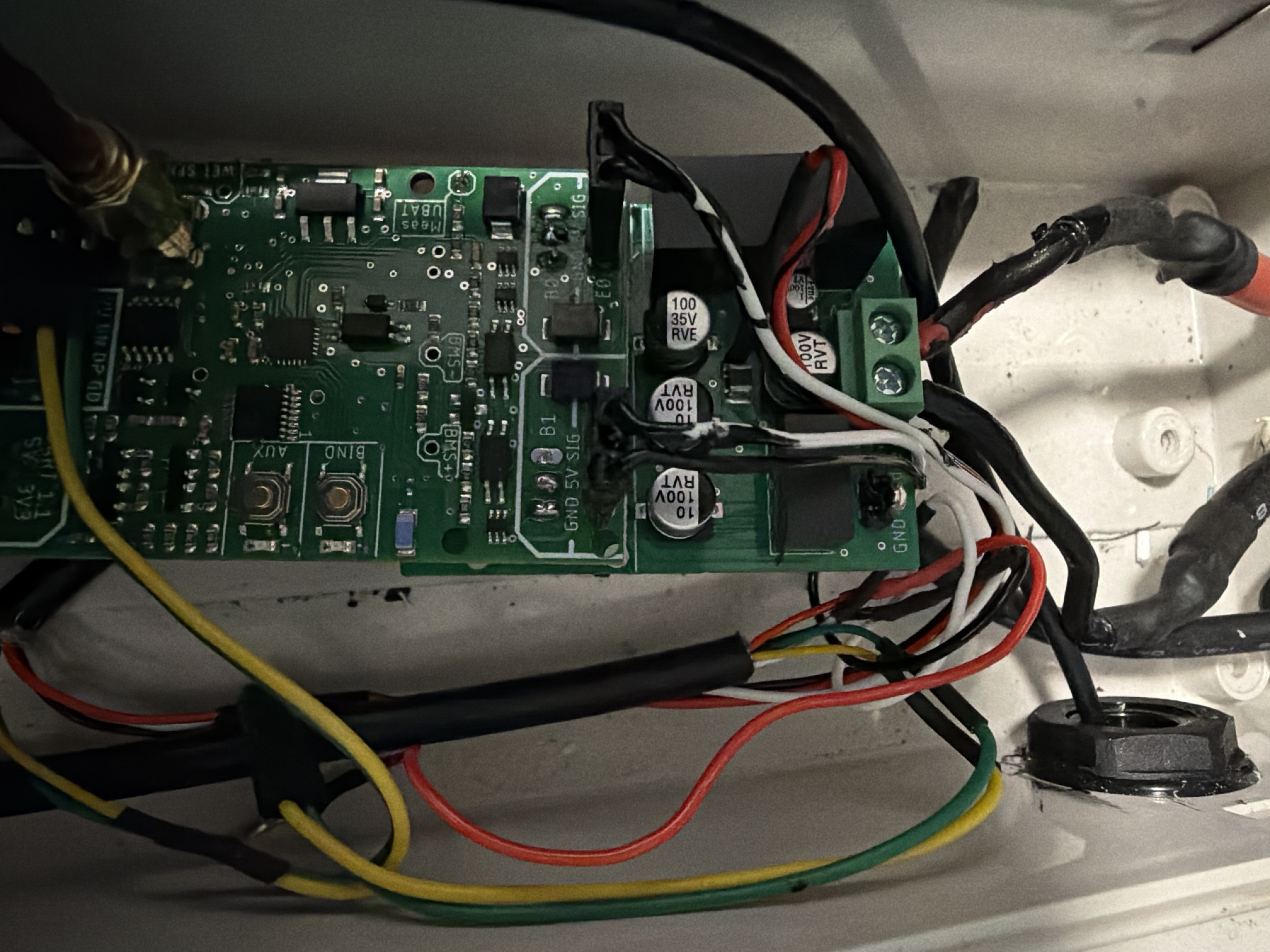
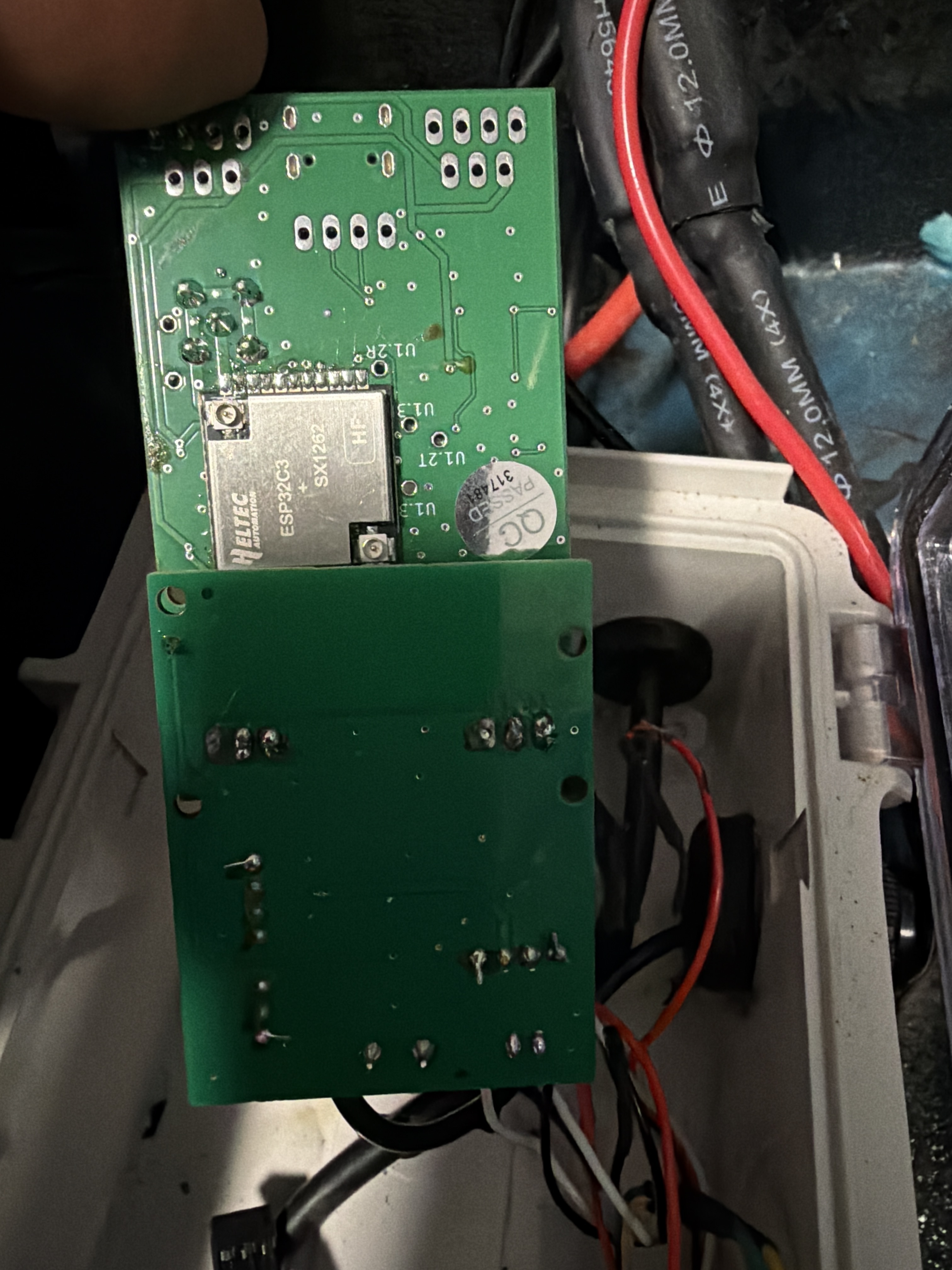
This part in picture is it possible to replace or do I need to buy another RX
Hi Ludwig,
I had a Rx that Im trying to program.
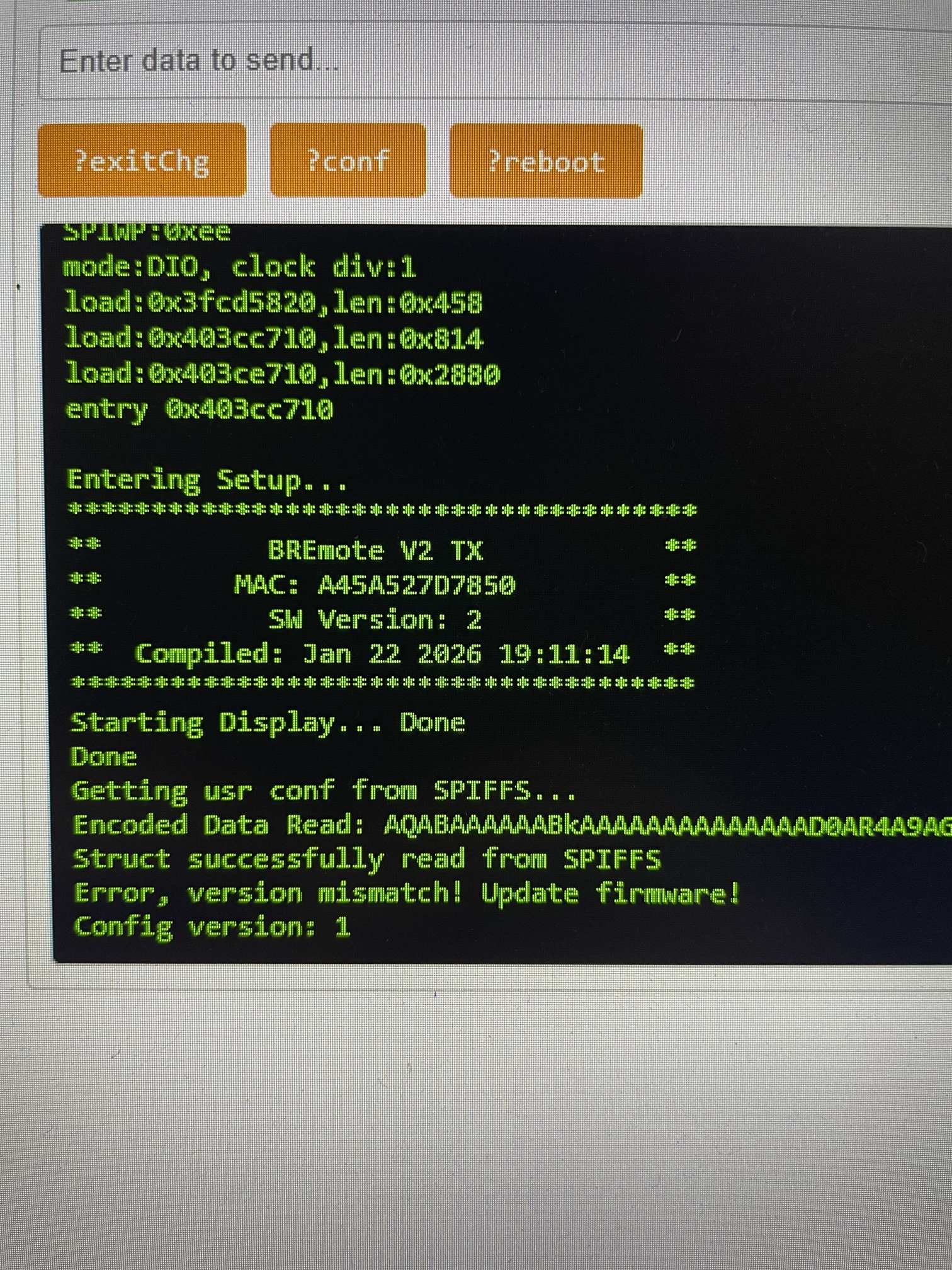
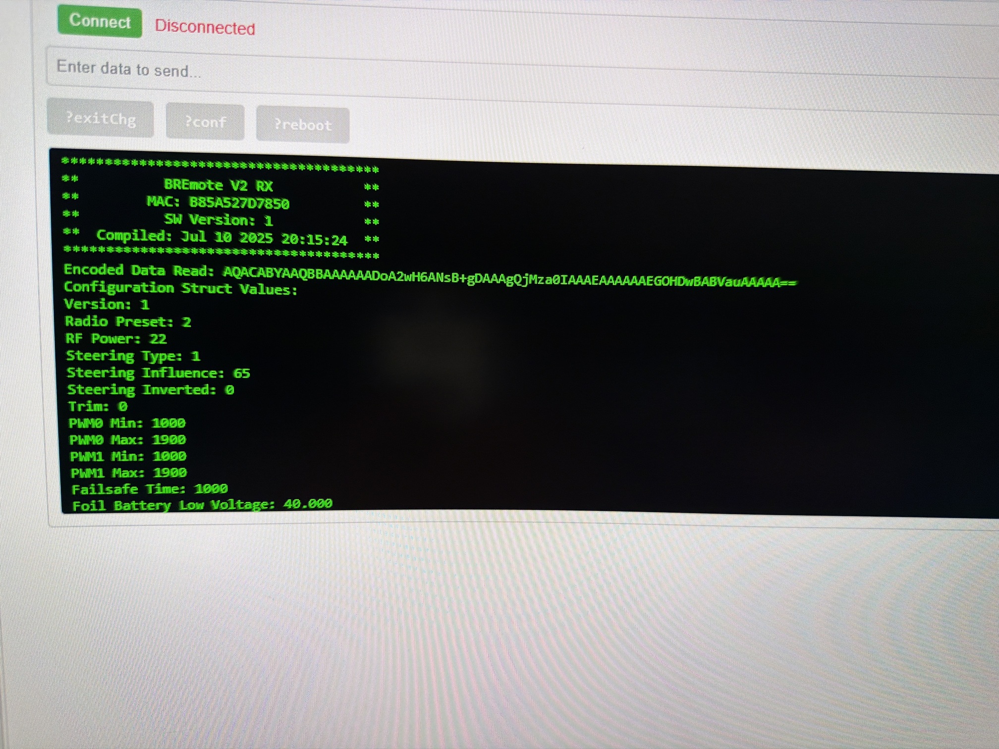
Ive tried uploading V2 .2.3 Intergration ino bin and now i have no connection with Rx with both Lights on rx on solid.
What do I need to do now?
Astan

Which part exactly blew? This can’t be from moisture, I think you have some severe failure or mistake in your circuit, like battery voltage and 5V mixed up, wrong polarity,…
Just in case you have carbon fiber close make sure nothing touches it
That and the image of your 3rd post means firmware upload was incorrect
Upload the .merged file to address 0x0 to fix that
FYI for the future: You can edit your post if you want to add information or questions, you do not need to create 3 replies.
Will the RX survive running without antenna for a while, for test purposes?
Or does it need the antenna connectod all the time to avoid damage (I know some receivers do).
I have not tried, but I think damage is likely to happen without antenna.
If space is a concern, connect a U.FL antenna to the chip directly and select a low power level of -9 or so
If you have you can also solder a 50 Ohm SMD resistor between the middle and one of the outer pins of the SMA connector
I will change my whole wiring setup I had a drop off water in one of my positive wire joints.
I also tried to download the merged file and was unavailable. I will try again when I return from work next week. After the merged file upload do I need to upload bin file again or just go through normal setup with serial port?
Thanks
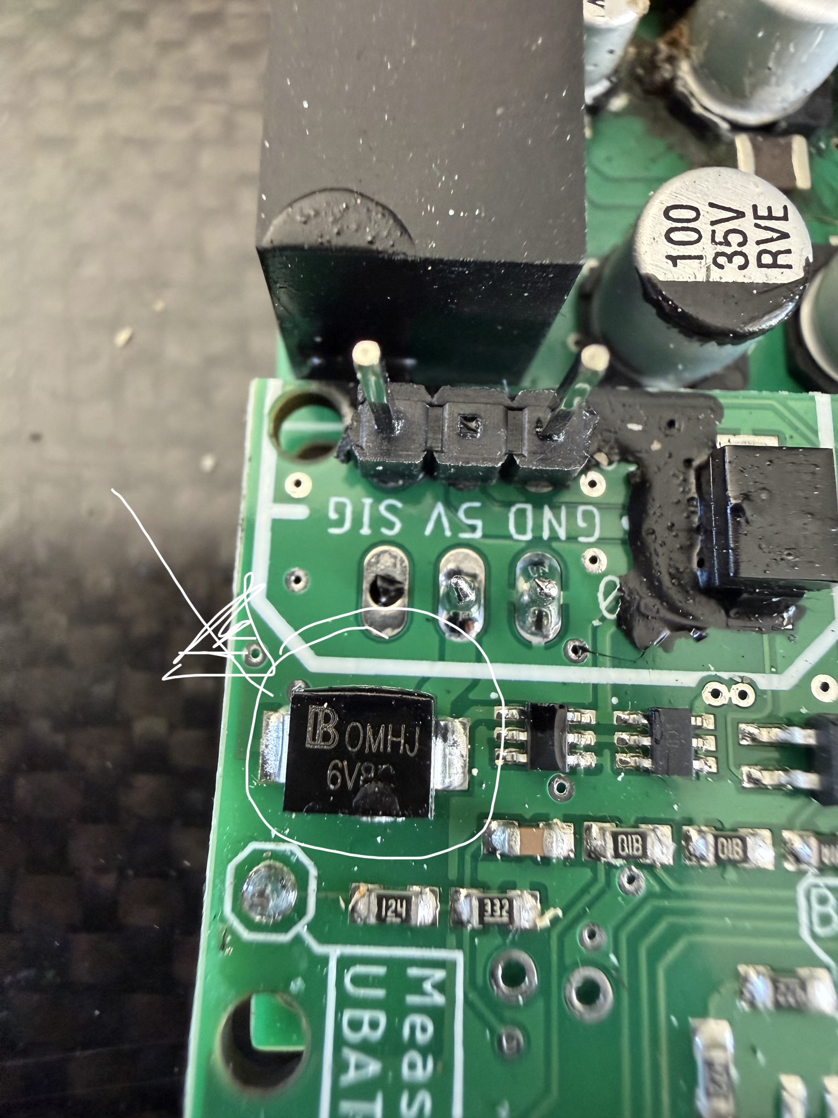
If the part in the 2nd image blew (labelled OMHJ 6V8) you either:
- Applied >6.8V to the BEC input or
- Applied negative voltage
Both at a high current if 1A or more
Again this points to a severe wiring mistake
After merged upload just proceed with serial terminal and configuration like shown in my videos
hey! anyone want to join the follow me development? that would be so nice to have some people involved and committed to it.
I burned my second RX while doing tests with 2 esc (mini vesc flipsky 6.8 and sequre 14200)
The test with the 6.8 was not conclusive even with calibration. then I changed to the sequre, a flame appeared in E0 on the 5V.
Question: the integrated BEC of the sequer outputs a voltage of 5.2 volts and 3A: is it the cause of the RX’s burnout?
I’m making another attempt, I bought a new Brememote kit with the BEC.
Question: is the connection scheme ‘BREMOTE V2-2 x ESC with BREmote BEC Board’ correct? Why connect the GND and 5V wires of the ESCs in E0 and E1 when the BEC provides the recommended current in B0 and B1?
In summary, is it possible to connect only the “SIG” wire of the ESCs in E0 and E1?
Thank you for the answers.
I have uploaded merged file and got new rx going again but can you explain why i only get one motor working as it should. The left hand motor just beeps as if its not bound but if i swap signal plugs it works fine. I had this issue first time I setup as well is it the ESC needs recalibration again? i know its something simple but just trying to get my head around it?
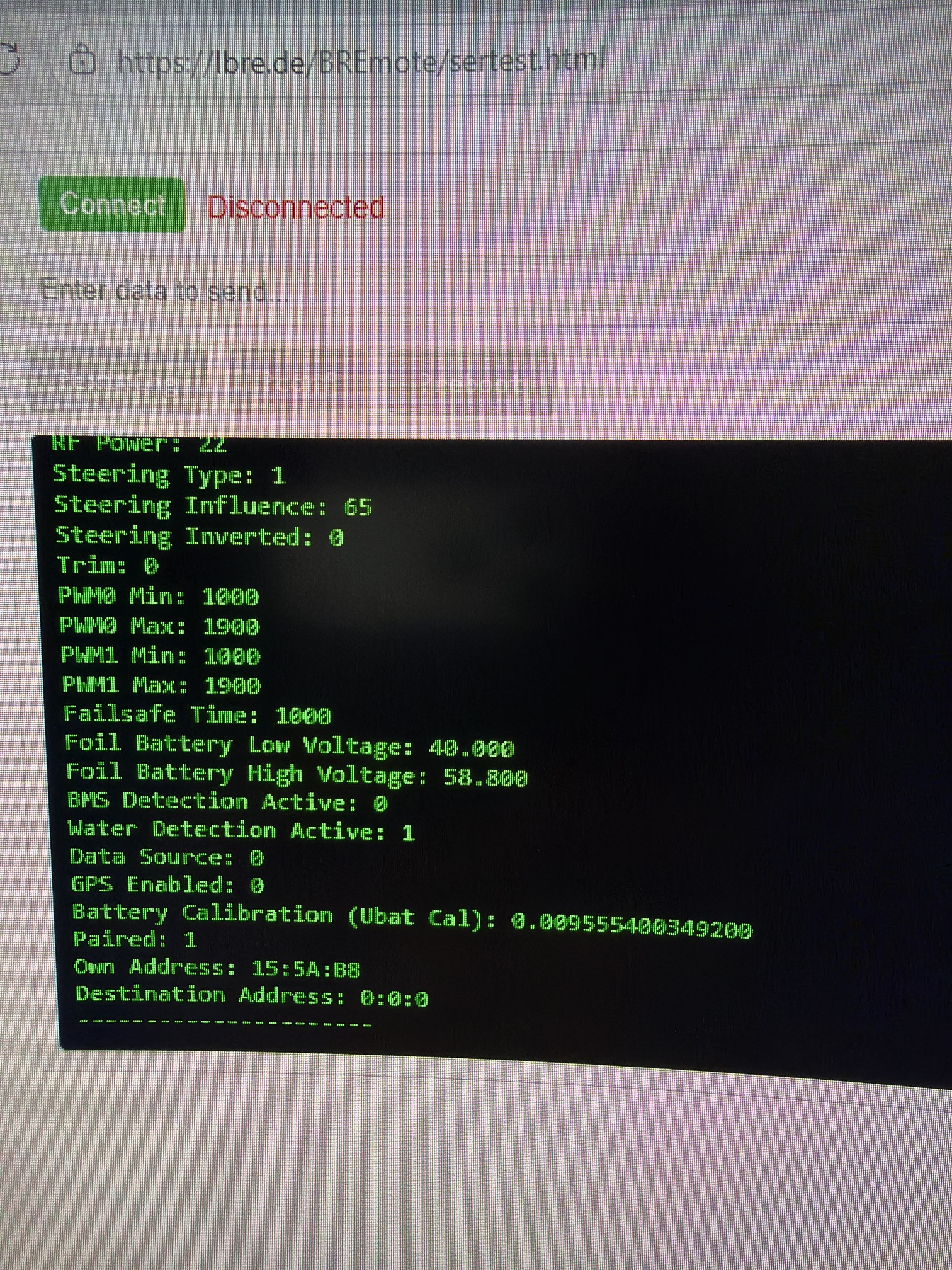
Data string is AgACABYAAQBGAAAAAADoA2wH6ANsB+gDDgAAAAEAAAAAAAAAAAAAAAAAyEEAACBBAAAgQQAAoEAAAAxCAAA0QgAANEJBjhw8AAAAAOgDAQAAABVauAAAAA==
If the ESCs have an integrated BEC, just connect them like the VESC example, so leave out any external BEC, even don’t use the BREmote BEC, only connect the ESC through the GND, 5V and Signal wire. Alternatively, if you suspect a problem with the ESCs own BEC, connect like “ESC with BREmote BEC” but leave out the 5V connection to the ESCs, so only connect GND and signal wire
Config string looks ok
If the same motor only works on one side, but the config string is ok, there might be a wiring issue. Please share a schematic how you set up the system.
Everything has been wired up the same as before and it was working fine but since uploading something has changed
I’ve checked programming of esc and it’s fine. I swapped esc signal wires to eliminate esc wires but it works ok in opposite E0 then E1 has problem I guess
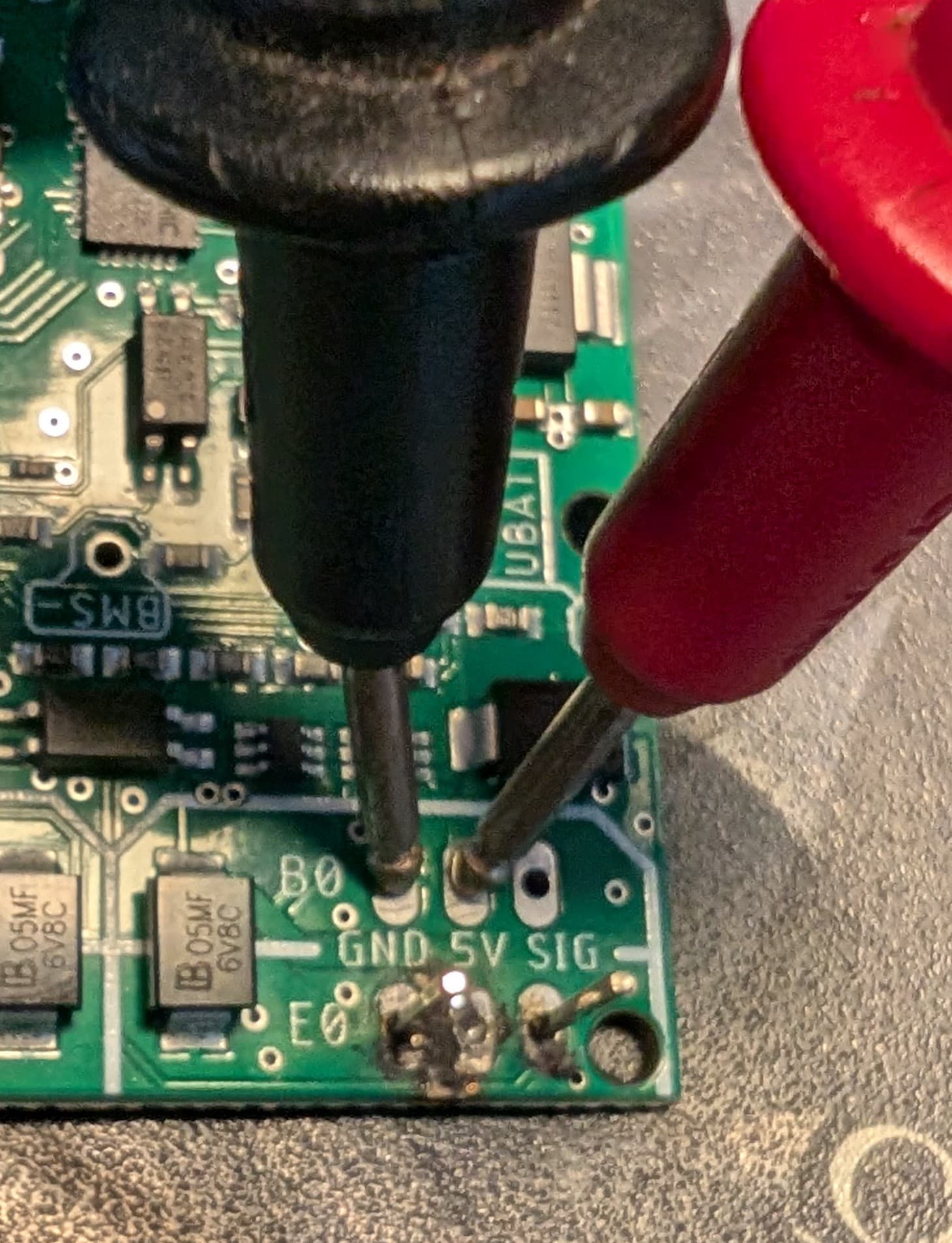
Can you verify there actually is 5V on both B0 and B1 measured to their respective GNDs?
Also you can try a ?printPWM command an see if both values are moving nicely from 1000 to 1900
If that’s all ok, try recalibrating the ESCs
Will try tomorrow thanks
Sorry noob at electronics but
With multi meter at which points do I check 5v at B0 and B1. I don’t won’t to blow myself up
Hi ludvig!
i recently finish my bi-motor to with a second hand (brand new) bremote v2…and I really enjoy it for the first 5/6 sessions…and on rhe last my tx miss the connection at the end…when i shut down and restart her the led was less flashy and write: ECH…so i think it was a corrosion on the magnet system…so i try to upgrade the firmware to fix the pb (and i also clean connections…)
But now i’m stuck on : ESV…
Was on tx v1 before and ow i’m on tx v2…
Please help ![]() there waves on the way!
there waves on the way!