The good way is to manually copy the values, there is a description further up.
Hi ludwig, I found your video about that yesterday evening…i’ll try this today! Thanks for your support , all of you…i’m not an ingeneer so I’m a bit lost even in windows…
If you want a shortcut, you can try this: BREmote Config Converter
DId that just for myself on a sideproject, but it (probably) should work.
Just stick to Base64 and V1/V2 and check the values after.
That is left side set to TX,V1,Base64 and enter your old code.
Right side set to TX,V2,Base64, click convert.
I spend my day to try to understand something…i had lots of issues with my usb port on the remote…but i tried to do what you explain in video…and no more connection with the remote…so i try to downgrade my tx to v1…so connection restarts…and i may fix something so i try to upgrade to v2, and no more issues…then i try to make the job on my rx but my computer never see him, even i can put power on it to pair my remote back…in doubt i plug every thing on and my tow is now ready to ride…with txV2 and rxV1…not shure its legal in vatican, but i gonna try tomorrow !
Try another USB cable
Some only can charge and not transmit data
Hi,
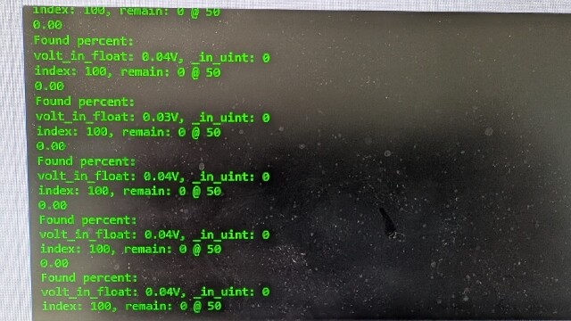
I have this message constantly scrolling by connecting my RX V2 to the serial terminal.
I just received this Rx, I have already modified some values via the serial terminal without problems but today, I have this message.
thank you for the response.
Did you by any chance send a ? printBat
Send a “quit” or just power off and on the Rx
No, I did not send “? printBat”
I specify that the Rx is connected to the USB port of my computer.
I tried several cables.
I tried «quit» and turn off the RX but without effects.
The different ‘? conf’ ‘? exitchg’ ‘reboot’ commands work but the screen continues to scroll.
Ok
Maybe I left some debug command in by accident
If it annoys you downgrade Rx to 1 version before
It’s a bit boring, yes and no.
It’s difficult to read the data because the screen scrolls all the time
If it does not affect the operation of the RX, I can leave as is.
But I still can’t get an operation with my esc and my engine.
With the order “? printPWM”, I see the values change between 1000 and 2000 with the accelerator and the direction but no signal seems to come out of B0; I tried with a servo like in the video “bremote V2 build log#3” but no movement…
Please keep in mind for servo you also need to apply 5V to B0, connect the servo to E0
I thought that the power from the USB plug would supply the 5v of the E0.
So, if I power the 5v of the B0 (with the B.EC.), I would have 5v in E0?
I admit that I do not understand well the functioning of the different plug B0/E0 and B1/E1.
For ordinary users, would it be possible to have a small video explaining the interactions between these elements, this could avoid damaging the RX (2 burned with a 5.2 V power supply)
Thank you very much.
It is explained a bit in the schematic
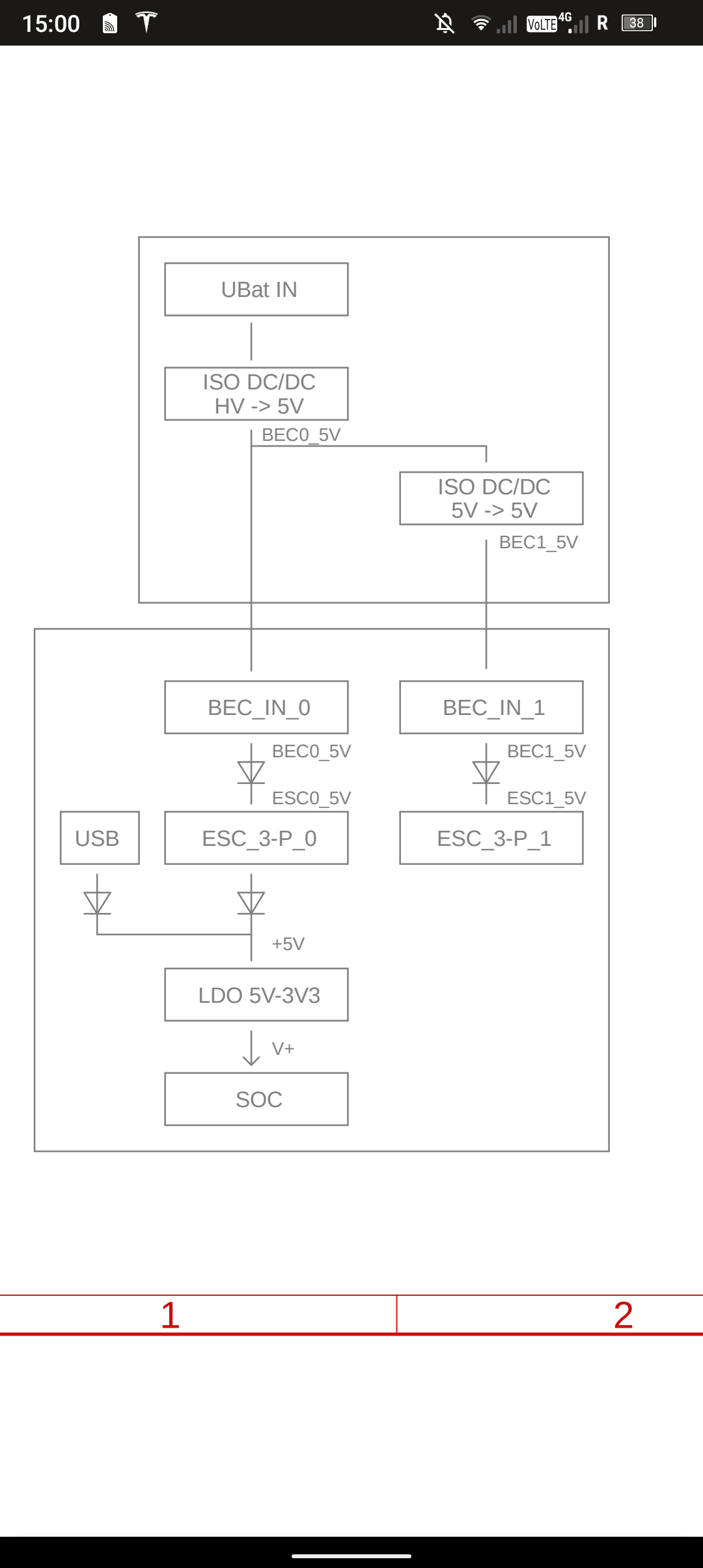
The arrow like symbol is a diode, it will only let electricity through in the arrow direction
As you can see, USB can supply power to the processor, also E0 and B0 can do that, but never back
The idea is:
If the ESC already makes 5V itself (e.g. all VESC) you connect it to E0 and it will power everything
If the ESC does not do that, you also need a BEC that inputs power in B0 and that power is internally forwarded to E0 and the processor
For the B1 and E1 it is the same, it has some isolated electronics that also need an independent power supply.
1 Like
ok for the supply of the servo in B0 and not through the usb port; I understood.
On the other hand, the ESC has battery power so, in principle, we can only connect the black (GND) and white (SIG) wires to port E0 and power the RX via USB; should that work? (tricky question, it doesn’t work with me)
NB: I’m afraid of powering the RX with a source other than USB because I have already burned 2 RX, it’s silly, I know, I won’t take my PC on my tow boogie…
In any case, thank you for the pedagogy
This will only work for E0, not E1
Hello,
This morning, I decided to power the Rx with the BEC.
As a precaution, I measured the output voltage of the BEC, result, 5v on B0 and 5.43 V on B1.
(GND bridge closed)
Is it normal to have 5.43 V in B1, is there a risk of overvoltage for the RX?
Yes that is normal and within the usual limit of +/- 10%
Hello Ludwig,
This means that the short circuits on my first 2 RX are not due to the 5.2 volts of my ESC instead of 5 Volts: correct?
I think it’s the welds of the headers that are causing the problem.
The aspects of the welds are good and there are no weld bridges (checked with a multi-meter).
I noticed short circuits (sparks and fumes) on my first 2 RX and on the BEC.
I am therefore thinking of overheating during welding.
Can this explain the short circuits and the lack of signal sent to the ESC?
Thank you
Not really
Damage this big can only be with voltage that is way too high or incorrect polarity somewhere