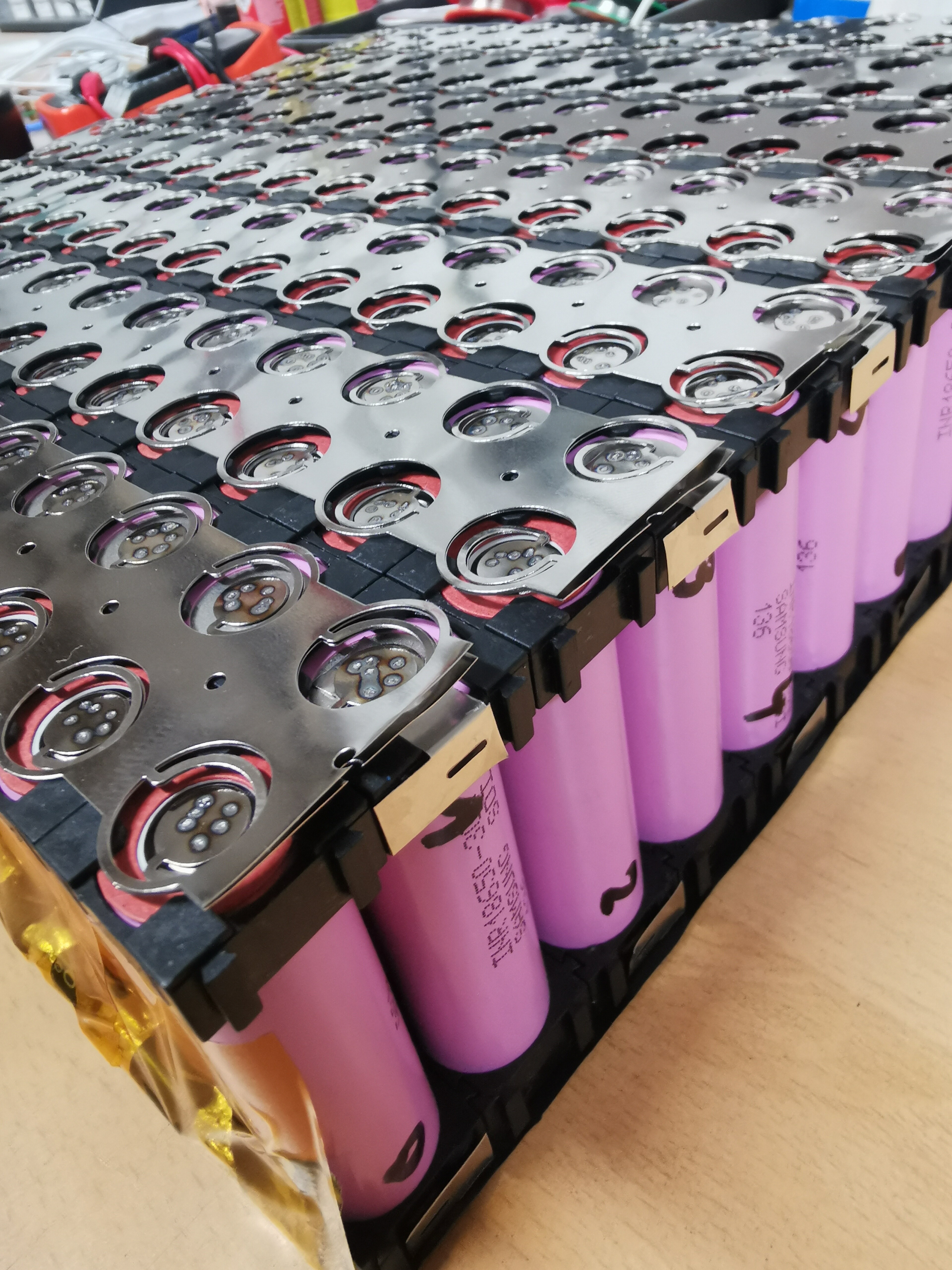
I’m about to start my battery build with samsung 50e 21700 cells. I chose to use a spot welder for the sake of time, i am planing on not fusing my cells but i will definitely fuse the main bus bar wires.
do you think i’m fine not fusing each cell? i really like the idea of using the fused nickel strip that patrickgrem showed, but there meant for 18650’s.
Yea. You’ll be fine. Individual cell fusing is a small niche market. None of the manufacturers make batteries this way because it’s too labor extensive. Well, except for Tesla. All their car batteries are individually fused on each cell.
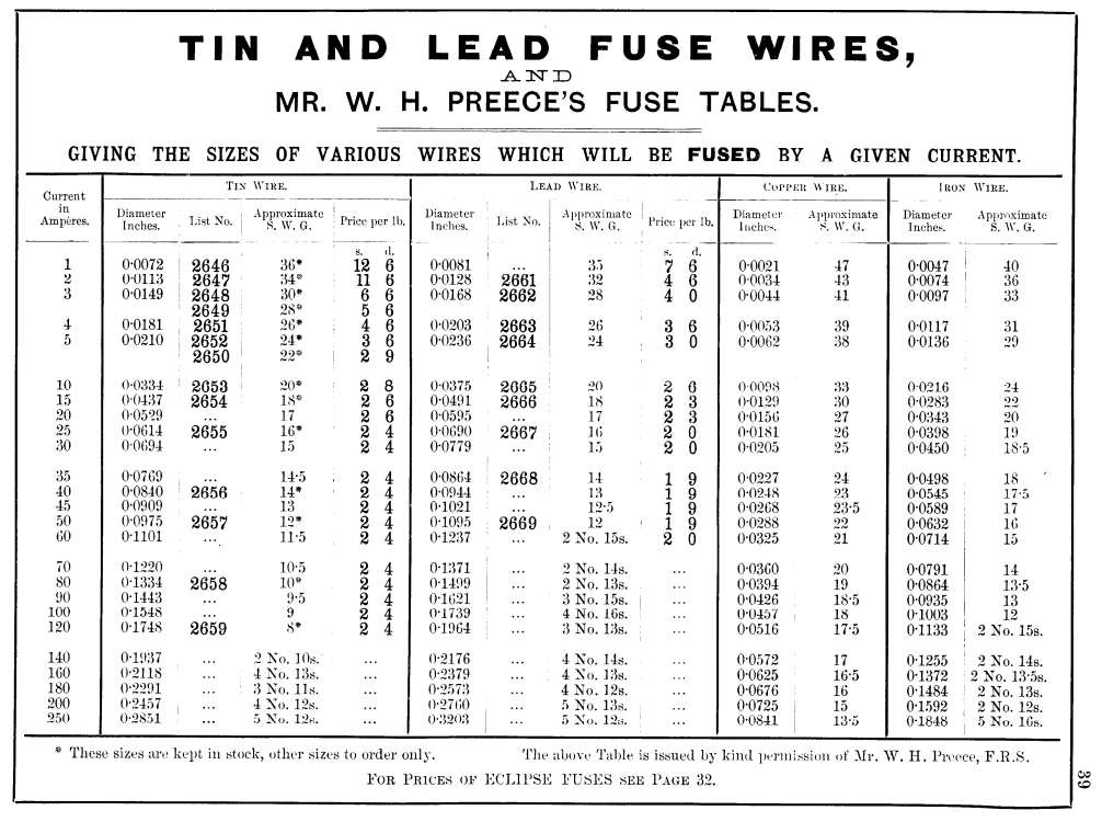
The cost of the venerable 30Q has really gone up, and to keep the battery pack affordable 21700 seems like the way to go. For this reason, we need to be able to recalculate the fuse wire size (Unfortunately not everyone has your testing set-up). So far I have found 3 interesting links on the web:
Once you realize that SWG is an old standard from the UK, and we use AWG and focus on the area of the wire instead, the data from all 3 sources seems to match closely. All seem to derive their information from Preece’s Law:
The fusing current in Preece’s law is where the heat input from resistance equals the heat loss from radiation or convection.
The discrepancy is with your testing (which I don’t doubt, the video was quite informative.) Where the tables say that melting should be expected at around 10A for the 30AWG copper cable, you found that this would happen at 25A in practice. So the fusing current from the table should be seen as the max current that the wire can carry safely without melting (my interpretation).This seems to be consistent with your observations that the wire will stay cool until around 10A, start to warm up at 15A and melts at 25A. Please let me know if you have other experience or advice interpreting these tables.
Also, while the 30AWG fuse wire seems to be a good fit for your application, I still get a significant voltage drop:
With 0.5 inch per fuse, and 2 fuses on each size of the battery I get a total of 0.5214=14 inch of 30AWG wire.
When using 150A as the battery load (from your thread), and 14P you get around 10.7 A per 30AWG wire.
For 30AWG copper wire @ 35C I get a resistance 0.3580265748 Ohm/meter
(add 4% to 109.127 Ohm/1000 ft for imperial)
Using V=IR I get a voltage drop of 1.36V. For a 58V battery that is 2.35%
I know you are trying to get the voltage drop of the entire system to below 3% but that means there is less than a percent left for the remaining components. I know you used 20AWG on the first and last row, but would it make sense to use 20 AWG on one side of each of the the batteries, and the 30AWG on the other side? This way you reduce fuse wire length by 50% and the voltage drop from the fuse wire is reduced to 1.2% and you would still have the same built in safety fuse for each battery. If my calcs are right, replacing 50% of the fuse wire with non fuse wire has a bigger impact on overall voltage drop than running 6AWG instead of 8 AWG in the mast. As always, thanks for your insights and awesome shares!
Wow. That is quite the post. I’ll have to digest that for awhile!
After a quick skim, things I can comment on…
Just doing the fuse wire on one side of the battery is a good idea.
The wire gauge chart is probably not accurate for such a short run of only 1/2".
The length of the 30AWG wire does not add up to being that long. The reason is because the cells are individually connected to the bus bars and the bus bars are connected together. So, it’s just the 1/2" top, plus 1/2" bottom. So, 1" total 30AWG, even when combined and looking at the whole pack.
It’s been over a year since I designed this. I’ll have to look at your post closer and think back to my design to comment further.
I also considered just doing the fuse wire on one side of the battery. I’ll probably due that on future builds.
Thanks for the indepth discussion! I look forward to seeing your battery build.
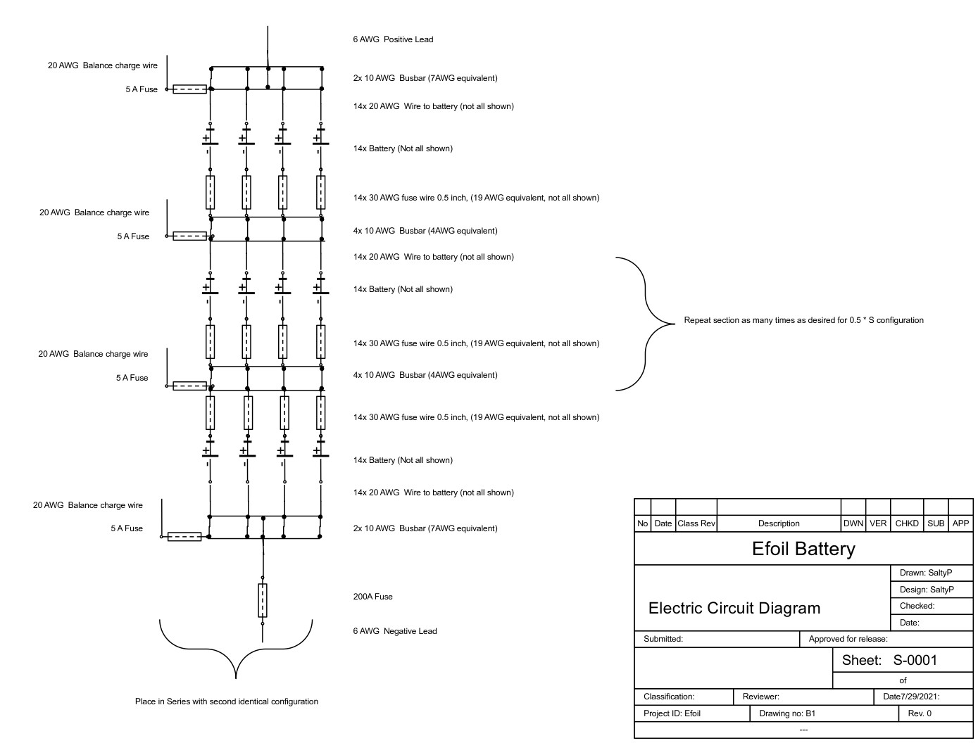
I don’t quite understand the comment “the bus bars are connected together”. Could you confirm the electrical circuit below (with the exception of the 20AWG connection wire to replace every other section) is how you have wired the battery (from the 2nd build on)? Many thanks.
I’ve just finished building an 18650 Samsung 30Q pack with these nickel strips.
I had to spot weld two layers of nickel strips, since one layer will only do 3A continuous without getting warm and will blow fast at 8A per cell.
Now with two layers I have 6A continuous and 16A fusing. Times 14 cells this is 84A and 224A max.
I’m running the pack with a 200A Smart BMS…
SaltyPaws - your calculations are interesting, with 1.36V drop in a 58V pack at 150A (with 14 parallel cells). It makes sense that the battery will voltage sag with an inch of fuse wire on every cell, totaling 30cm of high resistance wiring across the pack. All the other wires in our setups are chunky gauge to minimize losses and allow current to flow.
Runtime is precious, which is why I went for wide and reasonably thick nickel between my cells in a 6p pack, so as to avoid wasting power into heat. The losses would be much worse than 1.36V if I used similar gauge cell level fusing with 6p while pushing 150A.
I guess if you did have an individual cell fail with a short circuit, then a fused serial connection would prevent shorting the entire parallel row - but hopefully that won’t happen if we’re using good cells. It seems more likely that the balancing wires short onto each other, or a connector/plug shorts out - which can be mitigated with careful construction and a pico fuse where it the balance wire joins the cells
I can imagine some ways an individual cell could fail would include:
-salt water in the battery pack
-a piece of stray solder on the positive terminal
-a jagged square corner of nickel bridging the positive terminal to the outer can
Good quality +ve terminal insulators seem essential, and full battery waterproofing. I’m not sure I would trust a shrink wrapped pack which is only separated from the ocean with a single waterproof case.
Yes. That looks correct. The voltage drop of my pack is super low. I did a bunch of testing when I first built it a year or so ago. I’ve set my VESC amp limit to 250A and Towed foil boarders into the surf. No voltage drop issues.
I think fuse wire on just one side of the cells is a good idea. Nice improvement over my first gen of these packs.
For an 12s 10p, what price should I expect? I am a bit lost with the 18650, the 18650 30q are maybe on the limit with their 20a discharge on 10p pack… But they are already expensive (18$ here and 10$ on Bangggood)
If I built it would be 2x 6s 10p and I use my RC hobby charger.
A really nice battery case, with nice inner dimensions to accommodate a 14s14p setup : 342 x 342 x H79.8 (70.8 + 20 - 5 - 6)
How much is it sold (no visible price) ?
IP 66 protection: did/will you do sthg to improve that a bit ?
Yeah, I’ve done quite some research to find a case that would both accommodate a 14S14P Setup or more and fits in the cavity…
The actual price is around 200€, I haven’t done any additional waterproofing. But I’ve submerged the finished case without battery for 30 mins under 50cm water and no drop inside!
For the next box, consider asking your buddy with the CNC to machine an Isogrid in the 1/2" acrylic to remove a lot of weight at little cost of strength.