Challenge to myself - Fully 3D printed pumping board, no fiberglass or carbon layup

Hello all,
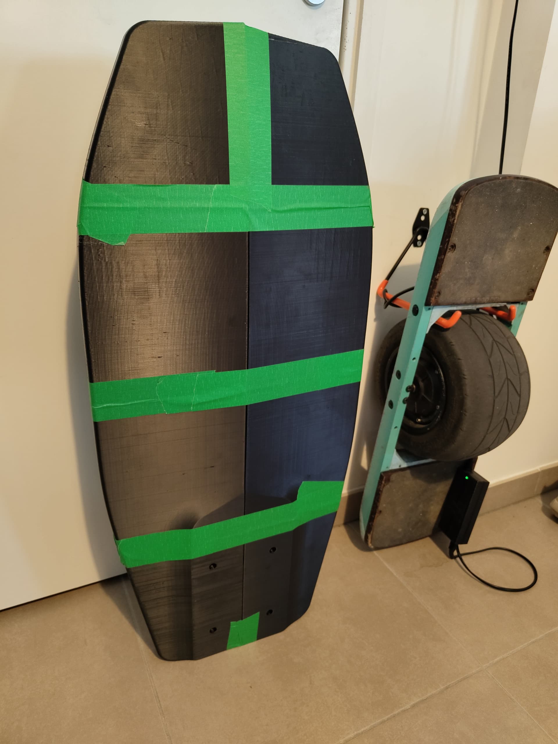
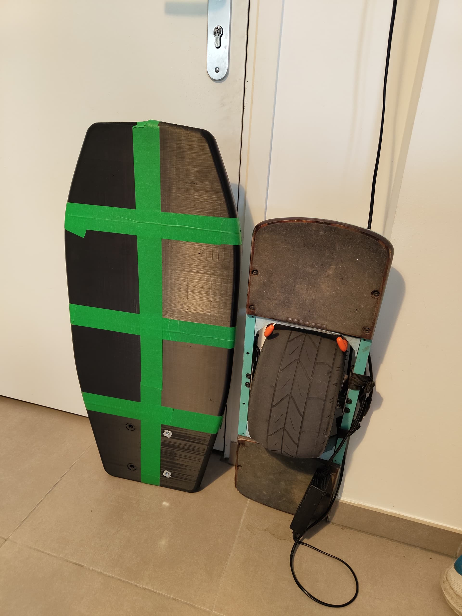
I have been thinking and working a little on a project, to make a fully 3D printed foil pumping board.
nowdays you can buy purpose perfect boards for 400, so why bother?

I am always looking for engineering challenges and I like 3d printing.

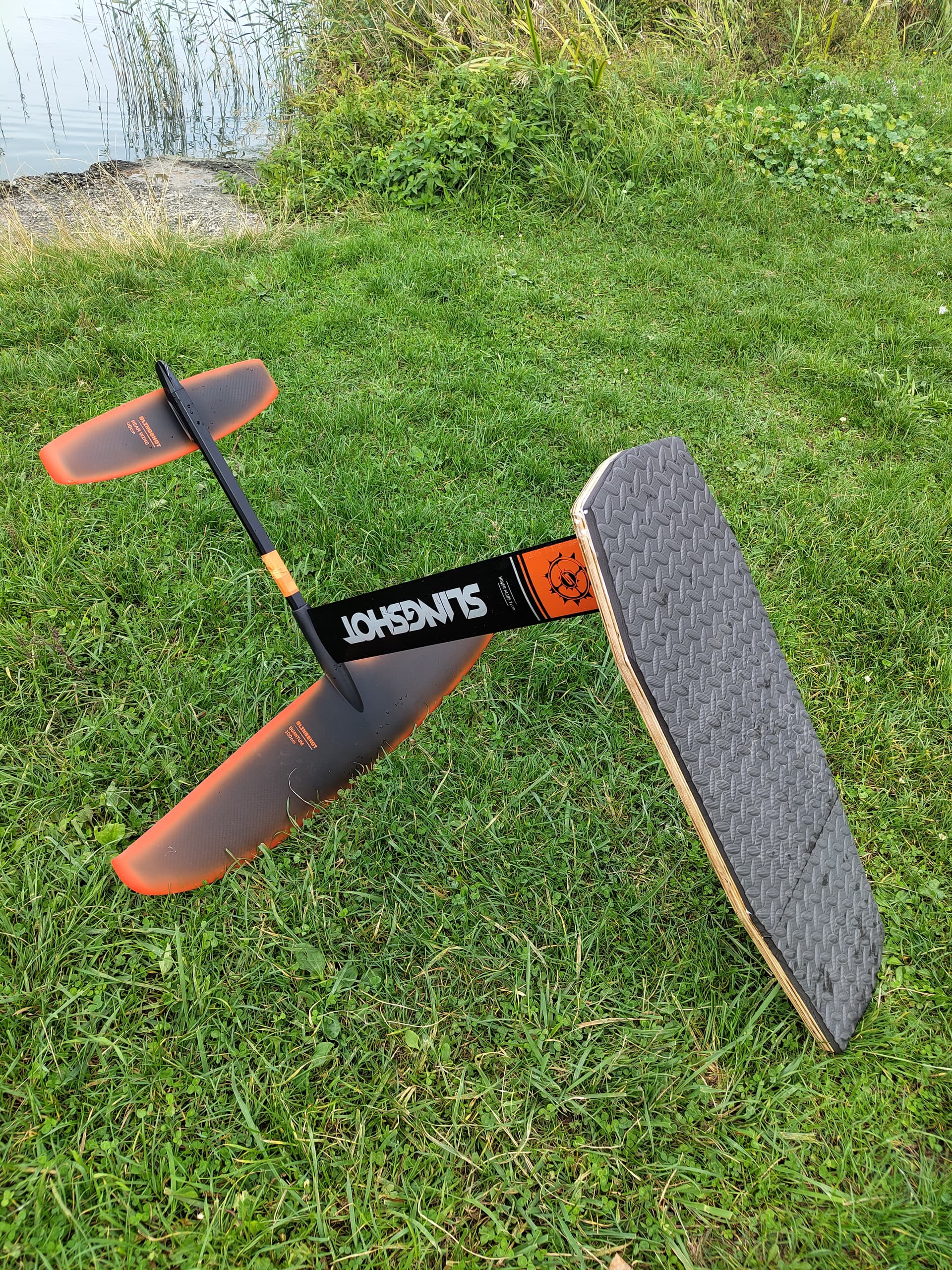
I now on the V3 of my efoil assist with 7s4p 21700 and 6374 and 6384. My goal with this system was to ease my pump foil journey, but now i’m a little stuck on that front. so I got a new better foil, a 25l surf foil, and that should spice the pumping and faux drive game.

in the meantime my local scene is more about pumping, and I’m about engineering, so why not spend hours and money on another DIY pumping board.

I have seen a very nice article about a printed core and glass/carbon layup board here :

Also, some guys in france are puming with a set-up consisting of two carbon tubes and a thin platform+bags for buoyancy.

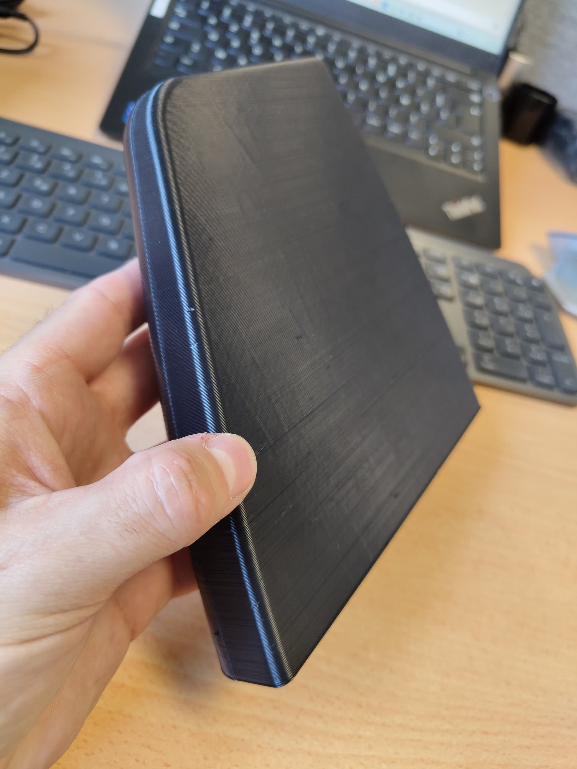
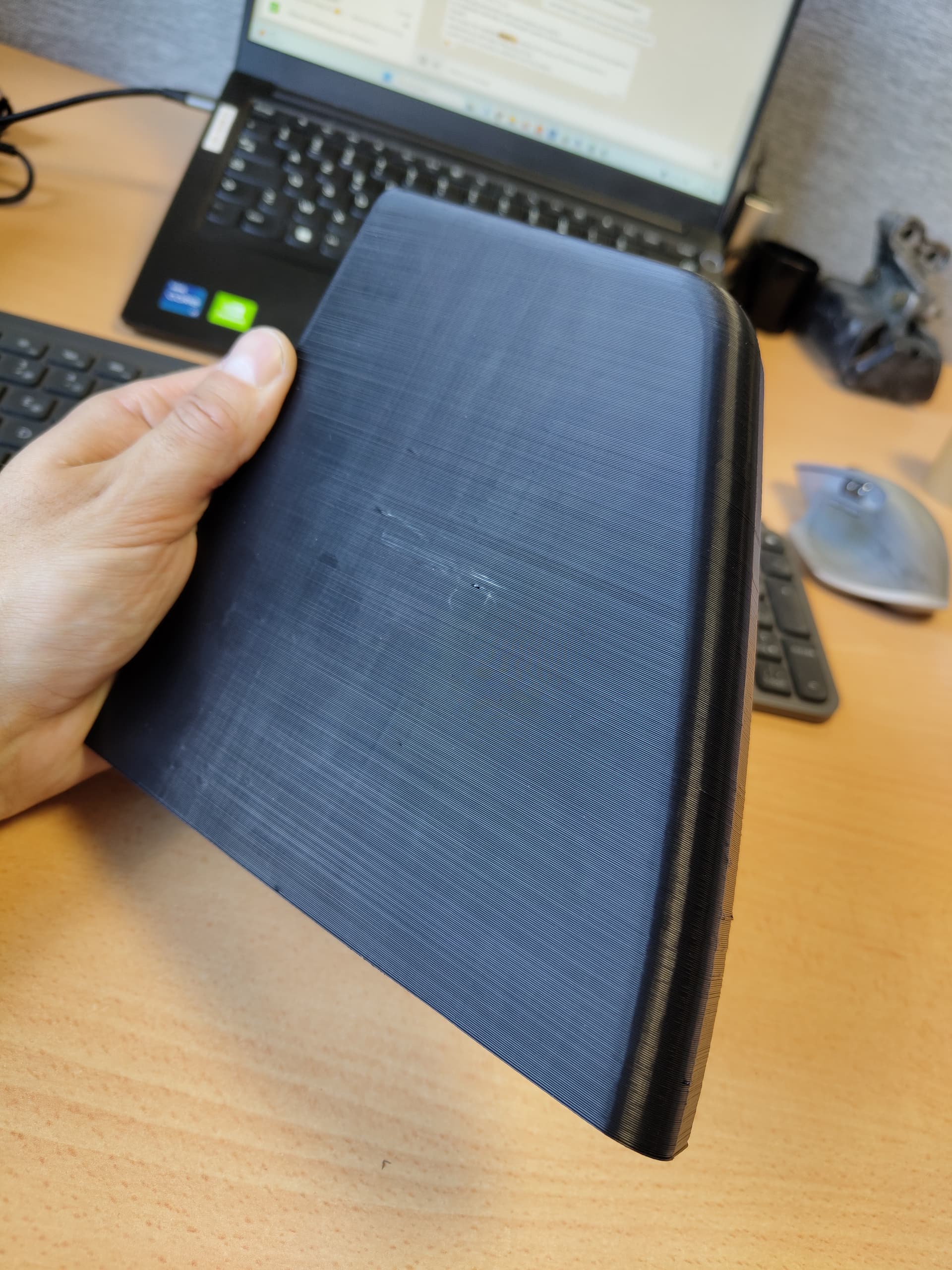
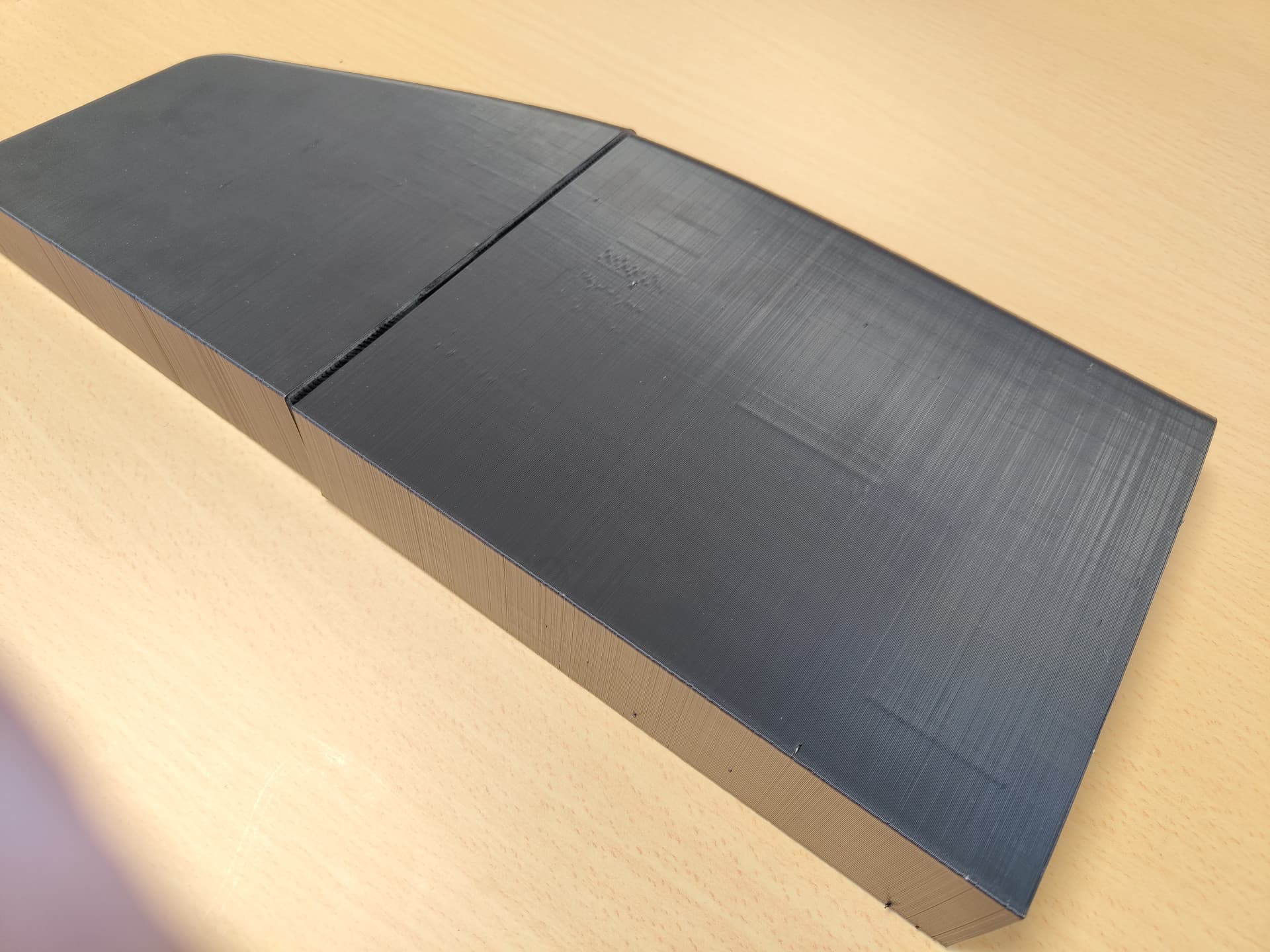
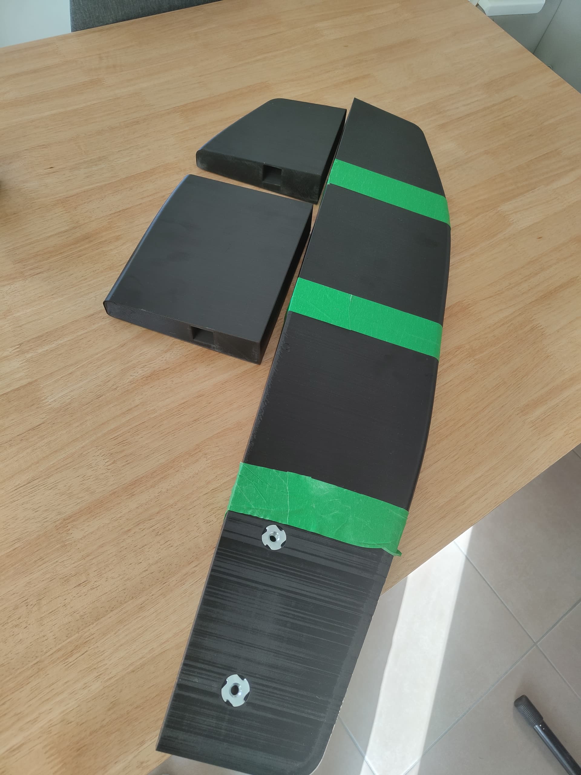
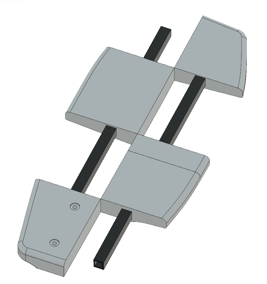
My goal with this project is to make it replicable by any hobbyist with a printer and good printing abilities in the world. Most machines are capable of 220mmx220mm, so I set my blocks at 215mm each. By 8 blocks we can make a pumping board.

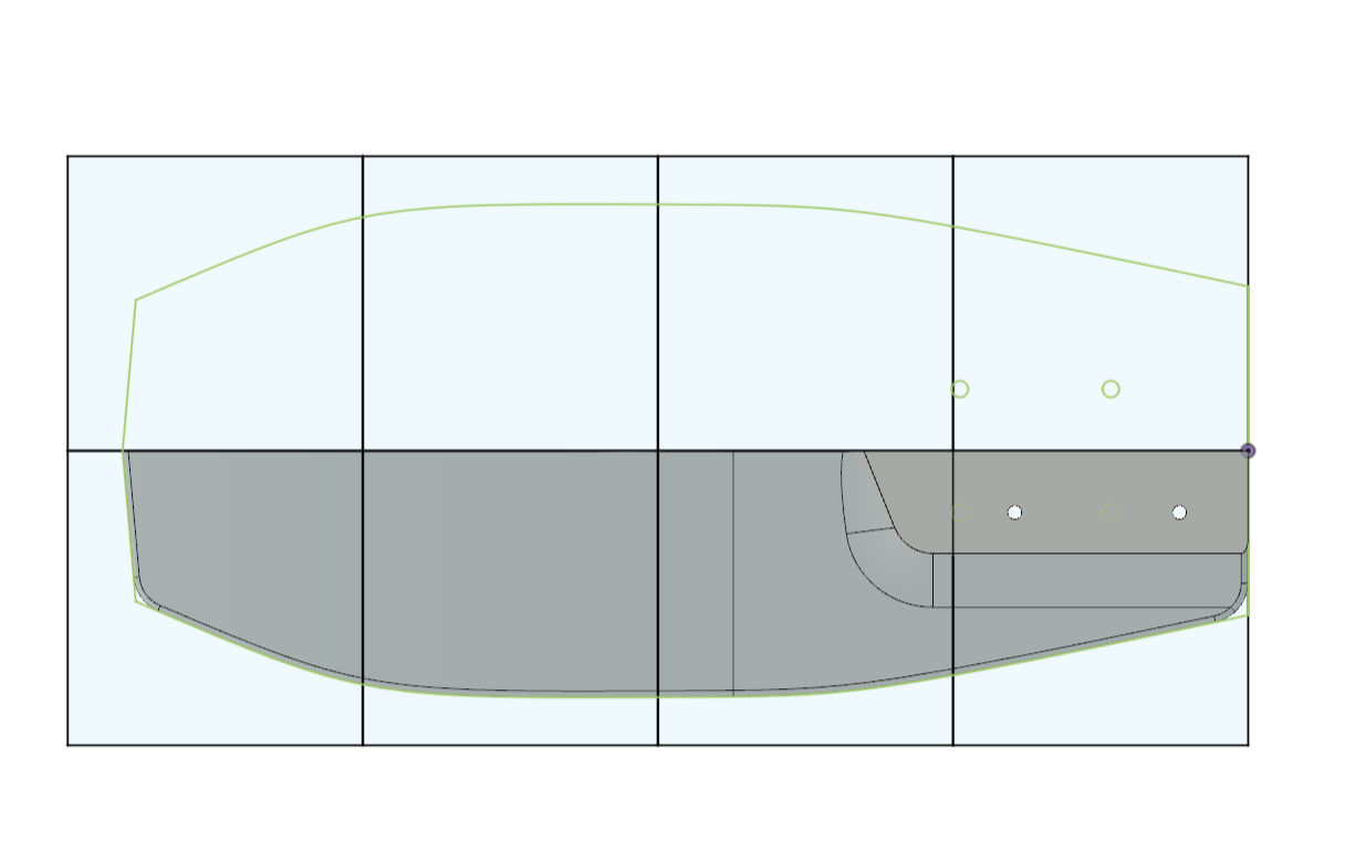
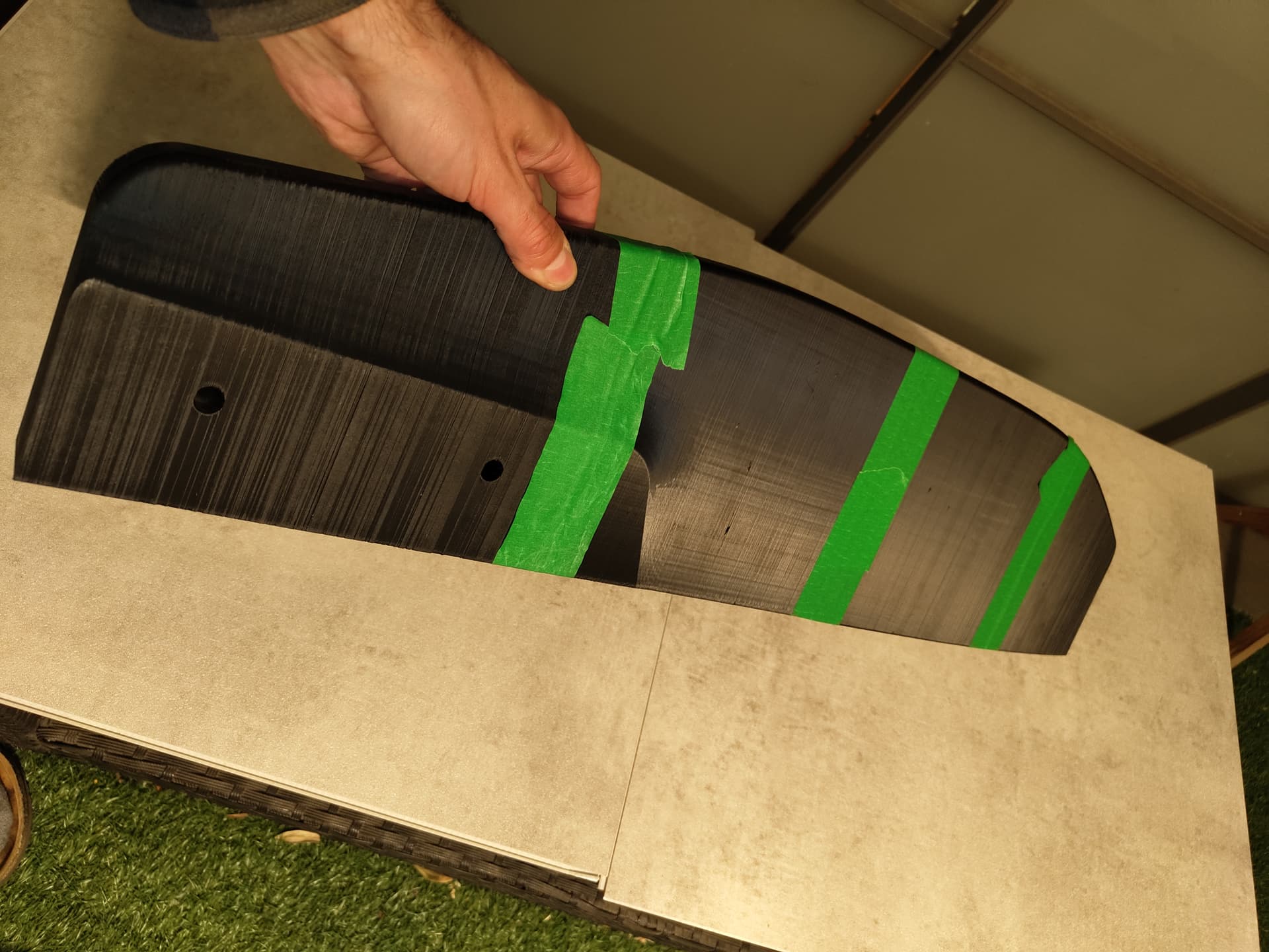
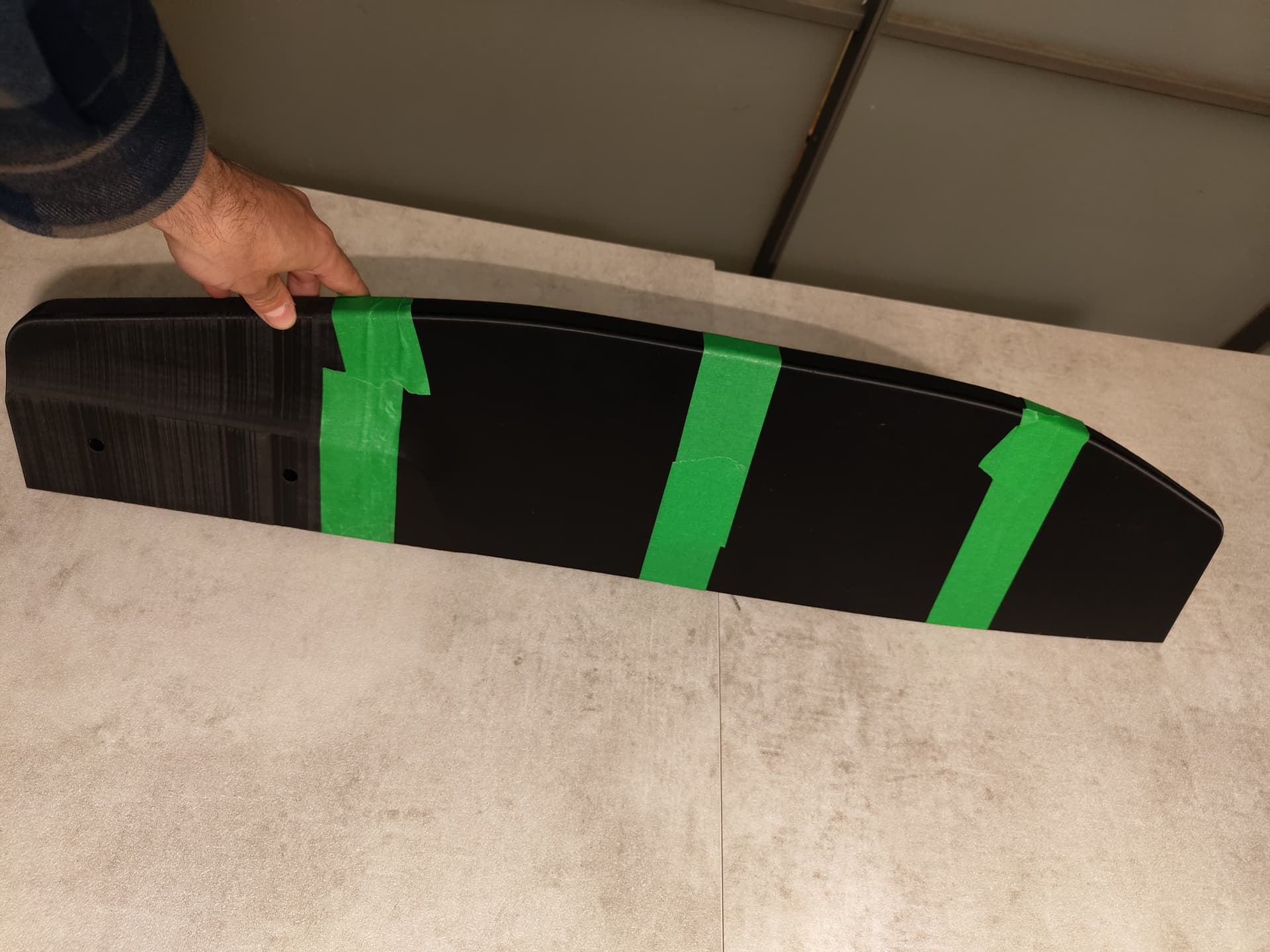
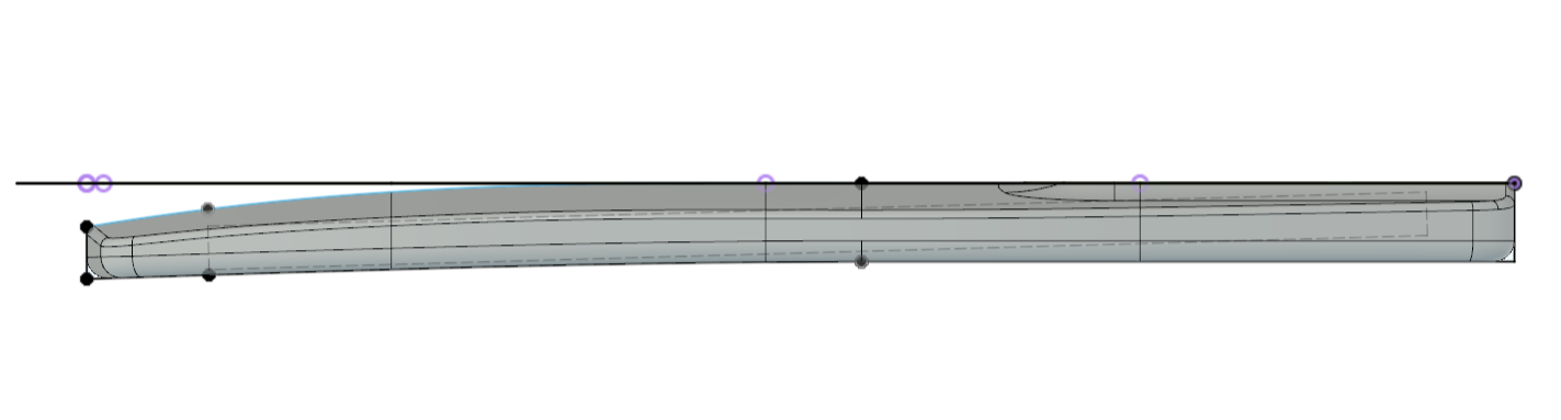
Then some rocker, fitting a angled 700x25x25mm square tube :

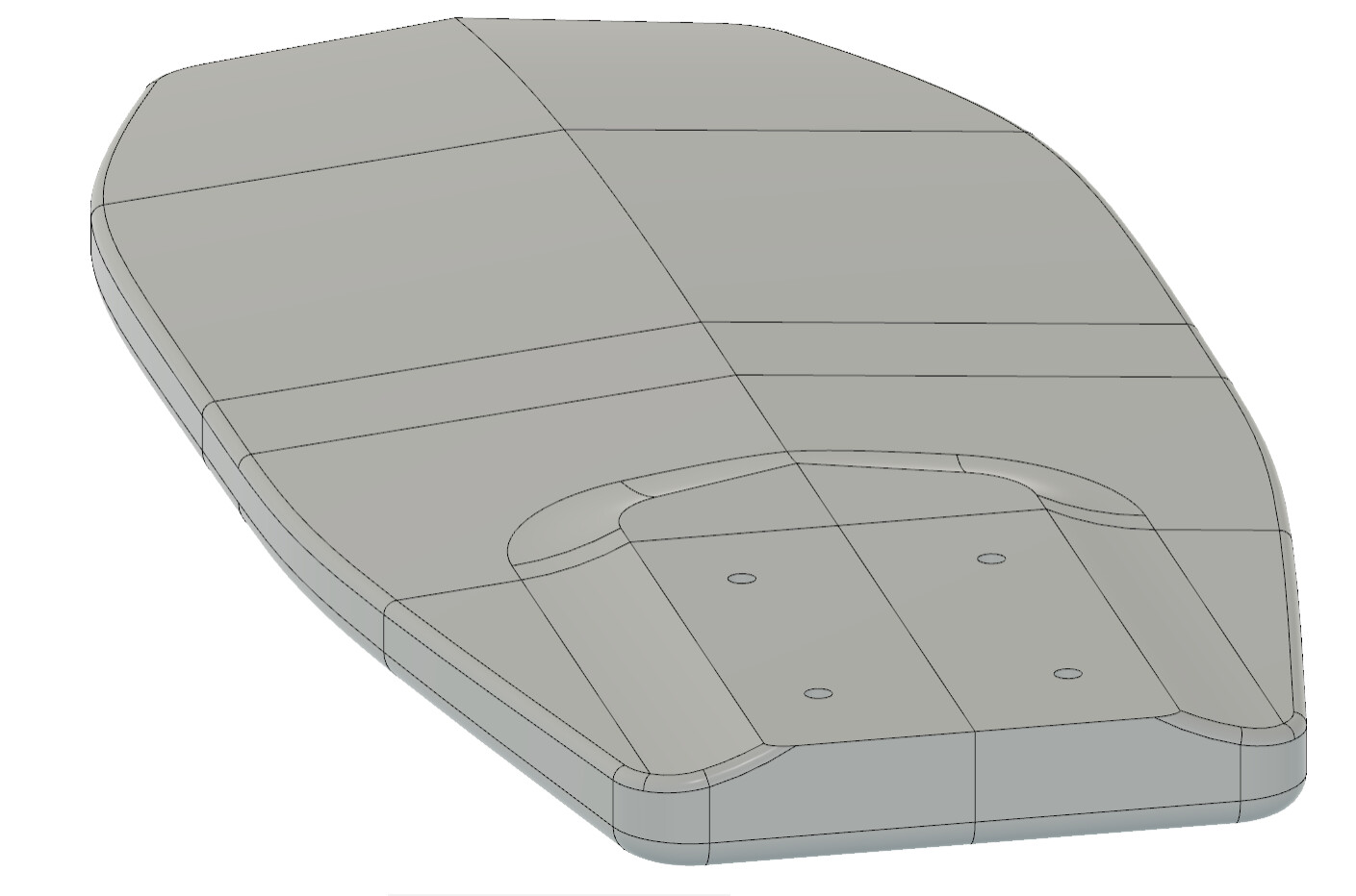
some shape for the underside :

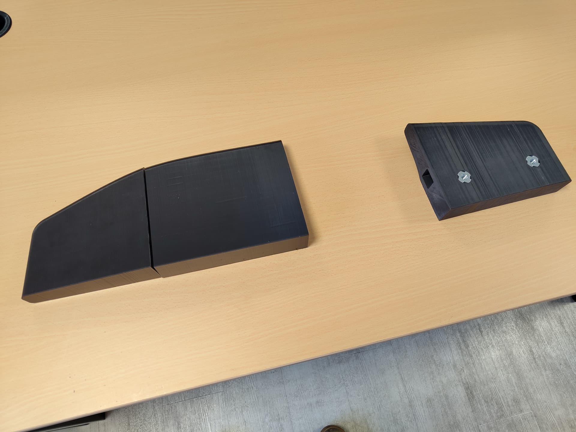
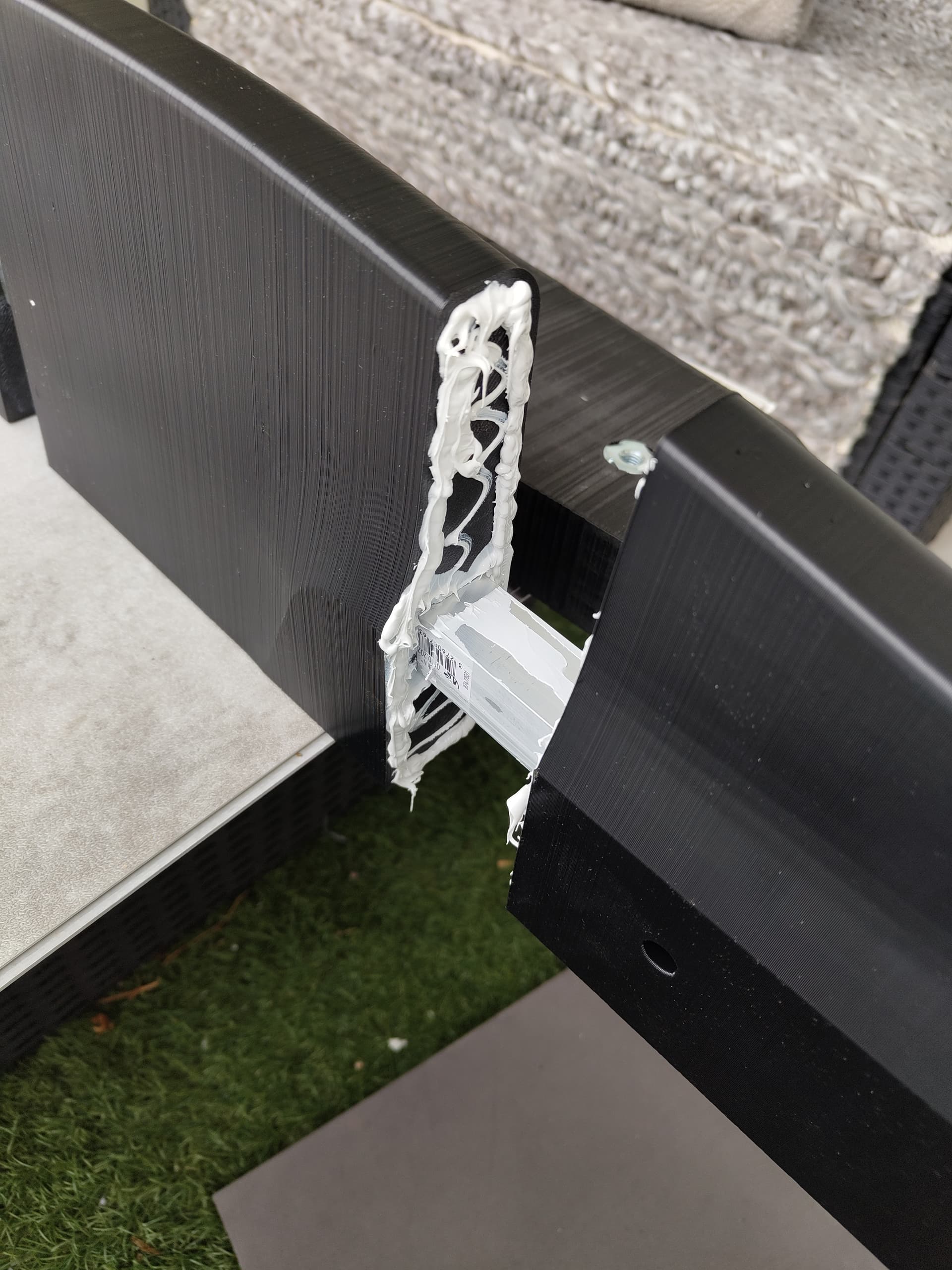
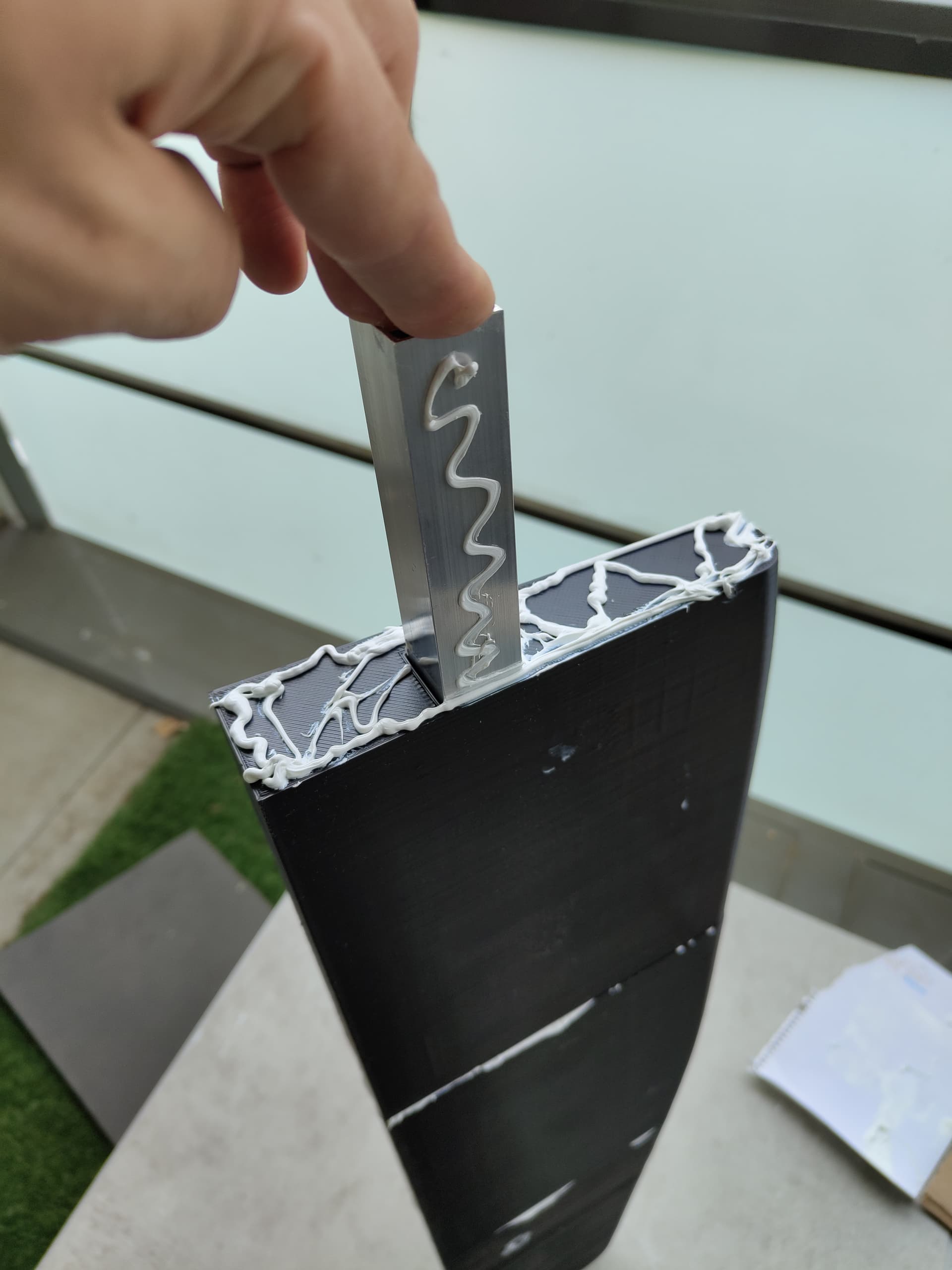
So I was thinking about carbon tubes for main rigidity and positioning the different blocs.

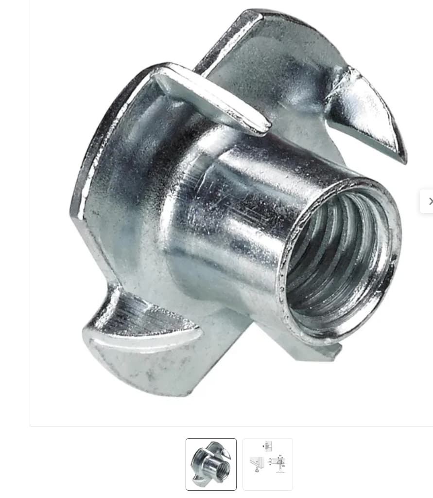
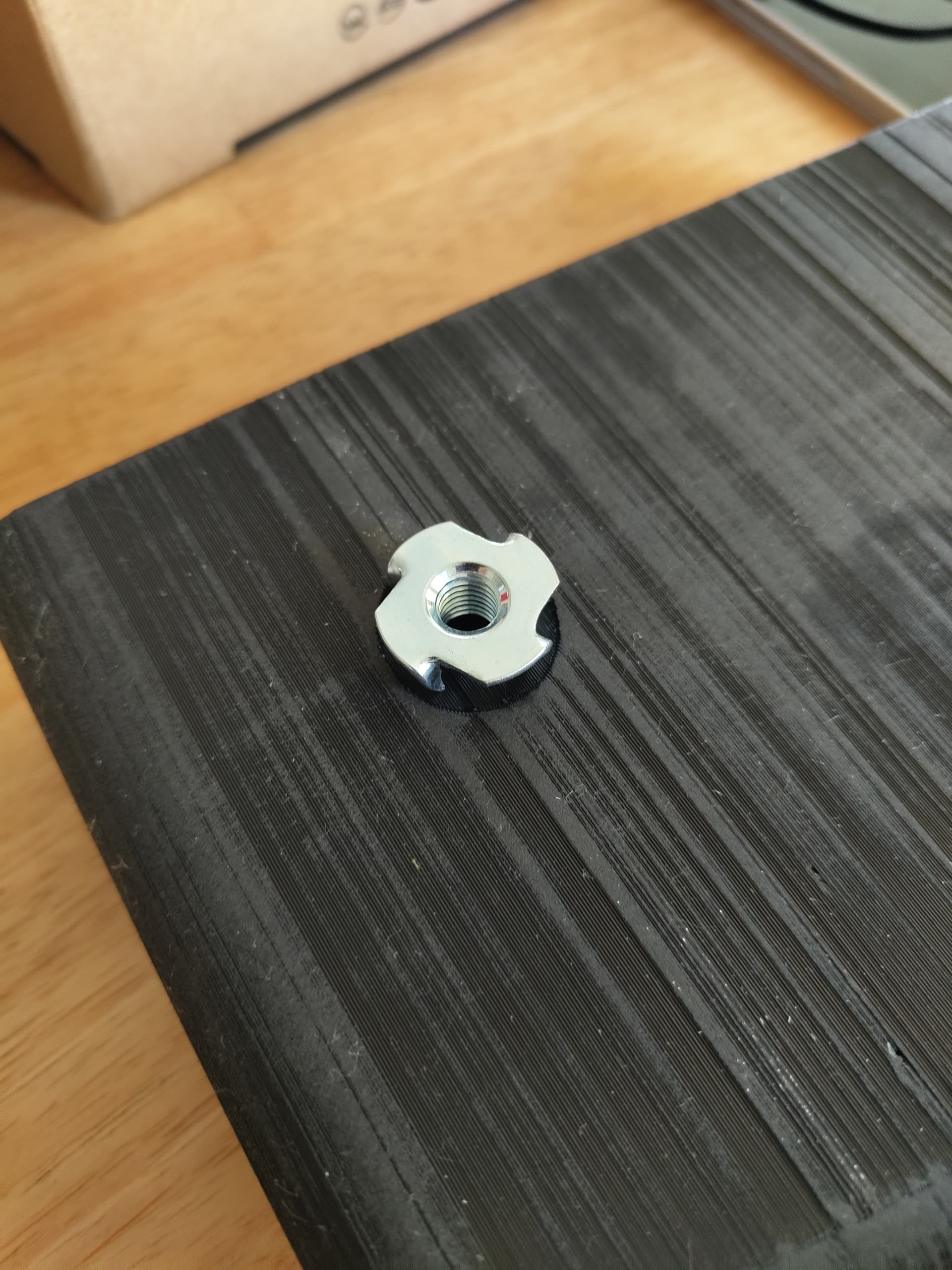
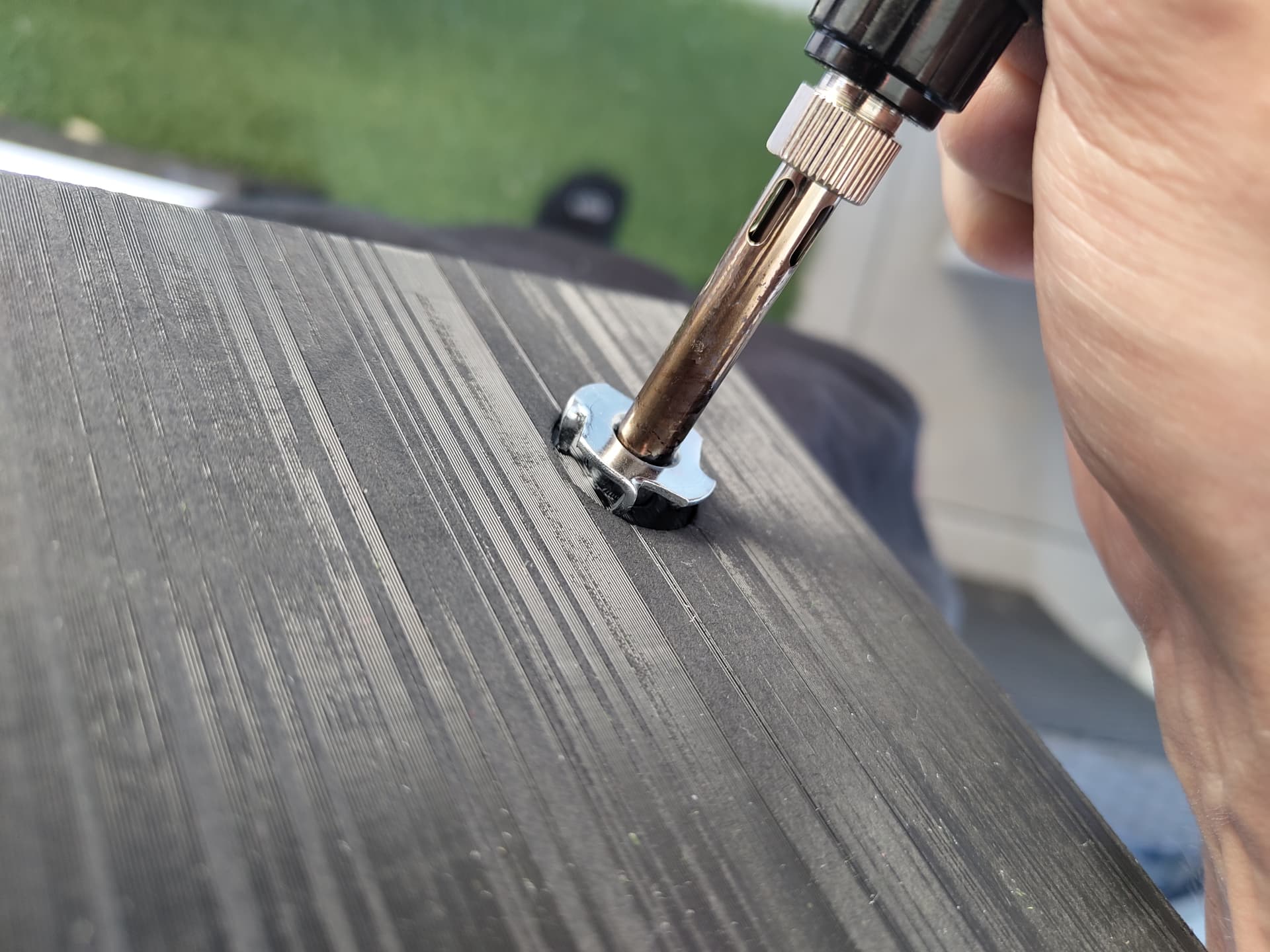
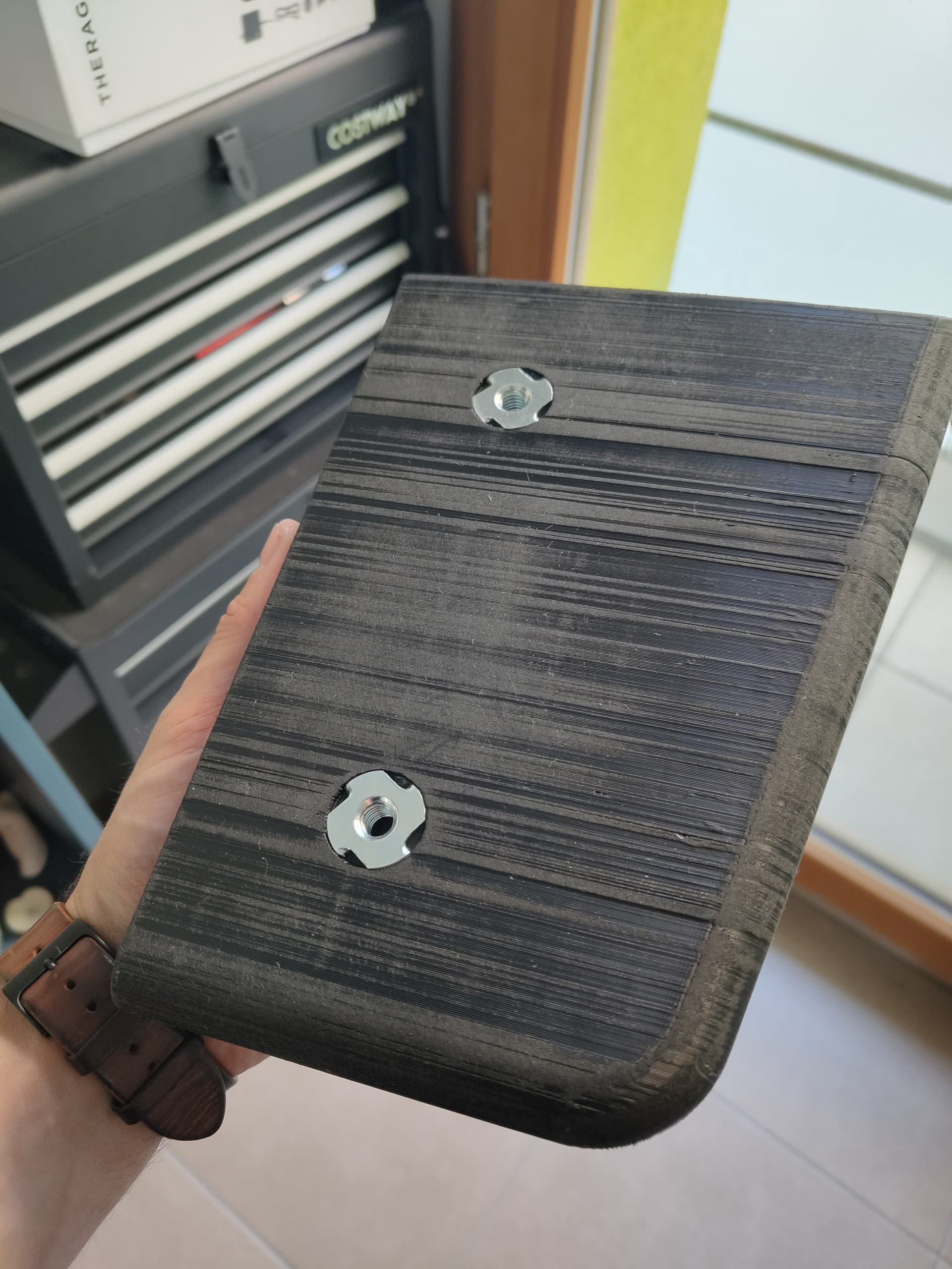
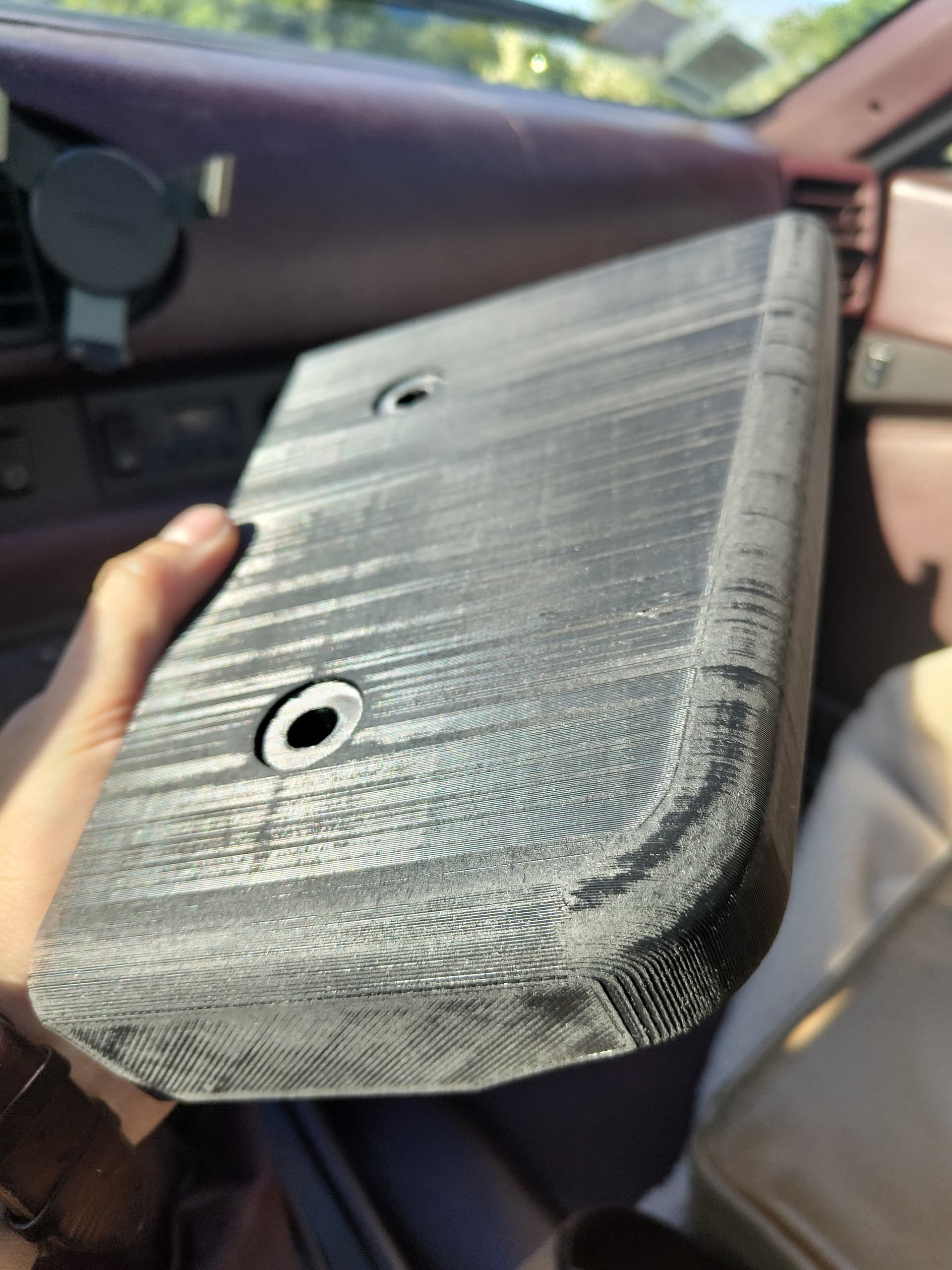
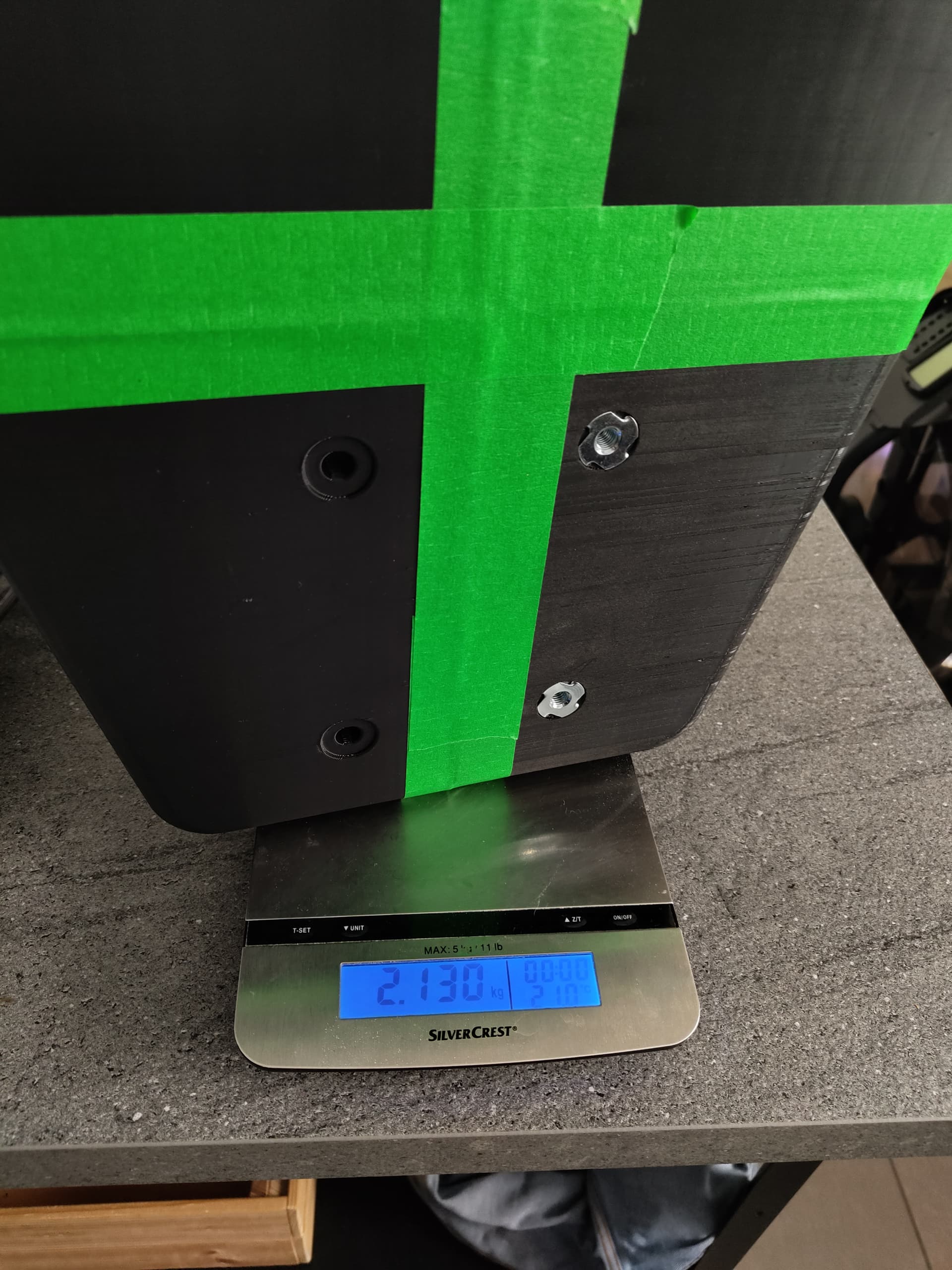
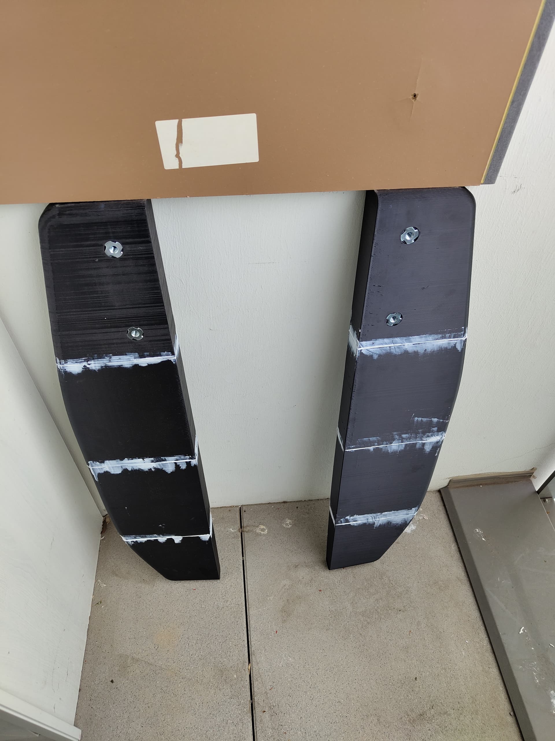
Mast screws as close as possible as the tubes to reduce loads on the plastic :

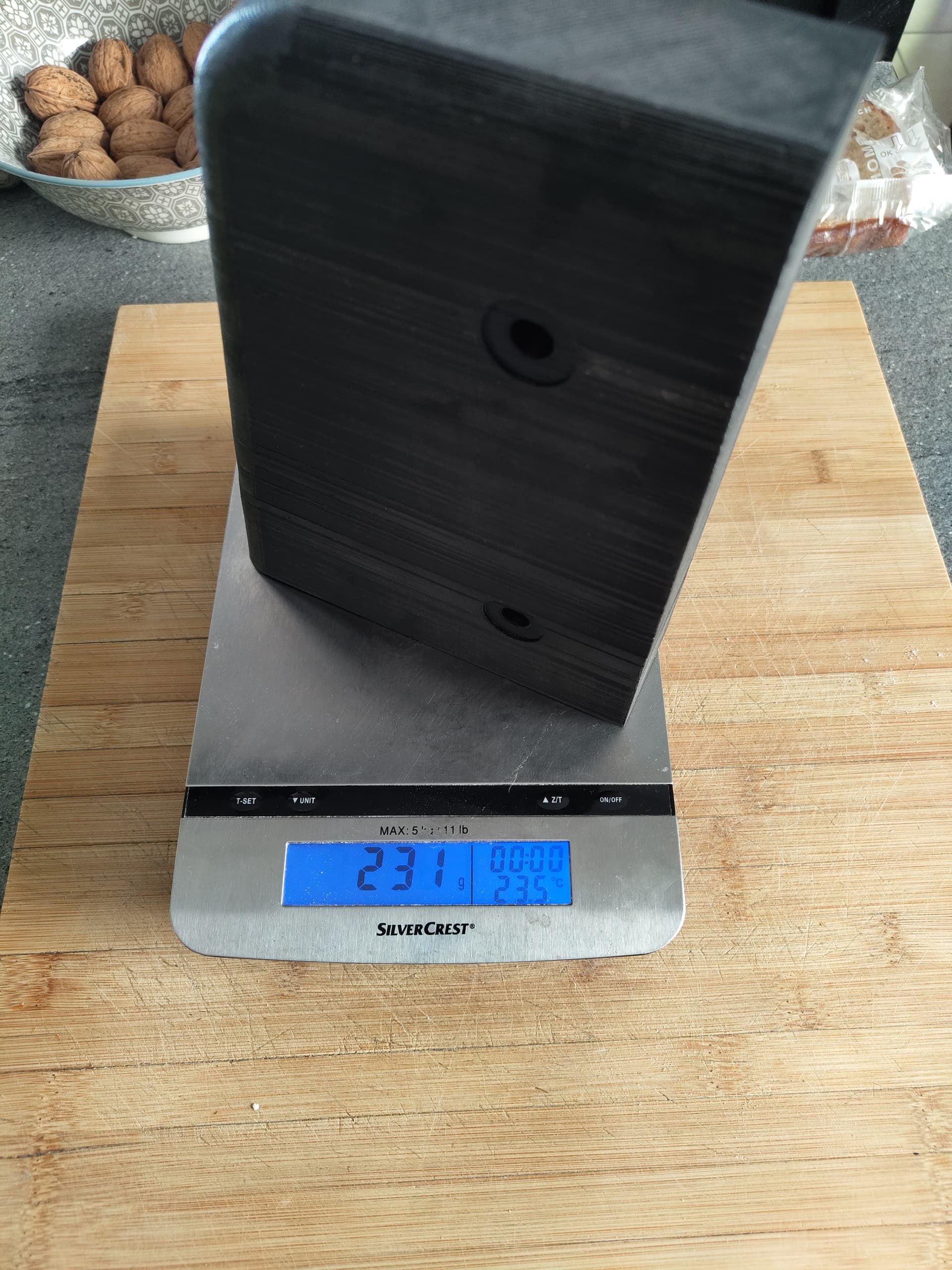
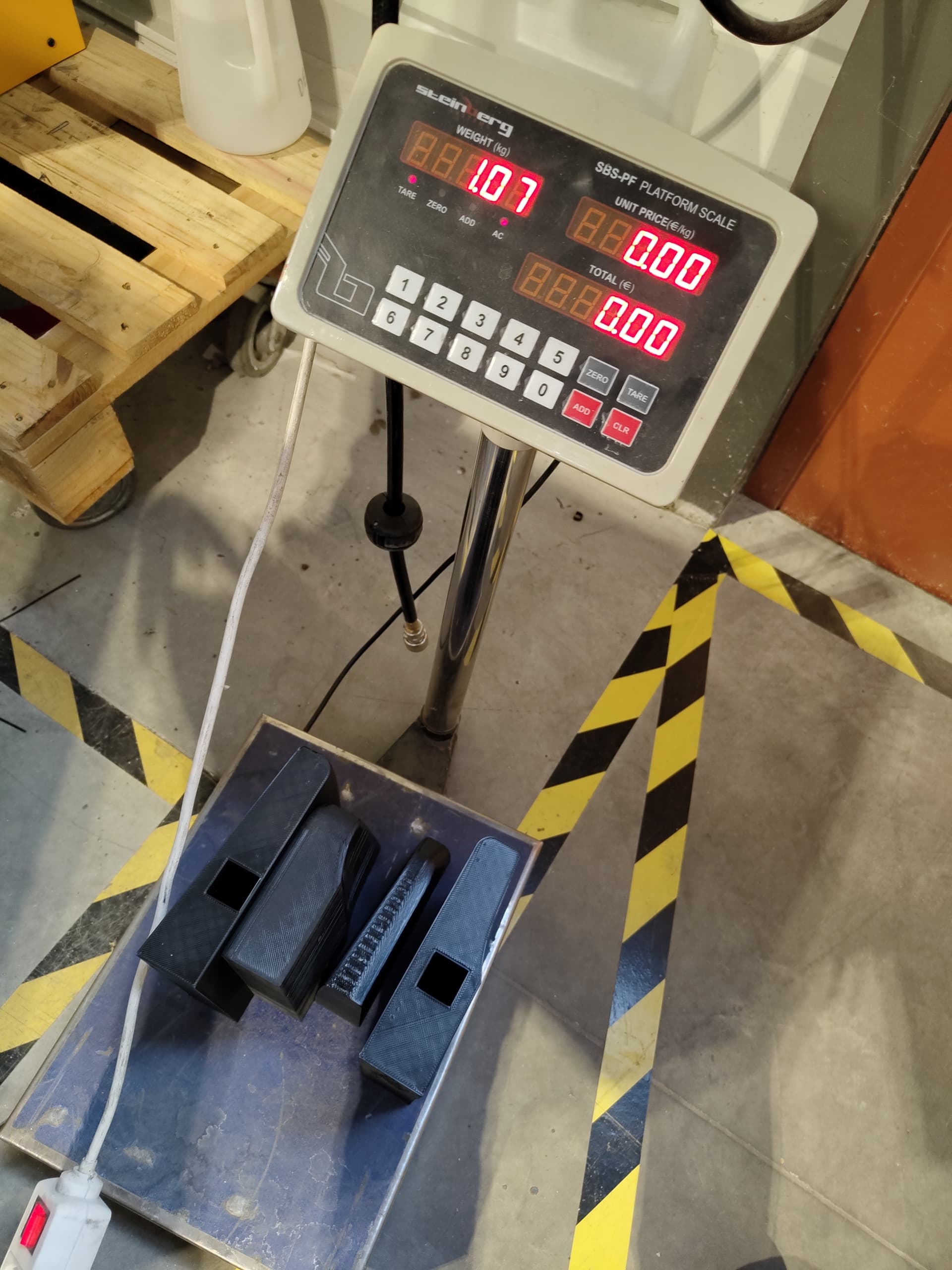
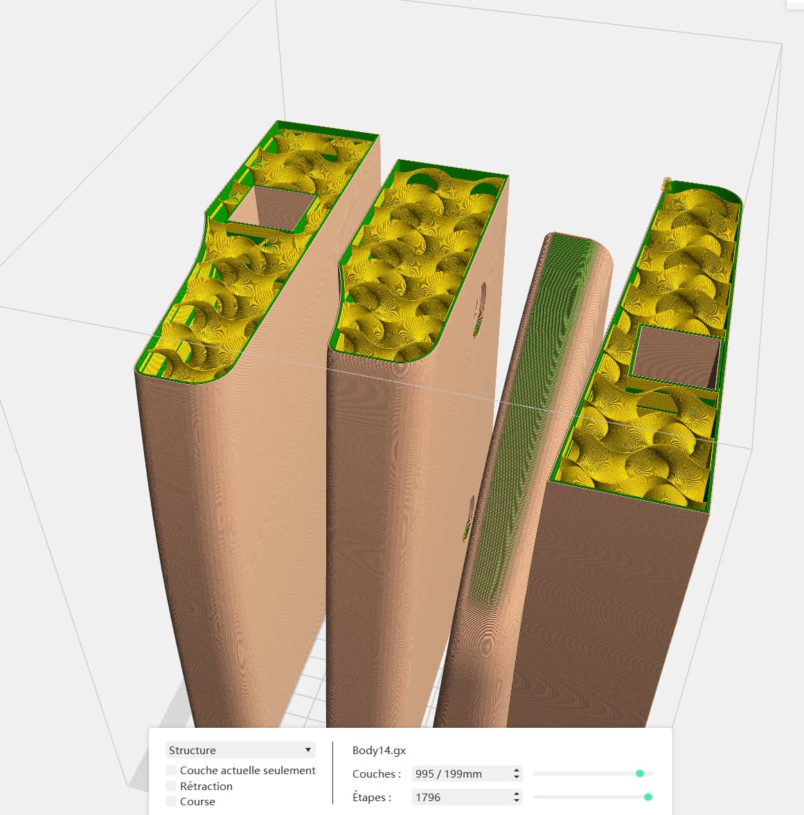
Quick verifications looks like I can have the 8 board parts for around 1.5kg, with low infill gyroidal.
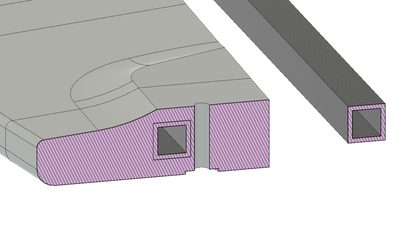

the danger zone

That’s as far as I got so far.

Next :

  • Lateral interlocking of the blocks, maybe just normal wood dowels
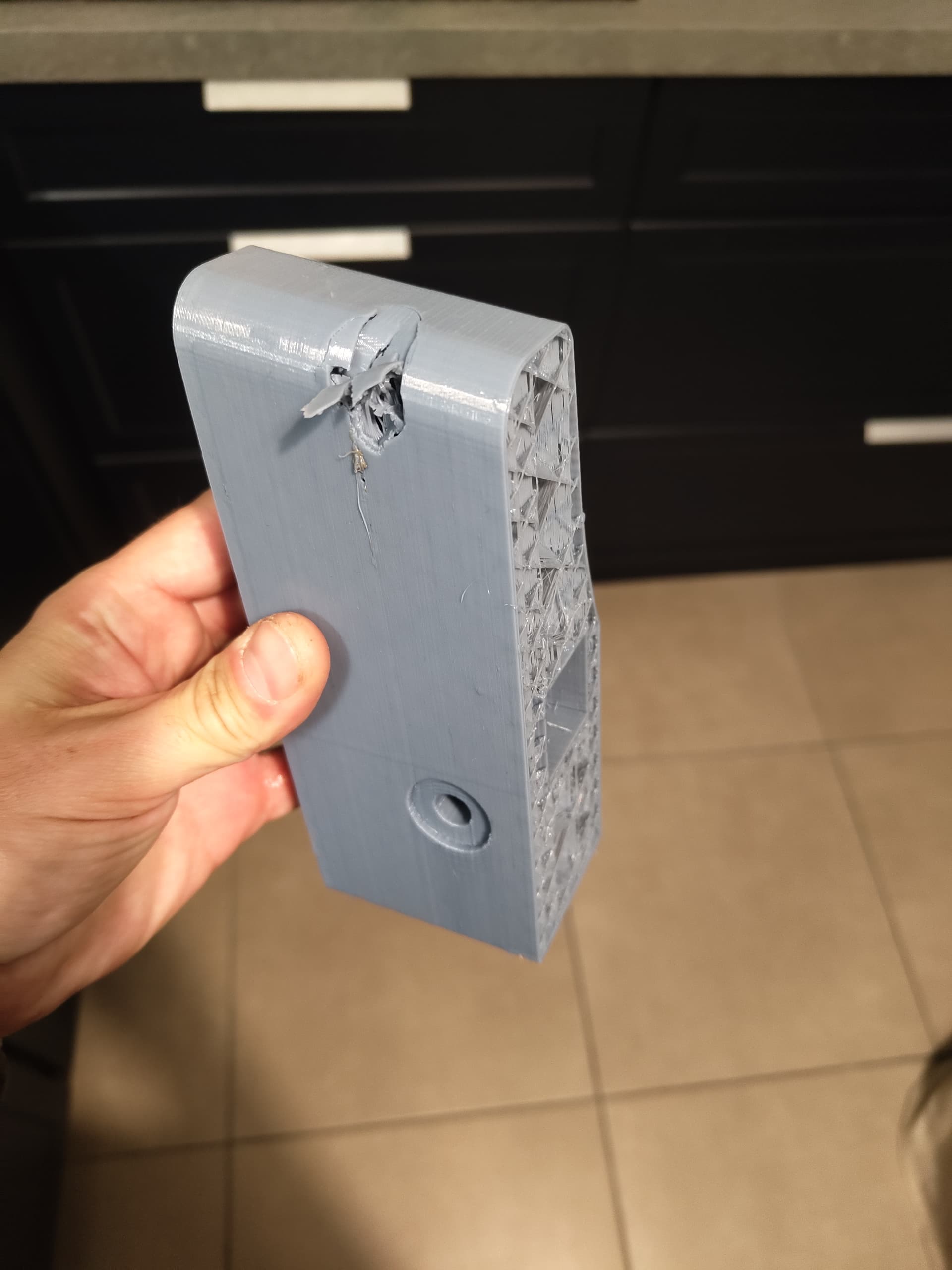
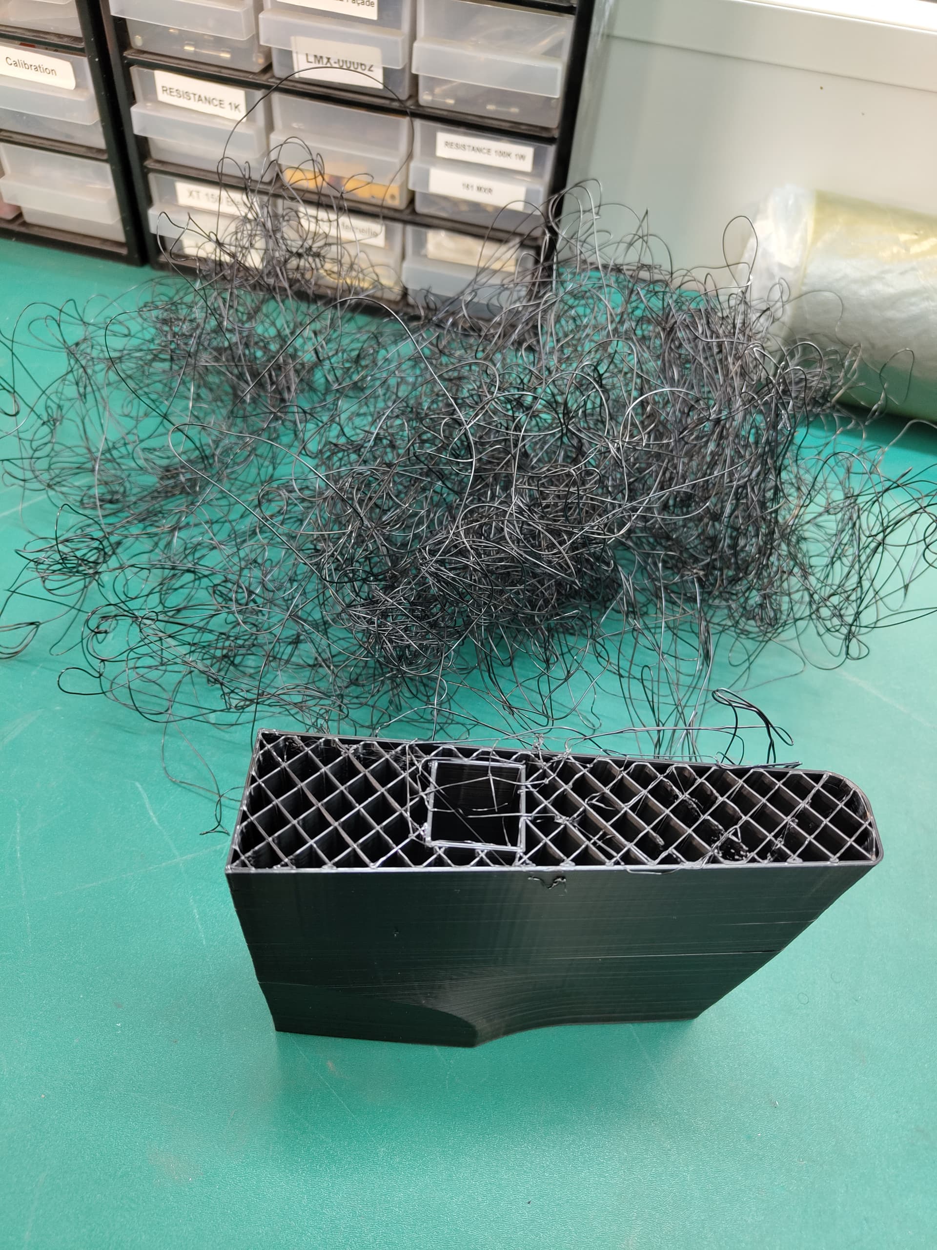
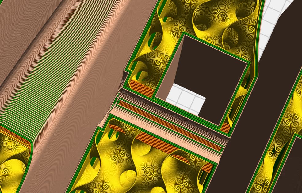
  • Infill optimisation to have closed cells
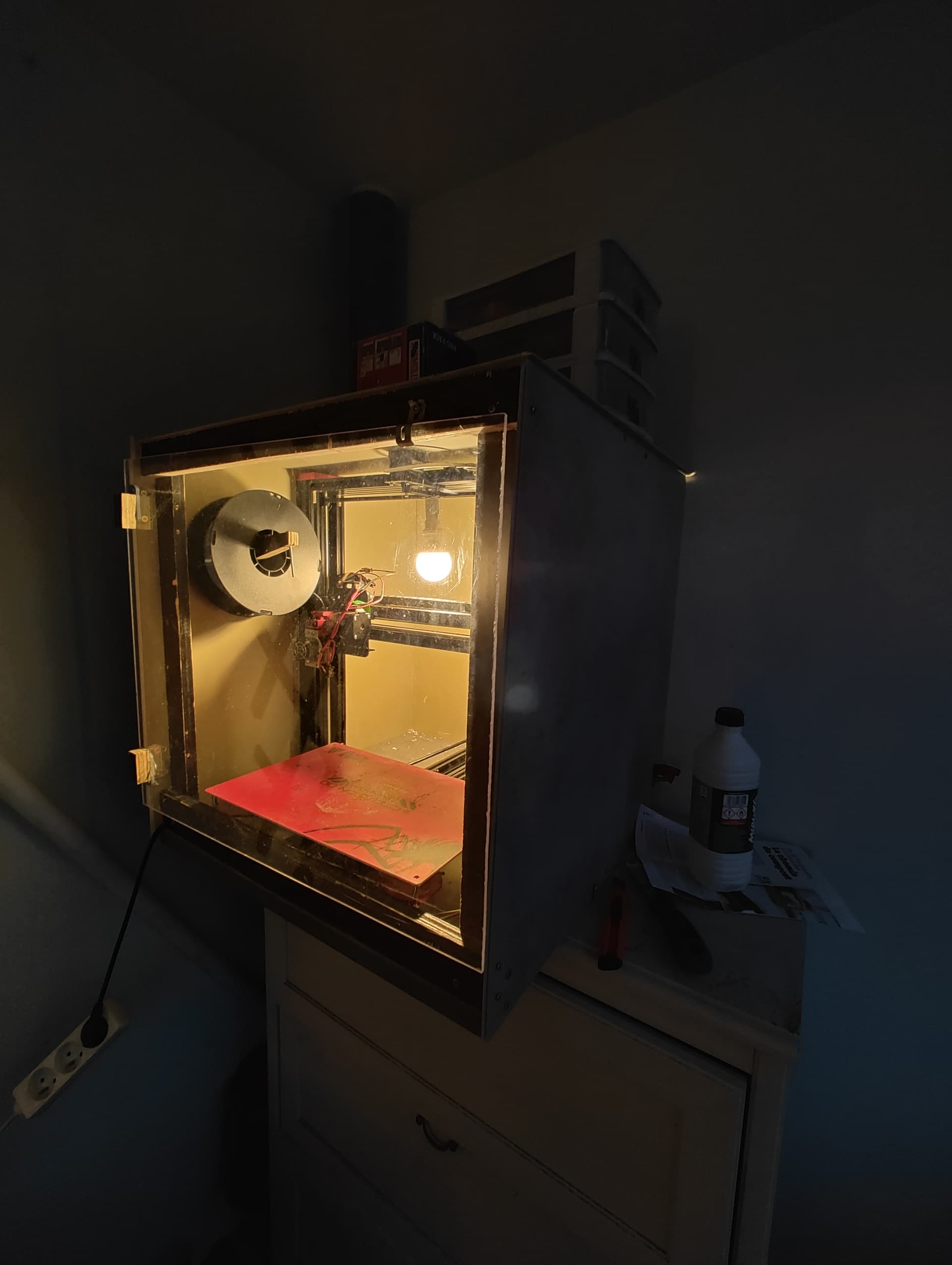
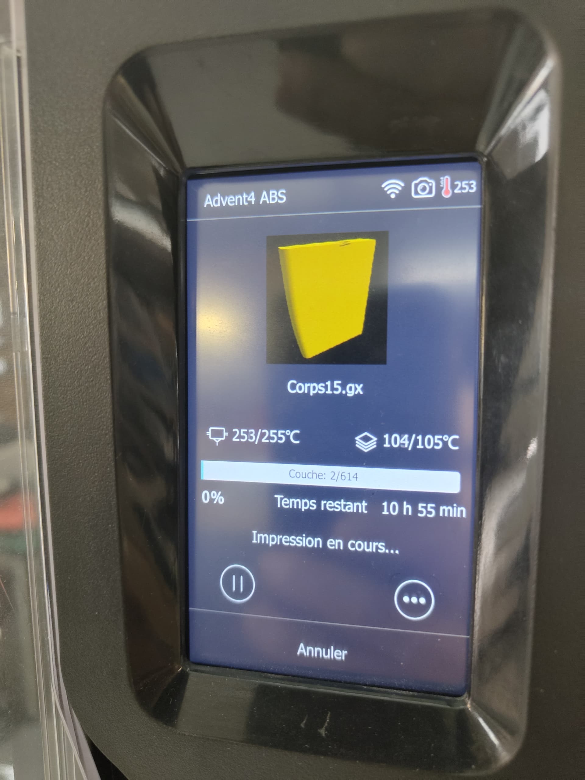
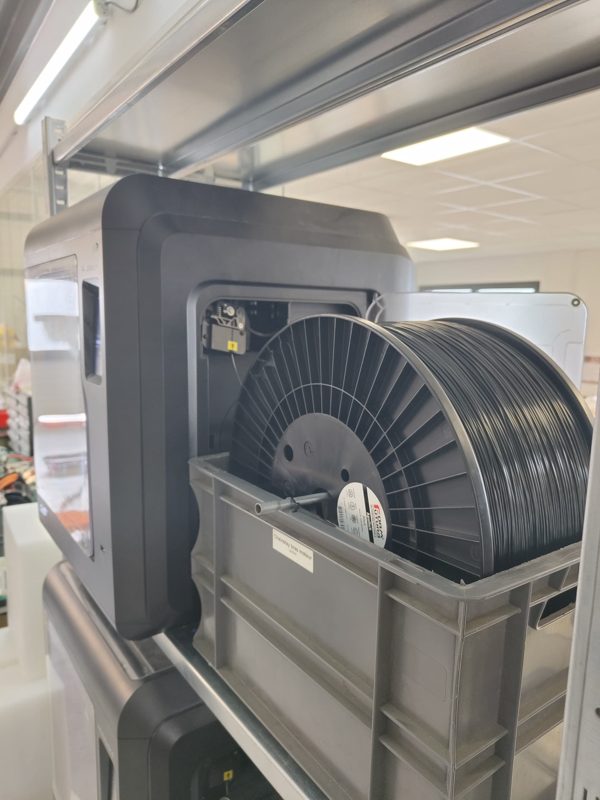
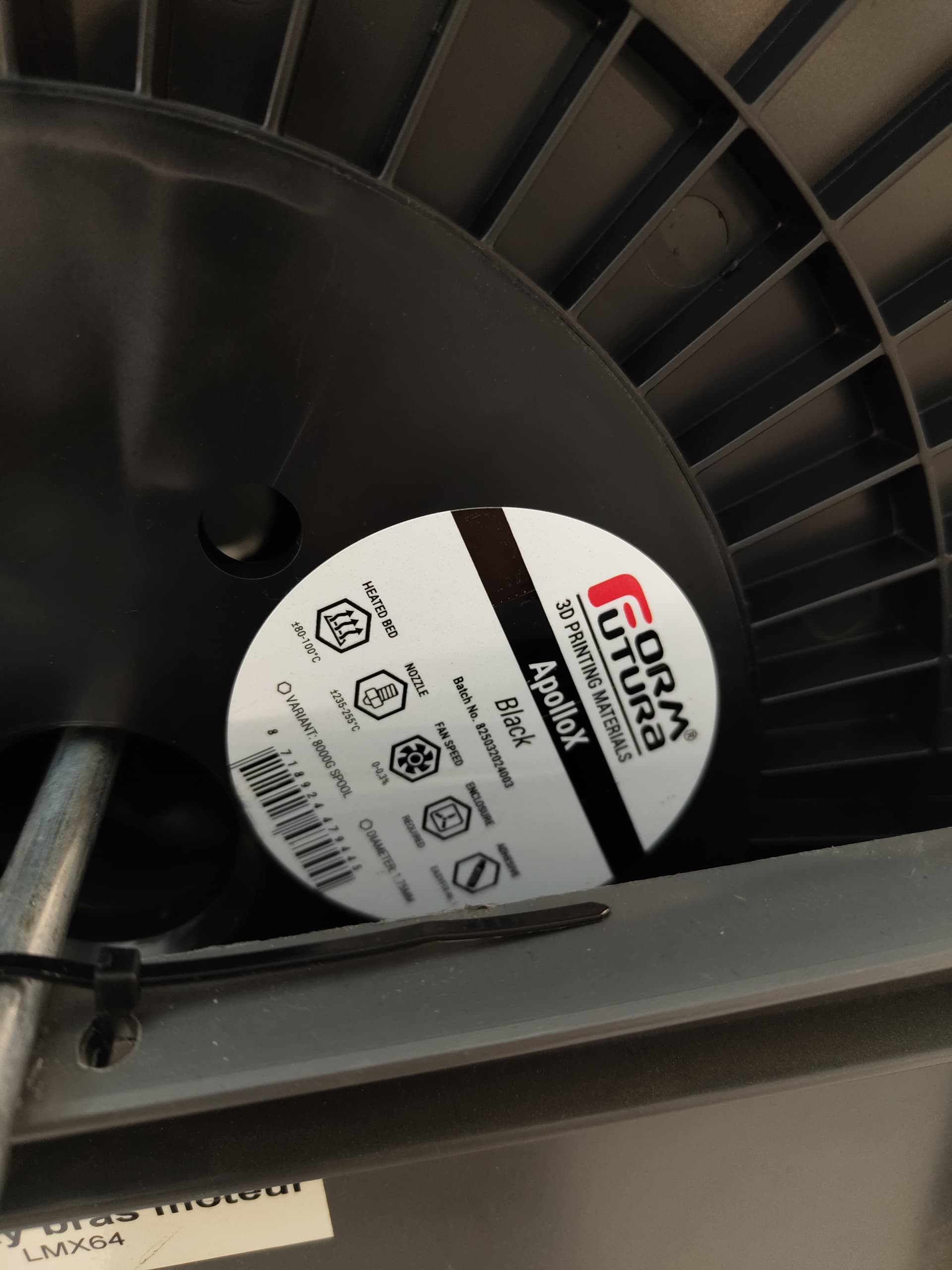
  • printing tests and material selection
  • find motivation for 60-100 hours of printing for a probable first failure after numerous print failures
  • find out if varnish or epoxy coat is enough to seal the print

Do you think it can be done? any recommendations?

4 Likes

I really want to see this succeed. Been planning for a similar design for a 3D printed frontwing at 80cm span and use of PC filament, no need for sealing PC from my understanding. I think alu profiles can be used while prototyping. 15 walls, gyriod infill at 40% was my plan A. Studied a lot of DIY airplane wing builds and aircraft composites on YT for inspiration. Ended up with the assumption of having to run 300g unidirectional CF across the whole span of wing/board even with internal alu/cf profile. Flex bending moment is intense and the youngs modulus numbers of all hobby filaments are really low compared to a single layer of 300g UNI CF infused at 40% epoxy. If that helps.
Idea here is a simple ”poor mans prepeg” saturating the UNI clot between 2 layers of plastic, spatula pressure to extract excess resin, finally placing the cloth in a pre-cut slot in the 3d print. This still does not solve the twisting forces that a 45 + 90 deg fiber direction would handle.

1 Like

I am making print tests now for work projects with ASA-kevlar 10% blend.
It is really rigid and layer adhesion is good.
My plan was 1-3 perimeters and 5% infill to meet the weight budget.
I will use alu for the prototype before I decide if I want to get the CF tubes, those will be 50-75€ alone.
The filament will be around 90€ if I go with the fiber reinforced ASA, 45€ for normal ASA.

My gut says you need more perimeters. 3 would probably be the minimum for printability, especially if your printer is not enclosed. The ambient air temp changes during such a long print will cause failures.

Print strength really comes from perimeters. Some good info on Youtube via CNC kitchen HERE. Jump to 8:22.

Also, you should consider running the mast bolts through the aluminum rails or redesign the mast connection area to be solid plastic. The infill will be fine for weight but it wont transfer the load well when you pump.

cool project.

I wanted to have the bolt just by the side of the tube, to avoid a failure zone where the tube is drilled.
With some tweaking I should be able to trick the slicer into having solid plastic collums for the foil bolts.
Here is the type of insert I am thinking about using on the top of the board :

My printers are fully enclosed and 110C beds
Still unsure if it will need a hot coat for waterproofing, or if 3-4 perimeters will be enough.

I think you will really struggle to justify the build weight. I also would use cubic infill instead of gyroid for sealled pockets but you need to either double wall or drop the layer height right down to get good sealing. CF and GF composite provide so much more strength in my opinion. At least with a pump foil it only needs foot placements and structural volume so I’m sure you can do it, I just think the build weight will be an issue.

1 Like

Found a supplier for the carbon square tubes, 48USD a pair in 700MM long.
making some test prints now in petg.
I think I will try to make a first version in petg or pla to validate the concept and model, then invest in more expensive matetials to print a second version.
10H print per piece using my normal printer. I have for work a couple of flashforge A4 and recently one A5M pro and this new generation of corexy printers is really something else. with 0.6MM nozzle, it is extremely impressive how fast you can get actual strong parts in asa or abs.

my “homeless” home printer that lives on my balcony

First printed section tests.
The flashforge 4M at work has a lot of hours, and needs some TLC (probably a loose belt) but the part came out strong and waterproof despite some layer wooble.
0.6mm nozzle (game changing for bigger parts), 75mm/min print speed and 0.35mm layers. Print took 8 hours, in ASA.
The threaded inserts were installed with the soldering Iron.


A second section is printing now.
The petg part was not waterproof and not as strong…

The looking between the two sides (left/right) IS still not figured out. I will glue everything with epoxy+filler, and hope the foil dodad holds both side together :rofl:

The thing that is scaring me is to loose the foil to the bottom of the lake if the board brakes. I will have to figure a safety leash or something.

The printer issue was solved, basically the whole head was Moving as the support of x axis is cracked and the threads gone. So now held together with a zip tie and hopes, the second part came out perfect with excellent adhésion to the bed.


I will go for a alu tube for this first version as it is available locally and cheap.

3/8


Half a board


what are the overall dimensions?

Looking at your print I was thinking it would be better to print 90deg from your current axis for strength. The way it is the weakest point is interlayer bonding. But if you are going to use carbon tubes it may not matter. Its a really cool project and I have considered it but my rough calculations found the weight was going to be too heavy. My 110cmx45cmx2cm carbon board which is bomber is 2kg all in. I make them from corecel m80…no shitty eps :wink: I hope its a success!

Missing two parts but now out of ASA, ABS is more tricky for the first layer adhesion.
The board is 82cm by 36cm wide

ABS, still much harder to print than ASA…

Waiting for 8kg Roll of asa

Back to the normal printing schedule
On the last stretch now! With 8kg Roll of asa from formfutura :hot_face:


1 Like

Printing done for V1
Now thinking about options for glue, one is PU mastic (good previous experience, very strong and tough, gap filling) or epoxy (more brittle, have to buy some light filler) acetone-ASA can also be an option apparentely. 2.1 kgs without the tubes, glue and pad. Around 80h printing so far


5 Likes

Glued both halves with alu tube


Used soudaflex 45 PU mastic. Had good results with this on other projects, not as rigid as epoxy… But much quicker.

Edit: 2kg650 on the kitchen scale, glued and with tubes, without pad. Feels heavy, similar to a 18mm plywood diy

1 Like

Looks good. Routing for you!

You might consider break testing it to failure at home before risking loosing a mast and foil to the bottom of a lake. Especially with all that ASA ready to make a second. From wake_theif’s pumping dynamics videos on Youtube, you should see about 2Gs of force on the board. If it was me, I would test it to twice or three times my weight before it hit the water.

1 Like

Yes really thought of that risk! Maybe I need to Come up with a leash of some sort for the first tests.

I have tried juming on the board laid on two support a few times, it feels very solid, but the real question is the board/mast connection, should have used some infill modifiers to get it stronger in a localised way.

Hope to be able to test it soon!