Amazing, looking forward to the build.
1 Like
I am not sure about this!
1 Like
Cool build. Just make sure you do your own due diligence, as it does read like “chat gpt”.
Also, skip the prop printing. Way too much work.
Just get a fliteboard prop, drill it out with the adapter here on the forum, and be over with it. Got me going around 50kmh with 15S.
2 Likes
I am not sure these connectors will work. The 65161 phase wires are 8awg and so are the esc phase wires. Those connectors say 12-14awg. Also they state 20A, I think a bit low for EFoil. I have my phase wires crimped to the esc wires, that of course is not for disconnecting.
You could try looking at trolling motor connectors, similar design but larger. Or go for Surlok connectors, those are common for efoils. If you buy the genuine Amphenol they are waterproof, but expensive
The — in his text are the telltale signs.
I do not even know how to get them with my keyboard.
Ps. Do you like the new mast my dad build for you?
He told me that there is a small surprise in it ![]()

A few comments since you asked.
-
I’m not sure your nose rocker is large enough. I use a Fliteboard (full size 100l) and the rocker (kicker) starts about 400mm from nose and rises about 140mm. Makes no difference when foiling but is a factor in takeoff, landing and touchdowns. Too little and you stuff the nose and the board stops!

-
The L size of V2 XOver is 1300 not the XL
-
I agree with @Kian that assuming the VESC doesn’t need cooling might be a mistake that’s hard to rectify.
-
Printing props and getting good results is harder than you seem to think. Flite prop is an inexpensive, proven, and long lasting option that is worth considering.
3 Likes
@HOF thanks man, excited to get started. Will post updates as parts arrive.
@Kian – fair point on the cooling. I’ll be monitoring temps through VESC Bluetooth on my early rides and will report back with real numbers. One builder reported 25C max on the remote with a 75200/65161 setup here: VESC Cutting Flipsky 75200 – though I know that wasn’t a sustained high-current thermal test. Another builder in the “to watercool or not” thread said passive cooling is fine on a 5ft+ board with volume, especially if the ESC is mounted on aluminum in contact with the mast baseplate: To watercool ESC or not? . Your setup with the PCB mounted directly to the aluminum base plate with thermal bridge to the mast is smarter than what I’m doing though. I might look into something similar instead of just sitting the ESC in a foam cavity.
@DutchFoiler – I did use claude to draft up the post and responses, I’m not a very good writer. However the design and component choices have been my failures / successes lol. Really interested in the Fliteboard prop suggestion. 50kmh on 15S is wild. Do you have a link to the adapter thread for fitting it to the 65161 threaded shaft? And what’s your full setup?
@S_Roger – you were absolutely right and I appreciate you catching that. Already cancelled the Cnlinko LP-20 order. 20A rated connectors on 80-100A phase wires is a no-go. Going with XT150 connectors packed with dielectric grease instead. They’re rated 150A peak, handle 8AWG, and the connection lives inside a sealed service cavity behind an O-ring hatch so they never see direct water. Builders on here and Endless Sphere have run XT150s on efoils in salt water for years with just dielectric grease, so freshwater at Lucky Peak should be fine. For charging I’m just using an XT60 inside the same cavity – open hatch, plug in, done.
Cells should arrive this week. Battery build first, then foam. Updates coming.
1 Like
You can find the drill bit here: Flite Prop Drill Guide by Caleb | Download free STL model | Printables.com
Maybe interesting to go with the QS8 plug? It will also do the precharging for you, I don’t think the XT150 does. You’ll need a big iron to solder those btw.
Oh and my setup consists of a fliteboard, 65161 120KV, 75200 Vesc, v2/v3 gong mast, gong curve V2 M, topped out at 50 with 15S. Now I’ve got a 16S with high power cells, so curious how much faster I will go.
Hey everyone,
Big update on my build. After spending a long night studying Gustav’s Danish V2 build thread and photos in detail, I’ve redesigned the board layout pretty significantly. The core components haven’t changed, but the board internals, hatch design, waterproofing strategy, and BMS have all been reworked. Wanted to share the changes and reasoning in case it helps other first-time builders thinking through the same decisions.
TL;DR: Switched from a two-cavity layout (service hatch + bolted battery hatch) to a single-cavity Gustav-style layout. Everything sits on one shared 1/2" birch plywood base plate that doubles as the mast hardpoint. Battery and ESC each live in their own sealed waterproof PETG enclosures inside the cavity. Single hatch with 4 compression cam latches for quick access. All electrical connections use XT150 connectors inside IP68 waterproof inline junction boxes. BMS upgraded from 100A to 150A with switch function for anti-spark power on/off.
What Changed and Why
Board Layout: Two Cavities → One
The original plan had the mast zone as a solid foam I-beam (deck-to-hull structural connection), with the battery cavity pushed forward ~21" ahead of the mast. A separate 6" Smartmarine screw hatch gave daily access to phase wire connectors and the power button.
Problems I identified before cutting any foam:
- CG offset: The ~10.5 kg battery sitting 21" forward of the mast created a significant nose-heavy moment. Manageable but not ideal for a first-time builder/rider.
- Structural complexity: Two cavities + foam wall between them + conduit channels through the wall = more cuts, more failure points, more fiberglassing.
- Daily access was clunky: Even with the service hatch, I’d be reaching through a 6" hole to plug in connectors and press buttons.
Gustav’s V2 showed a cleaner approach — one big cavity spanning the mast area, with everything mounted on a shared birch plywood base plate. The plywood IS the mast hardpoint AND the electronics floor. Battery and VESC sit on the same plate, directly over or near the mast.
My adaptation of his layout:
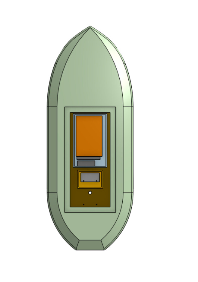
- Cavity: 26" × 11" (660 × 280mm), full through-cut on all 3 foam layers (same width), spanning from 11" to 37" from tail. Layer 3 has a shallow 1/2" recess in the top face around the opening for the hatch lid to sit flush.
- Plywood base plate: 1/2" (12mm) birch, 28" × 13" — extends 1" beyond the cavity opening on all sides, overlapping under the foam of Layer 1 for mechanical bonding. Epoxied into a shallow recess, flush with hull surface.
- Mast bolts: Rear section of the same plywood plate. M6 hex bolts from below, nyloc nuts tightened from inside the cavity. No more threaded inserts — simpler, stronger, replaceable.
- Battery CG: Now ~22" from tail vs 43" before. Only ~7" forward of the mast center instead of 21".
Hatch: Bolts → Cam Latches
The old design used 14-16 M6 countersunk bolts with E-Z LOK threaded inserts in a fiberglassed ledge. Bombproof seal but terrible for daily access — I’d never want to open it.
New design: 4× QWORK 316 SS flush-mount compression cam latches, one near each corner. Quarter-turn to open, quarter-turn to close. Lid lifts completely off (no hinges). Each cam has adjustable compression range (1-1/4" to 2-3/4").
The lid is 1/2" birch plywood fiberglassed with 3-4 layers 6oz on both faces, plus wooden braces on the underside — matching Gustav’s V2 spec. His V1 hatch leaked because it flexed; the V2 with the stiffer lid hasn’t leaked. Layer 3 has a shallow 1/2" recess carved into the top face around the cavity opening so the lid sits flush with the deck. TORRAMI 1/8" solid neoprene sheet gasket glued to the lid underside, compressed against the recess floor when the cams pull the lid down.
3D-printed PETG strike plates epoxied to the fiberglassed cavity walls give the cam hooks something solid to grab onto. The cams extend down from the lid through the recess and hook the strike plates on the wall, pulling the lid down and compressing the gasket.
Waterproofing: Trust the Hatch → Seal Everything
The old design relied on the hatch seal as the primary water barrier, with the ESC and battery exposed inside the cavity. After reading the thread about the Flipsky 75200 not being waterproof, and thinking through nosedive scenarios where the board goes fully underwater with force, I decided the hatch can’t be the only line of defense.
New strategy — everything is individually waterproofed:
Battery Enclosure: Gustav-style 3D-printed PETG body with aluminum plates top and bottom, M4 threaded inserts, sealed with thickened epoxy interior coating + silicone between plastic and aluminum. Contains the battery pack, JK BMS, 150A ANL inline fuse, balance wires, and NTC temp sensor. Single APIELE 12mm waterproof push button mounted through the enclosure wall, wired to the BMS switch input for power on/off (anti-spark soft start). Two XT150 female connectors on short 8AWG pigtails exit through PG11 cable glands.
ESC Enclosure: Same construction as the battery box — PETG body with 2mm aluminum plates top and bottom, M4 threaded inserts, sealed with thickened epoxy + silicone. Sized for the 75200 Pro V2 with VX3 receiver inside. ESC aluminum PCB face down against the bottom aluminum plate for heat transfer. Cable glands for all wire pass-throughs (2× power in, 3× phase out, reed switch, water alarm). Community reports 25°C max on the 75200 in eFoil use, so heat isn’t a concern even in a sealed box. All 4 aluminum plates (2 per box) cut from a single 12" × 12" sheet of 2mm 6061 aluminum (~$12).
The hatch with cam latches + neoprene gasket keeps out most water, but even if some gets in during a bad wipeout, nothing dies. The water alarm tells me about it, and I dry the cavity after the session.
Connectors: Bare Plugs → IP68 Waterproof Housings
This was a fun one to figure out. XT150 connectors are only rated IP40 — basically zero water protection. Trolling motor connectors are IP67 but expensive and only 50-100A. Cnlinko aviation connectors were my original plan but at $34+ per set they were overkill.
Solution: CESFONJER IP68 M25 inline junction boxes ($5.49 for a 2-pack). These are waterproof barrel housings with cable gland seals on both ends. The XT150 pair mates inside the sealed barrel. Unscrew the barrel to disconnect, screw together for an IP68 sealed connection.
5 housings total: 2 for battery power (positive + negative), 3 for phase wires. All connections are fully waterproof when assembled and fully disconnectable for transport. Foil separates completely from the board — zero wires tethering.
Packed with dielectric grease on the XT150 contacts for extra protection. At $27.50 for all 5 housings (bought 10 total for spares), this is way cheaper than any purpose-built marine connector solution.
BMS: 100A → 150A, Bypass → Inline with Switch
The original plan was a JK BMS BD6A20S10P 100A, discharge bypassed, with the ESC’s built-in power button for on/off.
Problems:
- 100A overcurrent protection could trip during hard takeoffs (DutchFoiler on this forum confirmed he hits 100A regularly)
- Bypassing discharge means no BMS protection for overcurrent, overtemp, or cell undervoltage during riding
- The ESC power button can’t handle anti-spark for the main battery connection
Upgraded to JK BMS BD6A20S15P 150A ($62 on AliExpress). Running it inline for both charge and discharge. The BMS switch wire connects to a waterproof push button on the battery enclosure wall. Power sequence:
- Plug XT150 connections (BMS is off, no current flowing, no spark)
- Press button → BMS soft-starts → ESC powers up
- Ride
- Press button → BMS off → safe to unplug (no current)
This eliminates the need for a separate anti-spark switch entirely. The BMS handles it.
Also upgraded the fuse from 100A to 150A ANL (BOJACK inline holder, $10.59 on Amazon) to match the BMS rating and avoid nuisance trips during takeoff.
Mast Mounting: Threaded Inserts → Through-Bolts
Eliminated all E-Z LOK threaded inserts. The mast now uses simple M6 hex bolts inserted from below through the hull fiberglass + plywood, with nyloc nuts tightened from inside the cavity. If a thread strips, replace a $0.10 nut instead of trying to extract and re-epoxy a $2 threaded insert from cured fiberglass.
Bolt holes are drilled after all fiberglassing is complete — using the Gong V2 top plate as a template held against the hull. No pre-drilling, no protecting threads during layup. Drill through fiberglass + plywood in one shot from below.
Gong V2 top plate sealed to hull with 3M 4200 marine sealant between the plate and fiberglass surface.
Updated Component List Changes
| Removed | Added |
|---|---|
| Smartmarine 6" inspection hatch | 4× QWORK 316 SS cam latches ($56) |
| E-Z LOK brass inserts (hatch) | CESFONJER IP68 junction boxes ×10 ($50) |
| E-Z LOK stainless inserts (mast) | BOJACK 150A ANL inline fuse ($11) |
| Frost King EPDM D-section seal | JK BMS BD6A20S15P 150A ($62) |
| Alex Tech wire loom tubing | LISTENJIALE 50pc cable glands ($14) |
| M6 countersunk bolts 50-pack | M6 hex bolts + nyloc nuts (Home Depot, ~$8) |
| XT90H connectors (charger) | 2mm 6061 aluminum sheet 12"×12" (~$12) |
| 1/4" birch plywood | 1/2" birch plywood (~$25) |
Net cost change: roughly break-even after returns and cancellations. The redesign actually saved about $20.
Budget is sitting at ~$2,880 all-in.
Updated Board Dimensions
Changed from 1524×650×120mm to 1600×600×120mm to match Gustav’s proven dimensions exactly. Slightly longer, slightly narrower. ~100L volume.
What Stayed the Same
- Flipsky 65161 120KV + 75200 Pro V2 + VX3 Pro
- Gong V2 complete foil setup
- 14S9P BAK N21700CG-50 battery (45Ah, 2.3 kWh)
- 3-layer XPS foam construction, hand-shaped
- 4 layers 6oz fiberglass each side, one layer at a time, no vacuum bag
- TotalBoat 5:1 epoxy with slow hardener
- Reed switch kill system on ankle leash
- jkoljo motor mount for Gong V2 (Thingiverse)
- 3D printed PETG propellers (MakerWorld STL)
- Lime green paint + black/green diamond EVA pad
Current Status
All parts ordered. Most Amazon items delivered or arriving this week. Gong V2 foil arriving Wednesday (faster than expected — UPS Express from France, though tariffs came in at $102 instead of the $89 I estimated). Battery cells + spot welder shipped via FedEx, should arrive Thu/Fri. AliExpress small parts trickling in over the next 2 weeks. BMS 150A is the last piece — estimated late April.
Planning to start cutting foam this week once I grab XPS from Lowe’s. Will post build photos as I go.
Thanks to Gustav especially — your V2 build thread is basically the blueprint for this board. And to DutchFoiler, Foilguy, sat_be, and HOF whose comments in that thread directly influenced the BMS and fuse upgrades.
— Derek, Boise ID
1 Like
Hey everyone,
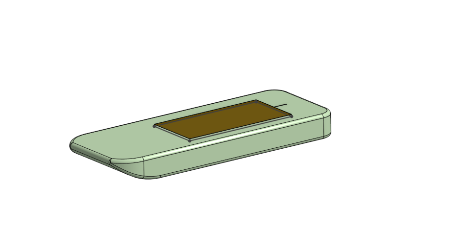
Quick update — spent the afternoon getting the board modeled in Onshape before I start cutting foam this week. Wanted to share the progress and get any feedback before I commit to cutting.
1 Like
Hmm, looks extremely bulk, almost like a brick. Try to make it less thick, and maybe you can make the sides more rounded? Get some inspo from the boards alreay out there.
2 Likes
Sharp edge at the bottom in the back is better for easy takeoff. Round corners cause trouble towards the end of the rails.
I made them round first and corrected it, see here, scroll down:
Works great.

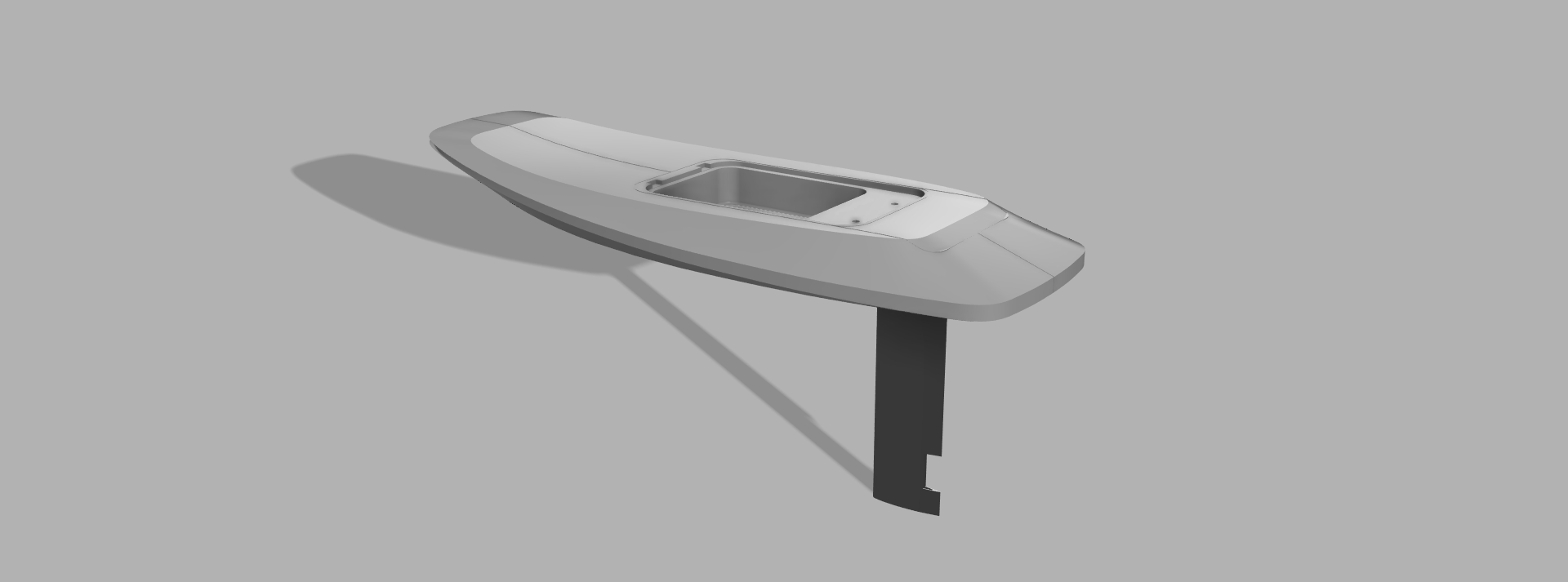
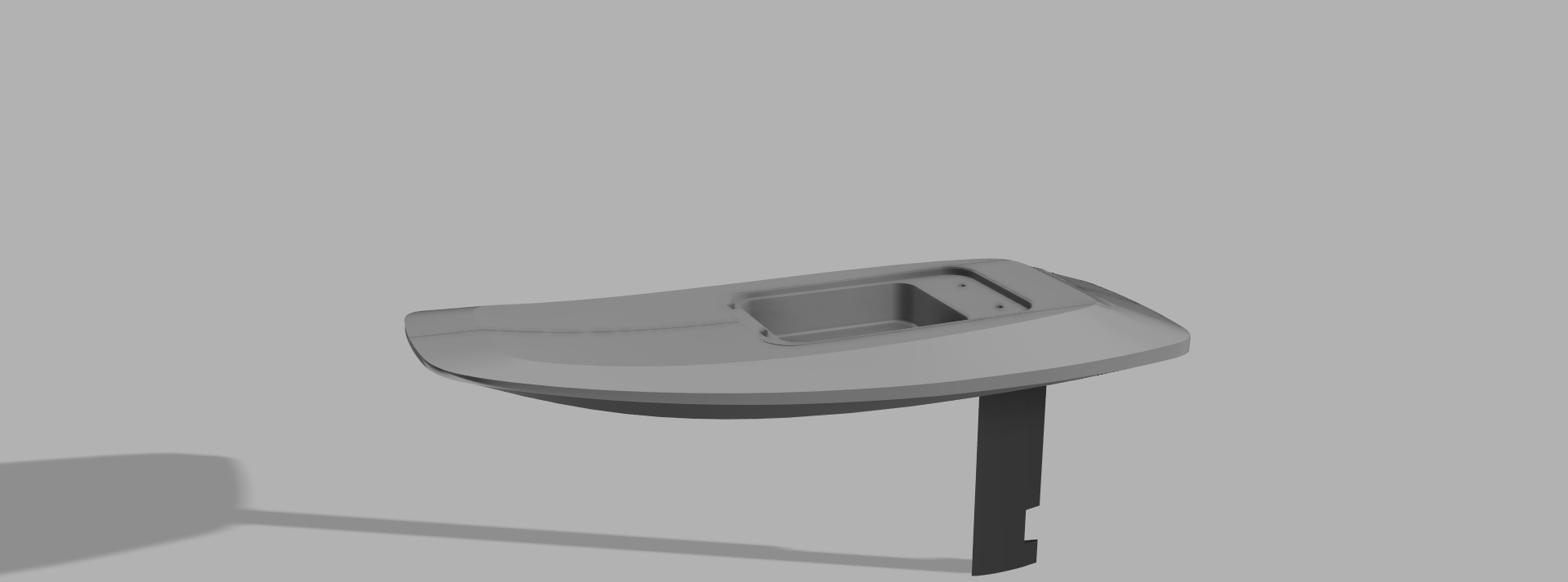
Big update — took all of your feedback and reworked the board shape in Onshape. Here’s what changed:
Board shape: Ditched the pill-capsule nose for a swept/tapered profile with 400mm fillets. Much less brick, much more eFoil. Tail stays blunter than the nose. Thanks @DutchFoiler for the reality check and @Kian for the Flite board inspo images — that wedge profile with the angled deck edge and flat sharp bottom is exactly what I was missing.
Rails: 20mm chamfer on the bottom edges (sharp, no rounding), 30mm fillet on the top edges. @sat_be your thread was exactly what I needed — sharp bottom-to-side transition for clean water release, rounded top for comfort. No more uniform rounding all the way around.
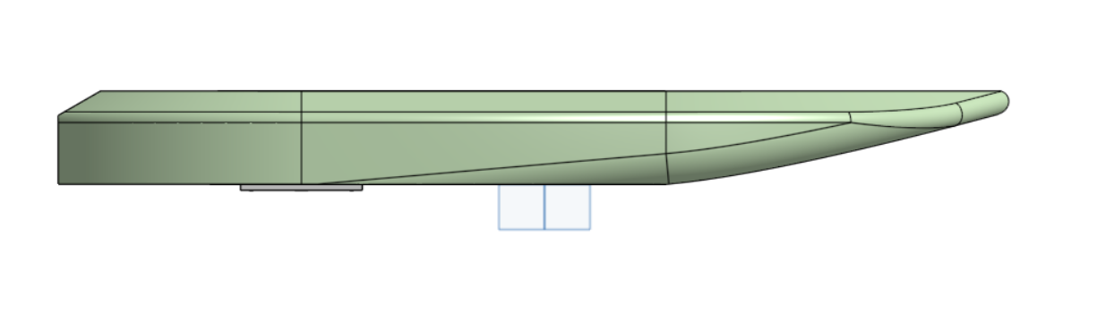
Nose bevel: Bottom surface now kicks up starting at 1000mm from tail (600mm from nose) instead of 320mm — way more gradual. Should help with takeoff and touchdowns. @Foilguy yours starts 400mm from nose with 140mm rise — mine is more gradual but starts much earlier, so the total rise should be comparable.
Thickness: Can’t go thinner overall — the battery enclosure just barely fits between the two 1/2" plywood plates with the cavity height I have. But I’m thinking I could build up the nose slightly (extra half inch on top that curves down to the 6" section where the enclosure sits) and/or do chamfers on the sides and tail to slim the visual profile, similar to @Kian’s Flite reference.
Other changes from this session:
- Solid tail increased to 300mm (was ~280mm) — more structural foam behind cavity
- Mast mount centered at 400mm from tail on a 90×165mm bolt pattern (confirmed standard via the mast/plate database thread)
- Battery and ESC enclosure walls upgraded from 4mm to 8mm PETG — cheap insurance for rigidity on 350mm+ spans
- Volume confirmed at ~77L via Onshape mass properties
Gong V2 foil arriving tomorrow. Cells should be here Thu/Fri. Will measure the actual top plate and verify bolt spacing before drilling anything.
Thanks again everyone — night and day difference from the first Onshape screenshot.
— Derek
Looks good. One more thing, the Volume in the tip does not help a lot, if you cut the tip and make it flat, it is much easier to place the board on wing and tip, it will not flip to one side.
2 Likes
Looking good @CaptainDerek. Since you’re in the USA, definitely check out SendCutSend for the aluminum plates you’re planning to esc and battery enclosures. I’m always happy when I find something I can order from them (instead of waiting for shipping from China).
For the esc box, you will want to use some thermal paste and work out some way to mechanically fasten the esc down against the alu plate. Glue is also an option but might make replacing the esc harder
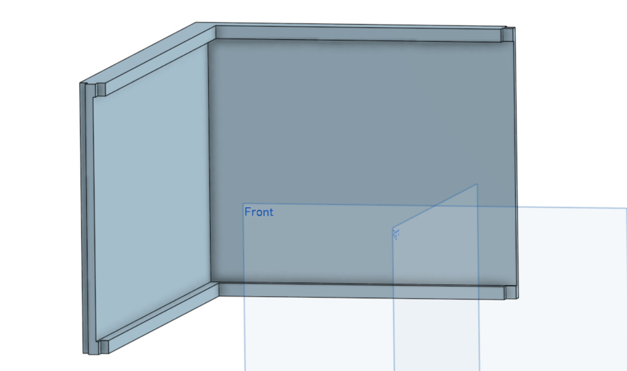
Sharing my enclosure plan before committing to print. Feedback welcome.
Constraints: board cavity 660×280×115mm (+4 mm due to lid compression ), 14S9P BAK cells (~211×339×70mm), JK BD6A20S15P BMS, Flipsky 75200 ESC, Bambu A1 printer.
Architecture: PETG walls + 4mm aluminum top and bottom plates, bonded with 3M 4200 on bottom plate, top plate gets Permatex Ultra Blac .
Walls: 6mm PETG, 104mm tall. Printed as 4 L-shaped corners (A1 bed can’t fit a monolithic box). Seams at wall midpoints with self-mating finger joints.
Shoes / Flanges: 4mm inward × 5mm tall projections at top and bottom of walls. Creates a 10mm sealing surface without eating interior vertical height. Pack can extend full 104mm interior since pack is narrower.
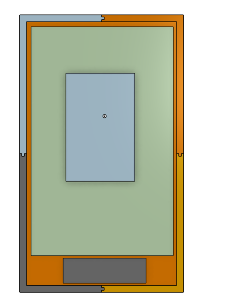
Sealing:
- 4200 at all permanent joints (wall seams, aluminum-to-shoe bonds)
- Permatex Ultra Black as FIPG between top aluminum lid and top shoe (razor-removable for service)
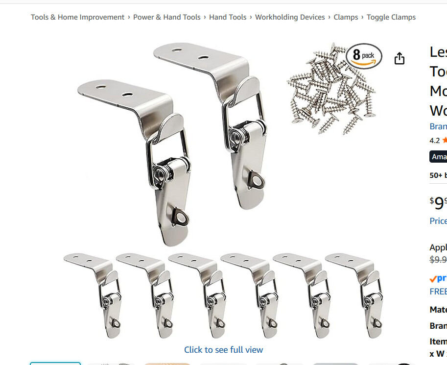
Lid closure: 6× stainless 90° corner toggle latches instead of ~30 perimeter bolts. Inspired by Eduard’s build from Germany. Side-mounted latch body fits in the ~18mm clearance between enclosure and cavity wall. Strike plates protrude ~2mm above the lid, which fits in available vertical space.
No dedicated charge port: charging goes through the same XT150 lines that feed the ESC. Disconnect ESC XT150s post-ride, plug in charger. Fewer penetrations, forces BMS off during connector mating (anti-spark workflow).
ESC enclosure: same architecture, smaller (~176×126×71mm). Aluminum plates provide thermal mass for passive cooling — ESC mounts face-down on bottom plate with thermal paste.
Anything obviously broken?
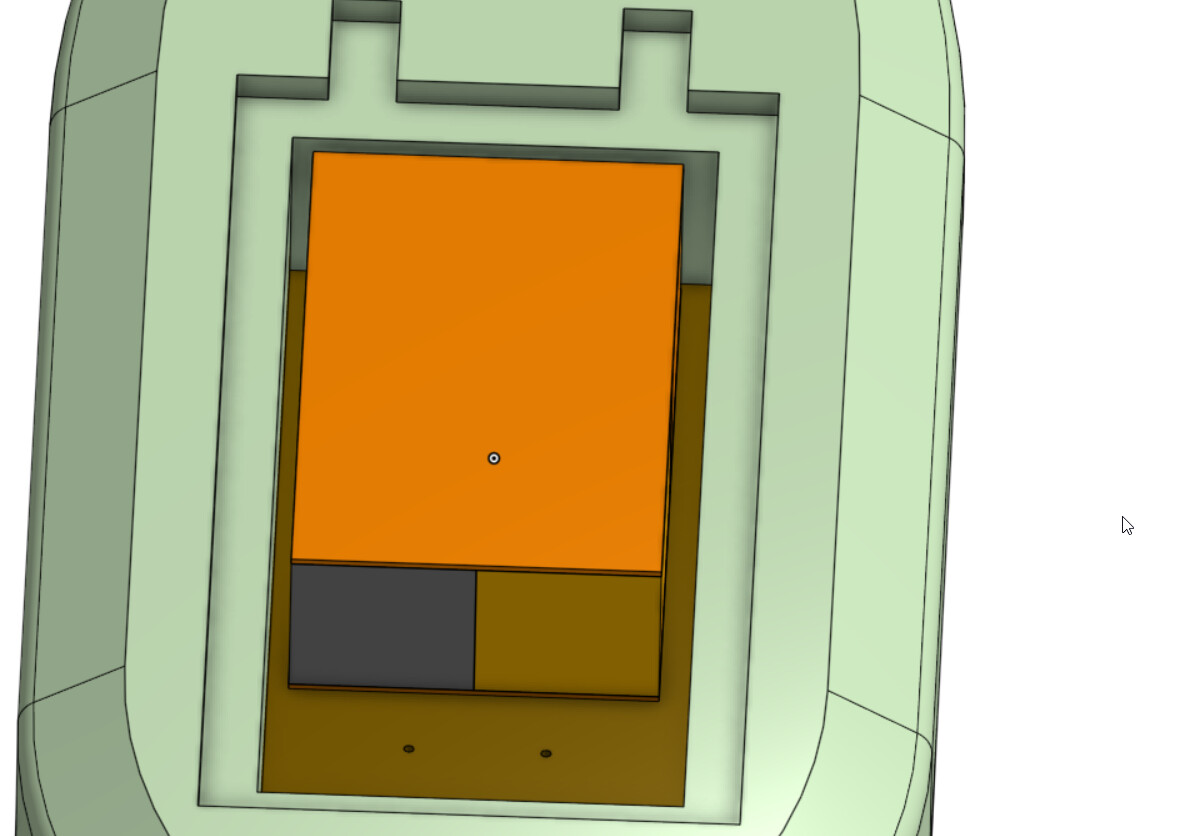
Latches I plan to use
Everything just barely fits, but I do have some margin to mess around with
The reason I didn’t want bolts is because I didn’t want to to have to make so many holes in the alu top plate and get them directly over the heat set inserts I would make in the plastic walls.
1 Like
I’ve been hard at work printing, assembling, and shaping the board and battery pack.
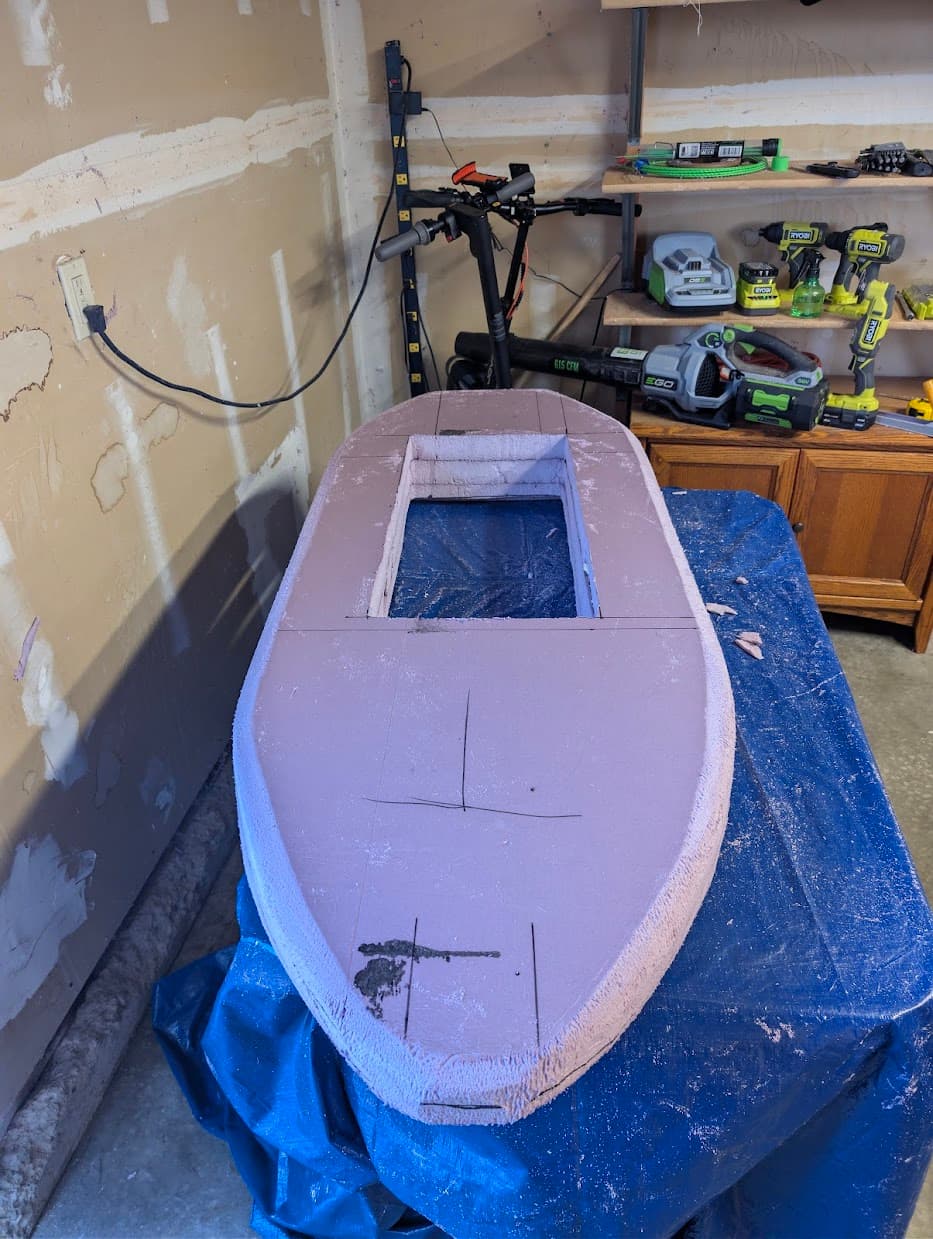
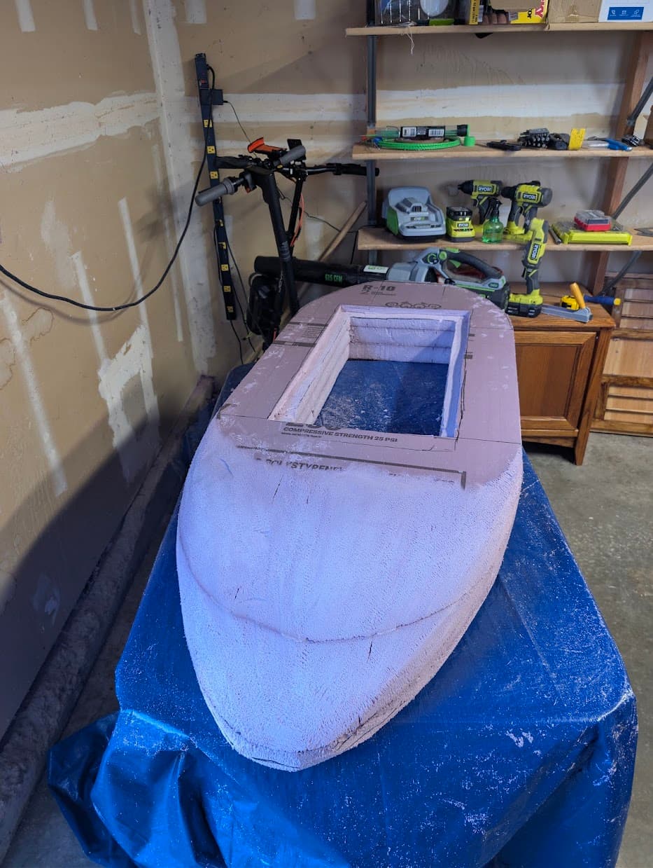
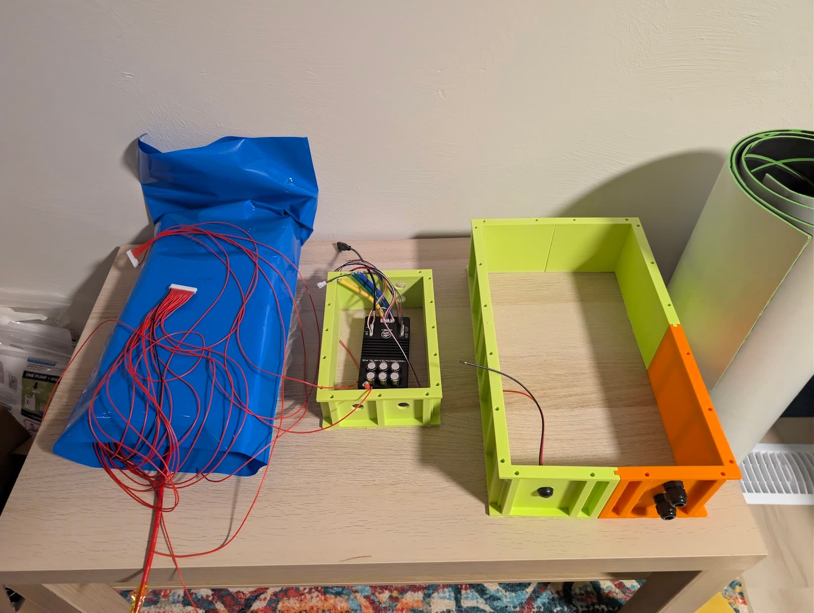
Battery pack is still not tested under load, but I expect to be able to do a full test of the electrical this weekend and start epoxying the board later this week.
5 Likes
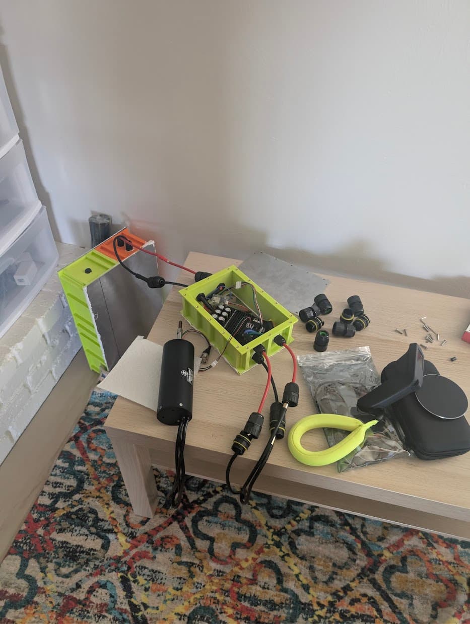
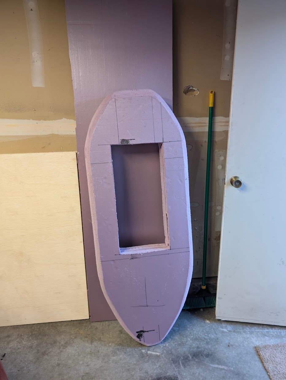
Electrical system fully hooked up e2e, tested, and confirmed working, so that’s fantastic!
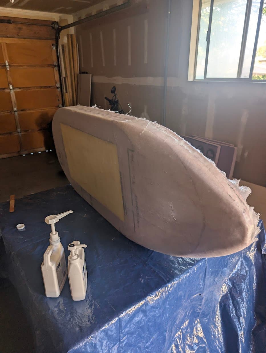
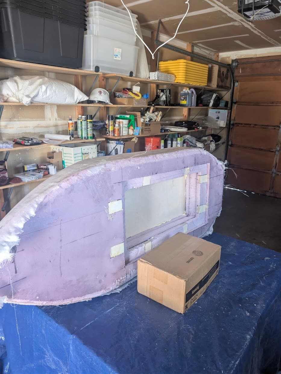
The epoxy and fiberglass progress is slow going, but I’ve made significant progress, I didn’t take a photo but the fiberglass on the top of the board is done, just working on getting the recess for the lid fully fiber glassed and flat for a good seal. Should be done with that today and start painting here next weekend.
2 Likes