@hangloose thanks Markus for this wonderful detailled thread. I have a small question please. Why don’t chosse the Flipsky VX3 remote which have tiny RX and great telemetry on screen (I have it). Is it a technical choice ? I would love a small response becaude Maytech is big and you don’t use Relay. Thanks again you rocks ! ![]()
Hi.
Thank you. @macfly1202
Back then I decided on the Maytech V2 because many people use the remote.
Since my Flydragon doesn’t output telemetry, this doesn’t matter to me.
The additional telemetry such as GPS etc. would be nice to have. But I can also do that with my Garmin watch.
But as an alternative I will remember the Flypsky V3.
Thanks for answer. To me only info that lacks on RC is mAH consumed not voltage. It’s so much easy in drone/RC area ![]() In reality BHeli32 have telemetry with proper firmware and connected to Betaflight or other drone unit could output in other protocol but what a complicated mess for so little data
In reality BHeli32 have telemetry with proper firmware and connected to Betaflight or other drone unit could output in other protocol but what a complicated mess for so little data ![]() If only Garmin, wtach could get telemetry with reliable link. ‘Your truly’ or other apps is great but only for VESC with bluetooth. Sorry for disgression. Thanks !
If only Garmin, wtach could get telemetry with reliable link. ‘Your truly’ or other apps is great but only for VESC with bluetooth. Sorry for disgression. Thanks !
I definitely need these, but for 8mm bullet connectors.
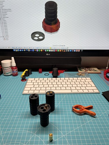
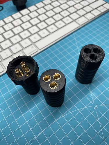
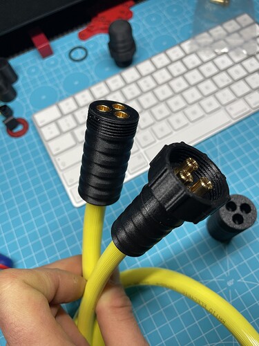
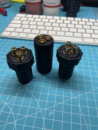
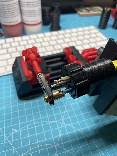
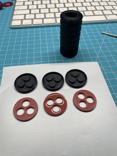
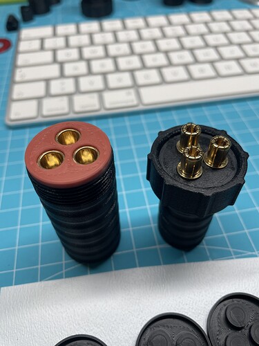
Yesterday evening I finished my LMT-6 connector including seals.
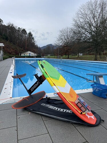
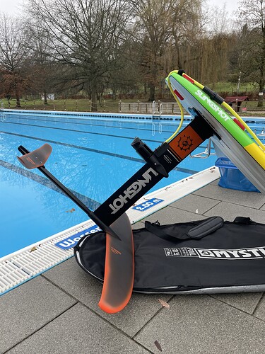
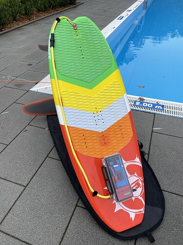
This morning I was in our outdoor pool for the first test run. Everything worked as it should.
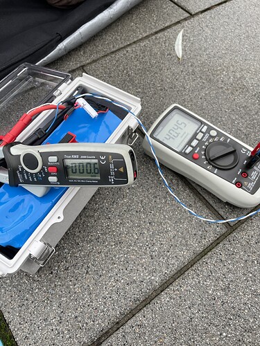
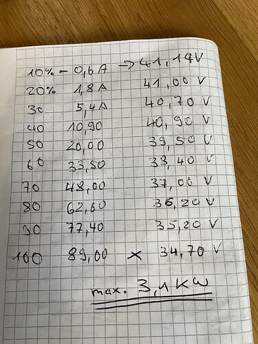
I measured the currents. I will replace the MTW-60 connections on my cables with the LMT-6 since a maximum of 100A phase current on the motor is borderline in the long run.
I’m so happy to have the Flydragon 150A.
Just plug it in and have fun. The heat sink remained lukewarm during the test.
Hi Markus
Great work mate.
Awesome build and very generous sharing all your amazing designs.
I have printed the waterproof housing for the MT-60, not sure where I’ll use it yet but I love it all the same!
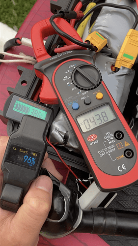
I was also testing current under load this afternoon.
Running the same 150A Flydragon on a 12S3P 18650 battery.
I could not see the current go over 44amps but the battery voltage started at 44volts so not fully charged.
Are you using any fuses/circuit breakers or BMS?
May have to try that one again with the battery fully charged.
Good luck with your build and I look forward to seeing more of your creations!
Thanks @cephalofoil
I didn’t install a fuse or anything like that. No BMS either.
If you have the same engine as me, we assume about 3.1kw. I=P/U.
With your voltage: 3100W / 43.8V = 70.77A. Somehow you’re missing a few amps.
Reasons could be another prop, your cells are not providing the required power or your Flydragon is not programmed for the gas path.
My LMT-6 waterproof Connector Design is online!
https://www.printables.com/de/model/675063-lmt-6-waterproof-connector-400a
I haven’t looked into programming the Flydragon. However I am quite happy with the amount of power it delivers even at that very low amperage.
Certainly my cells could be the limiting factor Samsung 30Qs.
Cheers mate
@hangloose
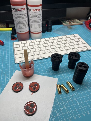
Your design of the connector and the self made silicon is exciting!
Why do you need a connector with 400A for less than 100A? I mean, the less resistance the better, but did you calculate that it is worthy.
It was clear to me that I didn’t need a 400A connection.
But since I wanted to remake my MTW-60, I thought I would create a larger connector that others might also need.
In addition, the connector is no larger than the MTW-60. Soldering is also much easier with the LMT-6 gold connectors.
And to mention that a brand new 400A can deteriorate a bit before it’s a 100A connector😀
I’ve had several xt150 connectors gradually go bad on my ebike in the winter, salt on the roads here are like running in sea water.
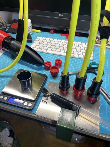
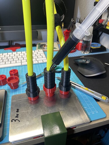
Epoxy filling the last on the plugs. ![]()
I simply printed my blind caps again. Then melted the inserts and screwed them onto the aluminum sheet.
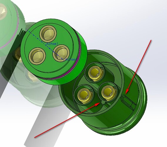
Seems you do not have any mark on the housing or some pin inside the connector so that the 3 wires always connect to the same one? If you rotate it 120 degree, you motor will run wrong direction.
On my system I have a small “nose”, and a mark on the outside so that the connection is always the same.
I didn’t put any markings on the plugs.
But I can see my Z seam from the printer.
Furthermore, it shouldn’t matter how the plugs are plugged in.
The phase field moves with it.
If so, you would have to swap two phases so that the motor reverses direction.
you are right, changing all 3 wires is no problem.
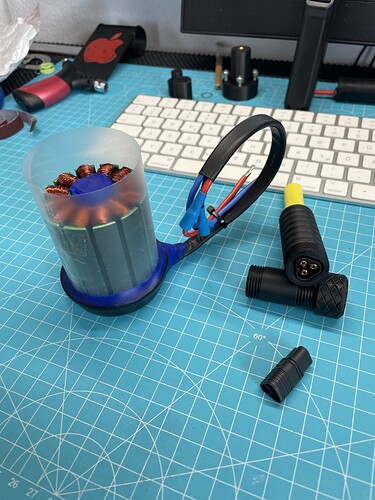
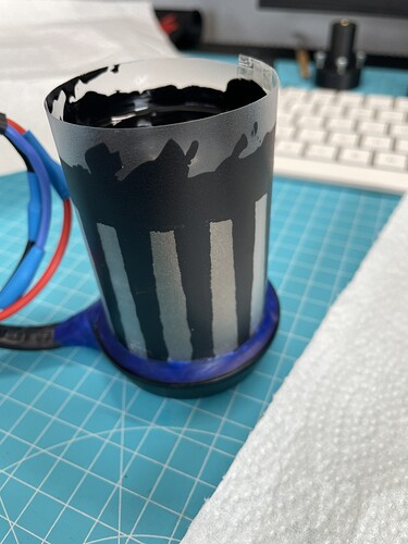
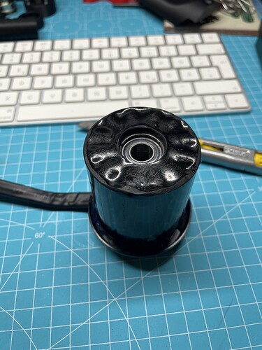
@hangloose do you have a more detailed picture on how you covered the bottom of the stator with putty when filling with epoxy? Did you just use a small amount to keep a small gap between the stator and cap?
Before filling with epoxy, I screwed in 8 screws at the bottom of the stator mount.
I let the foil around the stator run down to the bottom and then sealed everything on the side with putty.
So I don’t have a gap.
Perfect description exactly what I was wondering. Thank you!
