Sorry it’s too early for the sharing
I have to finish the assembly and the tests
but the snow is arrived in the alpes  so I have less time for the efoil
thank you yes in Switzerland, it is also very cold so I want to build an e-foil, have already bought various parts and printed 
I hope I hear and see something of you soon
greeting
koni
Its never too cold for testing, just get a proper wetsuit. Less heating issues with esc in the cold weather as well 
Notice the ice crystals on the floating dock.
stumbled on this, this evening, might be of interest, Penny + Giles Introduces New Low-Profile Magnet-Activated Rotary Position Sensor - Curtiss-Wright Controls Industrial
Yes sure Nikolai, and I have a drysuit for our cold lakes but now I prefer to enjoy the snow

Sorry for off-topic content
Looks nice! I’m still kiting on the water here in norway
Hi all, I wanted to revisit this topic. I am still riding with my ziplock bags and I am super tired of them now ![]() . So here are my Arduino tests. I believe @Hiorth, you guys went a similar path. All new to me and I appreciate any advice on components and my code and the libraries I am using.
. So here are my Arduino tests. I believe @Hiorth, you guys went a similar path. All new to me and I appreciate any advice on components and my code and the libraries I am using.
Here a quick video I just recorded going over my test setup: https://youtu.be/tj7eF9Sphb8
Here are the components and how things connect:
Here is the code:
I am looking forward to hearing your comments and suggestions. Am I on the right path with this setup?
Nice, @pacificmeister
The servo write works nicely you can also use the writeMicroseconds() for increased resolution on the PWM output.
Not much progress on the transmitter lately, still need to solve some safety issues. currently it is not stable enough for use on the water. Just used the wired version because it works to good.
I think a waterproof momentary/hall effect soft latching switch is nice as you mentioned. Hard to find a small waterproof ON/OFF switch.
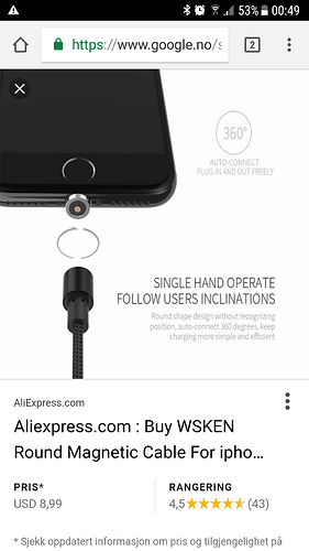
instead of the induction charger we are using a magnetic USB charger, same as found on cellphones.
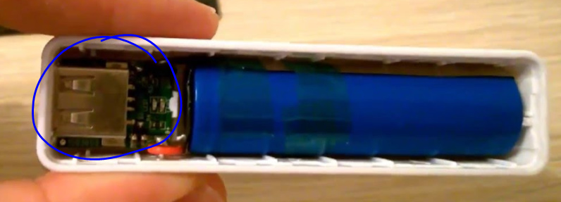
we also use a power bank with one 18650 cell. Very compact and safe in use, it also has the step-up and charging module included, you obviously to solder to make it more compact.
the hall effect setup I have described with rotating magnets works very well. High resolution and accuracy, much better than the RS component switch.!
Works, but need some debugging to be safe 
We use bluetooth modules and a dead mams button in case something jams
Great to hear @Hiorth , thanks for the quick feedback.
I read your previous mentioning about writeMicroseconds and I experimented with it. Not sure I can feel the difference between 180 and 1000 steps of throttle resolution. I was also thinking that fitting the throttle value in a byte sized transmission packet may have benefits on bandwidth/latency, but I am not sure if that makes much difference.
I also added the timeout now when the signal gets lost, a very good idea 
I will start with a case and throttle design next but need to wait for new mini-magnets to arrive, I had ordered them months ago but I can’t find them anymore argh…so many little packages to keep tack of.
Why are you guys not filling yor remote as much as possible with epoxy? I think that a homemade trigger is likely less reliable, than one that can get wet.
Hi Max, there is still the rotating potentiometer shaft, on/off switch and charging port that needs to be addressed if making a standard remote waterproof. People had good success with their own hall sensor based triggers, not just here but also on the esk8 side, I liked this one: Simple 3D-printed NRF remote - Arduino controlled - ESK8 Electronics - Electric Skateboard Builders Forum | Learn How to Build your own E-board. So while it might be quicker to waterproof a standard RC remote somehow, I like the idea of a fully sealed Arduino based approach a lot more. It gives us full control of everything, we can enhance and display all sorts of other data on the remote too. Especially once we all retire these seaking escs and move on to the VESC6 ![]()
Awsome link! Lots of valube info there!
Accelerometer + Gyro like the one below might be a good idea for a waterproof remote. No trigger or extra buttons.
https://playground.arduino.cc/Main/MPU-6050
Also adding wireless charging circuit could make a very robust and well water sealed build.
Hi,
I’m new to the discussion… The plan is to build a electric hydrofoil surfbard for the next spring/summer. Since it’s winter in Germany I started with the remote control.
I wanted to implement some features inspired form the videos of Pacificmeister (Grüße aus Heidelberg), and contribute to the discussion. sorry for my english in advance. Hope this will help somebody.
• Environment: the housing should be completely waterproof.
• Safety: the remote should not send a wrong signal if I loose it during the ride
• Energy consumption should be Low
• It should be lightweight and comfortable to use
I ended up with this Design:
I have no mechanical connection to the outside.
The On/Off switch is made with a REED-Contact (closing version). If the magnet on the outside is in position – the connection to the internal battery is asteblished. Theis magnet is attatched to a safety-leash. If I loose the remote – the magnet is released with the safty leash and the battery inside will be disconnected and the remote turns off.
The trigger s an elastic 3D printed part with an other magnet on the outsie and an linear magnetic field sensor (Hall-Sensor) inside.
There is also a bicolor LED to indicate status changes etc.
The core Components:
Sender:
• Arduino Pro Mini 3,3V
• RF24 Transiver Module
• Lipo Batery
• TP – single Cell Lipo Charger
• Bicolor LED
• Reed Contact
• Voltage regulator (3,3V)
• Hall Sensor
Reciver:
• Arduino Nano
• RF24 Transiver Module
Software:
reciver:
Very simple code… First an initialization phase with a sweep for the ESC (neeeded for the most controlers to calibrate). Then reciving and output the recived value to the ESC while the last recived Signal wasnt to long ago (interruption etc.)
/*
 *  used controler - Arduino nano 5V 328 16MhZ
 *  Used the RF24 transmitter
 *  Gives out a servo signal to the ESC
 *  uses power through the ESC BEC supply with 5V
 */

/*-----( Import needed libraries )-----*/
#include <SPI.h>
#include <nRF24L01.h>
#include <RF24.h>
#include <Servo.h>


Servo myservo;  // create servo object to control a servo
int pos = 0;    // variable to store the servo position (from 0 to 180)

// NOTE: the "LL" at the end of the constant is "LongLong" type
const uint64_t pipe = 0xF8E8F0F0E5LL; // Define the transmit pipe ( random 40 bit Hex number (12 hex didgets) but must be equal with reciver)
RF24 radio(9,10); // CE_Pin and CSN_Pin connections required
int reciveddata[2]; //variable array for recived data
bool radioreadseccessfull = false; //variable to check if read was seccesfull

// for fault detection the time from last recived signal will be measured
unsigned long timestampnow;
unsigned long timestampnext;
bool timeout;


void setup() {

   Serial.begin(57600); // enable serial comunication (for debugging purposes only)

  //setup the nRF24L01 Module
  delay(1000);
  radio.begin();
  radio.openReadingPipe(1,pipe);
  radio.startListening(); // put transiver in reciving mode
  radio.setRetries(1, 5); //if send is failed, retryafer 10*250µs, 6 times max
  //radio.setPayloadSize(12); // optionally, reduce the payload size.  seems to improve reliability
  radio.setPALevel(RF24_PA_HIGH); // pa level RF24_PA_MIN=-18dBm, RF24_PA_LOW=-12dBm, RF24_PA_MED=-6dBM, and RF24_PA_HIGH=0dBm.
  radio.setChannel(90); //set the equivalent channels for less intererence
  radio.setDataRate(RF24_250KBPS); // speed  RF24_250KBPS for 250kbs, RF24_1MBPS for 1Mbps, or RF24_2MBPS for 2Mbps (setting RF24_250KBPS will fail for non-plus units)
  //radio.printDetails(); //prints very detailed information for debugging purposes on the standard output


  // calibration routine for the ESC:
myservo.attach(6);  // attaches the servo on pin 6 to the servo object
delay(1000); //perform a delay to give some time to initialize
//perform 1 swipe for adjustments - 90° is still without rotation

for(pos = 10; pos <= 180; pos += 1) // goes from 0 degrees to 180 degrees
  {                                  // in steps of 1 degree
    myservo.write(pos);              // tell servo to go to position in variable 'pos'
    delay(15);                       // waits 15ms for the servo to reach the position
  }
  for(pos = 180; pos>=10; pos-=1)     // goes from 180 degrees to 0 degrees
  {
    myservo.write(pos);              // tell servo to go to position in variable 'pos'
    delay(15);                       // waits 15ms for the servo to reach the position
  }

} // never do 0° - then the controler needs readjustment -low power is 10° - this is experimental for every ESC


void loop() {


if ( radio.available() )
  {
    // Read the data payload until we've received everything

    radioreadseccessfull = false;
    while (!radioreadseccessfull) //read data untill you are seccesfull
    {
      // Fetch the data payload
      radioreadseccessfull = radio.read( reciveddata, sizeof(reciveddata) ); //
      //debugging
      // Serial.print("X = ");
      // Serial.println(reciveddata[0]);
       Serial.print(" Y = ");
       Serial.println(reciveddata[1]);

      //
    }
    if (reciveddata[0]== 26)
    {
    pos=reciveddata[1];
    timestampnow=millis(); //give me the time of the reciveevent
    }
     else // if reciveddata[0] is not 26 set the Motor to idle
    {
      pos=20;
      // Serial.println("reciveddata[0] is not 26");
     }
    }
    else // if radio is unavailable set the Motor to idle / maybe if it is braging you could work with mills to "bridge" short times when radio is unavailable
    {
      timestampnext = millis();
      if (timestampnext-timestampnow > 100) //if between the last recived number there is a timegap of 100ms - reset the value to 20
      {
      pos=20;
       Serial.println("radio is unavailable");
    }
    }

myservo.write(pos);
delay(10);
}
Sender:
Initialization of the RF module. Then an calibration phase for the hall sensor – here i have to use the trigger to define min and max position. The Values will be mapped to min and max.
In the main loop – reading the hall sensor and sending the Value. - indicate the Status with the LED.
/*
 * This is the software for the Sender (remote Sender) for the E- Bike project with a magnetic throtle
 * It utelizes a
 * Hall Sensor (S49E)
 * Rf Tranciver RF20L01 (works with 3,3V - gets distroied with 5V
 * and is powered with a lithium Ion cell with a connected controleboard
 * Code is written for an arduino pro (3,3V 8 Mhz)
 *
 */

/*Connections an pins
 * Hall Sensor needs ground and energy supply the signal pin goes to analogpin A1 on the Arduino pro
 * The RF20L01 is using 5 pins from the arduino plus powersuply and ground (total 7 connections)
 * The Battery is connected to the arduino via a switch
 * An indivating RGB LED should be implementable the rgb Led needs 2 PWM outputs for example pin 5 and 4

 RF20L01 connections - pins
 http://arduino-info.wikispaces.com/Nrf24L01-2.4GHz-HowTo
   1 - GND
   2 - VCC 3.3V !!! NOT 5V
   3 - CE to Arduino pin 9
   4 - CSN to Arduino pin 10
   5 - SCK to Arduino pin 13
   6 - MOSI to Arduino pin 11
   7 - MISO to Arduino pin 12
   8 - UNUSED

RGB indication LED should be implemented:
Red if something is wrong (radio reciver side unavailabel/unsessesfull send
blinking or somehow colour changing during calibration
indicating power level from blue to green

in the next version there could be a feedback channel with battery soc, esc temperature etc. but not for now.


*/
//  Hall Sensor
//  Gnd and VCC
//  Outputpin to Analogpin 1 (A1)
#define Hallsensorpin A1

// initialization of the sensor data
int hallsens_lowest;
int hallsens_highest;
int measuredval;
int numofCalibratinsamples = 600; // number of calibration samples
int calibrationtime = 5000; // Calibrationtime in ms

//  RGB LED
//  To grond
//  Digitsalpin 5 and 6

#define RGBPin1 5
#define RGBPin2 6


/*-----( Import needed libraries for the RF24 Module pins and variables)-----*/
#include <SPI.h>
#include <nRF24L01.h>
#include <RF24.h>
// NOTE: the "LL" at the end of the constant is "LongLong" type
const uint64_t pipe = 0xF8E8F0F0E5LL; // Define the transmit pipe ( random 40 bit Hex number (12 hex didgets) but must be equal with reciver)
RF24 radio(9,10); // CE_Pin and CSN_Pin connections required

/*-----( Variables for programm code)-----*/
int message[2];  // 2 element array holding the transmitted data


void setup() {

//define inputs and outputs
//pinMode(redledpin, OUTPUT);
pinMode(RGBPin1, OUTPUT);
pinMode(RGBPin2, OUTPUT);


  Serial.begin(57600); // enable serial comunication (for debugging purposes only)

//setup the nRF24L01 Module
  radio.begin();
  radio.openWritingPipe(pipe);
  radio.stopListening(); // put transiver in sending mode
  radio.setRetries(1, 5); //if send is failed, retryafer 5*250µs, 6 times max
  radio.setPALevel(RF24_PA_HIGH); // pa level RF24_PA_MIN=-18dBm, RF24_PA_LOW=-12dBm, RF24_PA_MED=-6dBM, and RF24_PA_HIGH=0dBm.
  radio.setChannel(90);
  //radio.setPayloadSize(12);
  radio.setDataRate(RF24_250KBPS); // speed  RF24_250KBPS for 250kbs, RF24_1MBPS for 1Mbps, or RF24_2MBPS for 2Mbps (setting RF24_250KBPS will fail for non-plus units)
  //radio.printDetails(); //prints very detailed information for debugging purposes on the standard output
  message[0]=26; // identifier that will be send and its kind of an identiofier the right remote etc.


//indication with led
analogWrite(RGBPin1,0); //turn indication LED off
analogWrite(RGBPin2, 0); //turn indication LED off

//measure the hall value during 3 seconds ( defined in calibrationtime after power up) to calibrate (schould move the throtle up and down completely in this time)
pinMode(Hallsensorpin, INPUT);
measuredval = analogRead(Hallsensorpin); //measure the value and store
hallsens_lowest = measuredval; //inital value (first read)
hallsens_highest = measuredval; //inital value (first read)
int calibrationsubsteptime = calibrationtime/numofCalibratinsamples;
int actualsubstepnumber = 0; //counter for while loop
int ledbrightnes = 0; // variable for indivation led status/brightnes
// unsigned long actuallmills = millis(); //capture actual processing time

// start calibrating
while (actualsubstepnumber <= numofCalibratinsamples){
  measuredval = analogRead(Hallsensorpin); //measure the value and store
  hallsens_lowest = min(hallsens_lowest, measuredval); //if measuredval is lower, it will override. min() returns lowest value
  hallsens_highest = max(hallsens_highest, measuredval); // is value is higher than before it will be taken
  actualsubstepnumber++;

   //indication with led
  ledbrightnes = ledbrightnes+10; // led brightness depending on while loop counter (from 0 to 255 will overfloat several times)
  //indication with led
  analogWrite(RGBPin1,0); //turn indication LED off
  analogWrite(RGBPin2, ledbrightnes);  //turn indication LED on during calibration fade to bright (red)
  delay (calibrationsubsteptime);
  }
//indication with led
 analogWrite(RGBPin1, 200); //turn indication LED on for secsessfull calibration
 analogWrite(RGBPin2, 0); //turn indication LED off

delay(1000); // give time to initialize veverything including radio


}

void loop() {


  //read the hallsensor value
  measuredval = analogRead(Hallsensorpin);    // read the input pin A1 (analog) where the hall sensor is connected

  message[1] = map(measuredval, hallsens_lowest, hallsens_highest, 20, 180 ); // map the result to the calibrated values
  message[1] = constrain(message[1], 20,180); //check if value isnt out of range


//debugging
    // Send the hall Sensor Value
    Serial.println("Now sending...");

  bool transmissionseccess = radio.write( &message, sizeof(message) );

    if (transmissionseccess)
    {
            analogWrite(RGBPin1, (message[1])); // indicate sended and transived data with green led brightness
            analogWrite(RGBPin2, 0); //turn indication LED off
            //(Serial.println("ok\n");
            Serial.print(measuredval);
            //analogWrite(redledpin, message[1]);
            //analogWrite(RGBPin1, 4); //let the RGB Led be red - needs to be implemented
            //analogWrite(RGBPin2, 250); //let the RGB Led be red - needs to be implemented
    }
          else{
            analogWrite(RGBPin1, 0); //turn indication LED on for secsessfull calibration
            analogWrite(RGBPin2, 250); //turn indication LED off
             Serial.println("failed\n\r");
            // analogWrite(RGBPin1, 250); //let the RGB Led be red - needs to be implemented
            // analogWrite(RGBPin2, 4); //let the RGB Led be red - needs to be implemented
    }

    delay(5); // Delay to define the tradeof between energy consumption and reaction speed - with 5ms delay = 17mA , without delay 22 mA --> with approximatly 20mA and 600mA battery you get 30h operational
    //end of loop conr
}
It is the second iteration. My first iteration was with an panasonic 18650 cell wich leaded to a bigger design.
The new version uses a smal Lipo Cell. I measured the energy consumpton for the actual code (20mA). This means it is operational for 30h with one charge of the 600mA Cell. Recharge Time approximatly 1h with 1C.
Here are some Pictures and I tried to make a Video.
Nice work @Alexander
I´m from germany too, only have ordered Motor/Gearbox actually… so absolute Beginner
Really looking forward to your Remote.
Maybe you are interrested to build some more (-;
Beste Grüße
Jens
That looks great @Alexander! I totally like the simplicity of your throttle trigger. I want to build it and try it.
Couple thoughts:
- I am left handed and hold the remote left. Can we design it so that it works in both hands?
- I had he same issues with these reed sensors, they seem to be very finicky and stop working quickly. Can we use a hall switch instead? It will use some power while off but I assume very little.
- We need to enclose or seal the magnets somehow, they rust quickly in salt water.
- Good idea with the Arduino pro mini, no need for the step up converter board I used.
- I guess at 30h runtime you are not worried about occasionally taking the lid off to charge. Makes it simpler. But if there is room, we could try to fit the wireless charging coil in there.
- I like your callibrarion. I’d like to see that code. That was one thing my test didn’t have.
Can you share your CAD and Arduino code? Code is already share I see, cool. Would love to test it out.
Thanks and Grüße aus LA
-merten
Thanks
Here is A link for the CAD Data : http://a360.co/2AjRfZv
The PCB is custom made with KiCAD - here is a link for the files
https://drive.google.com/open?id=16aH0LpBF3jOMM6M9BQgu1Eb-e871ArKa
But I made a mistake… I had the reed sensor before the “LiOn BMS/charger Board” - so it wouldn’t be possible to charge the battery with this integrated module while the remote is off.
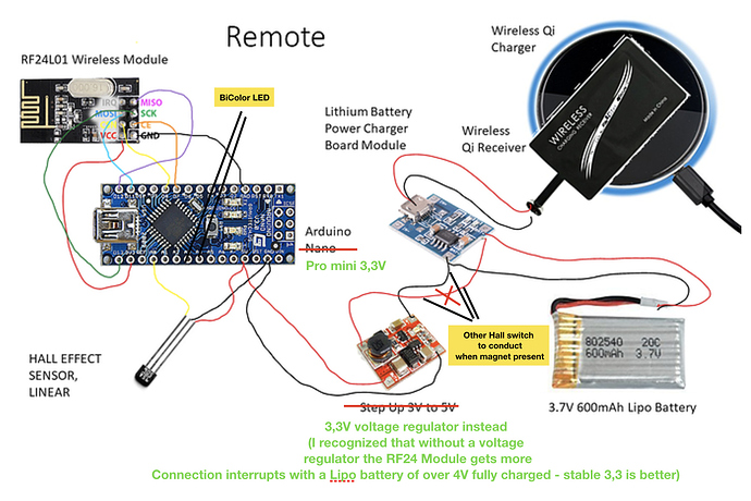
If I use your picture it would look like this:
Very good points, here are my thoughts:
- Left handed: Thats a good point… a elastic spring from the “top” would be usable for both - left and right handed. I’ll try to redesign it the next days. The most critical thing is the length of the elastic magnetholder. To get a good displacement of the magnet without plastic deformation - the free bending length of the magnetholder is important and should be long.
- I’ve never tried a hall switch but sure… as long as it is “behind” the lipo power charger board it should prevent from excessive discharge in case of a long winter.
- Seal the magnets - maybe its enough to use some paint for them.
- wireless charging is a great idea. At first I thought about a waterproof micro USB port but wireless is much better. The only thing is, that the LED’s of the Lipo charger Board are not visible and there is no indication when the charging is completed. I’ll try to integrate the wireless charging coil.
this are the “waterproof” micro USB ports - but I guess waterproof is not the waterproof we need - I ordered some and they are very smal and require very accurate installation and exact counter surfaces.
I also ordered a smal OLED display wich could be glued waterproof in the housing - maybe with a transparent/protective plastic sheet above. Since the RF modules can Communicate in both directions, you could display information directly on the remote (for example Ampere, Battery SOC and other information if the receiver can provide them with a good ESC.)
https://www.ebay.de/itm/0-91-OLED-Display-SSD1306-128x32-Blau-Turkis-oder-weis-I-C-IIC-Arduino/272901572544?hash=item3f8a3387c0:m:mrQk6KkH2WuSxye3t8TgFNQ
Hope to upload an update in some Days.
Beste Grüße,
Alexander
Very nice Alexander. We use the attached charger plug thingy. Works well. But have not tested it long term (corrosion etc).
Cheers
Hi ,
Why don’t you try ESP8266 chip like nodemcu or wemos ? It s already wifi or bluetooth .
I plan to use 2 off these, one for the board and the other for the controller.
We can power supply with 5V or 3V, Io work in 3V.
It can be programmed with lua or arduino C language. .
The most common is to use it with easy ESP as few code is needed to do lots of things.
It s really easy to make webserver with esp8266, then you can imagine to access and modify the variables easyly through web interface with a smatphone when on riverbank.
Proximity metal sensor could be a good alternative to Hall sensor a simple aluminium piece exposed to water would do the job and no rust problem like with magnet.
Some proximity sensors are rated IP69 !
