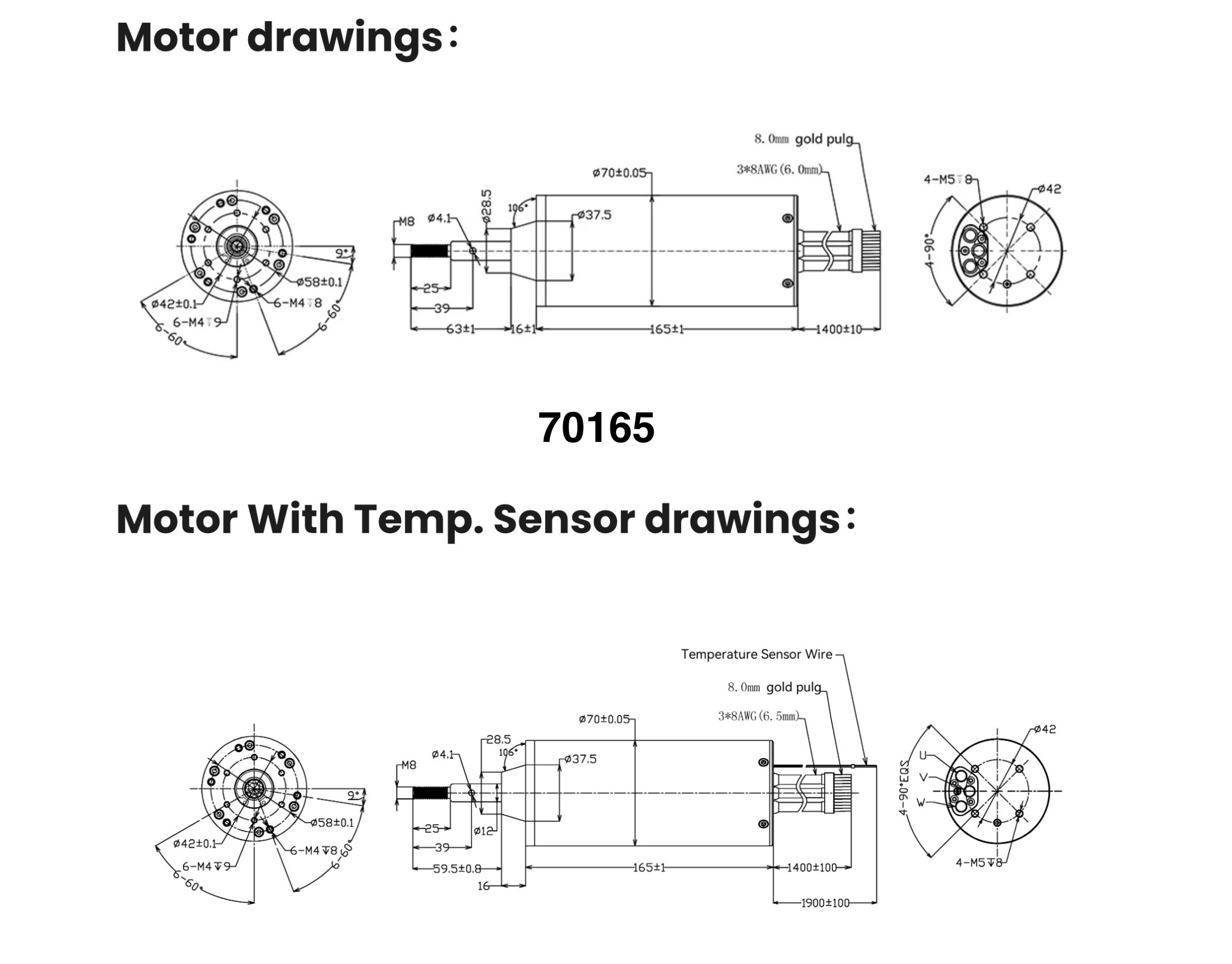
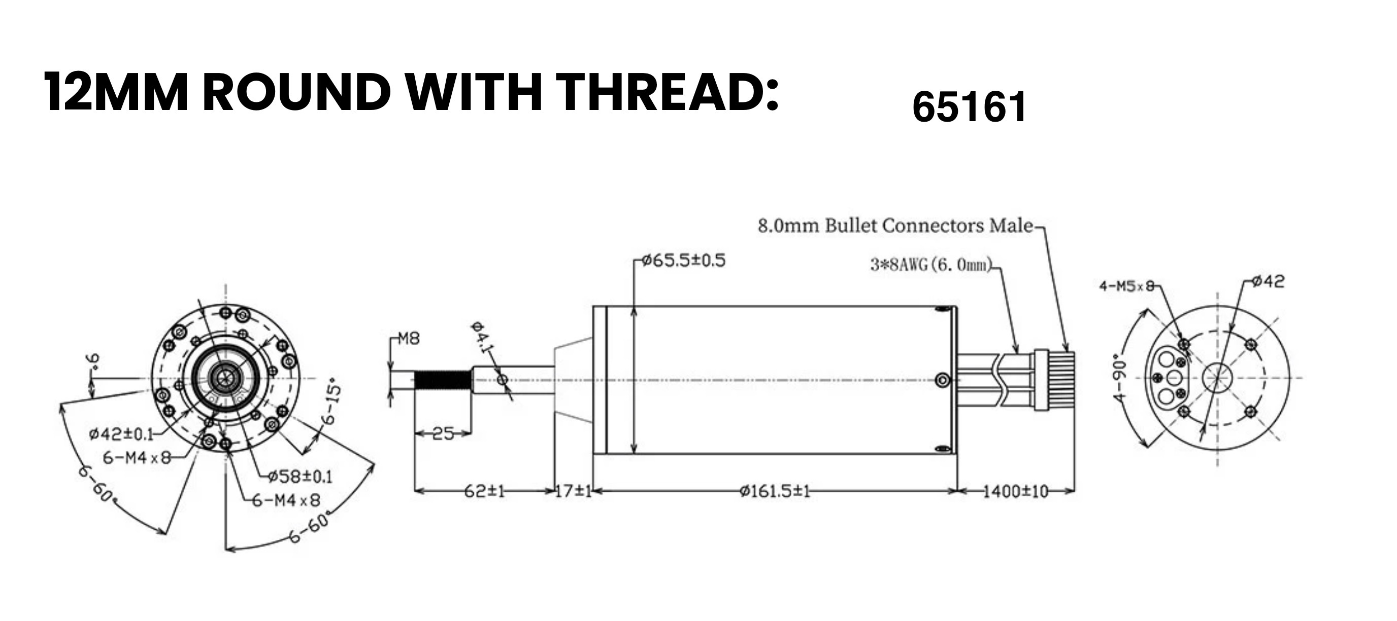
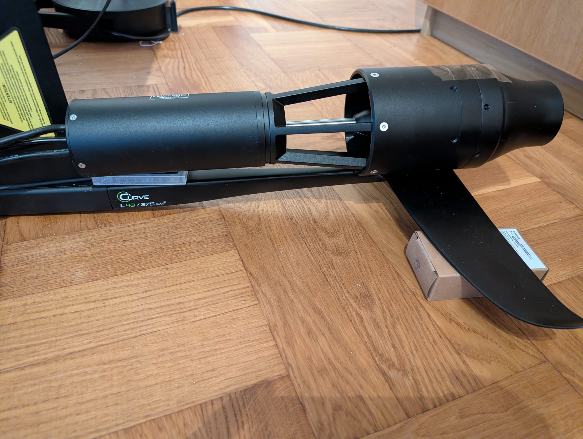
This is motor drawing from Flipsky site. Interesting the shaft dimensions are slightly different for temp sensor motor. I also include the 65161 motor for reference.
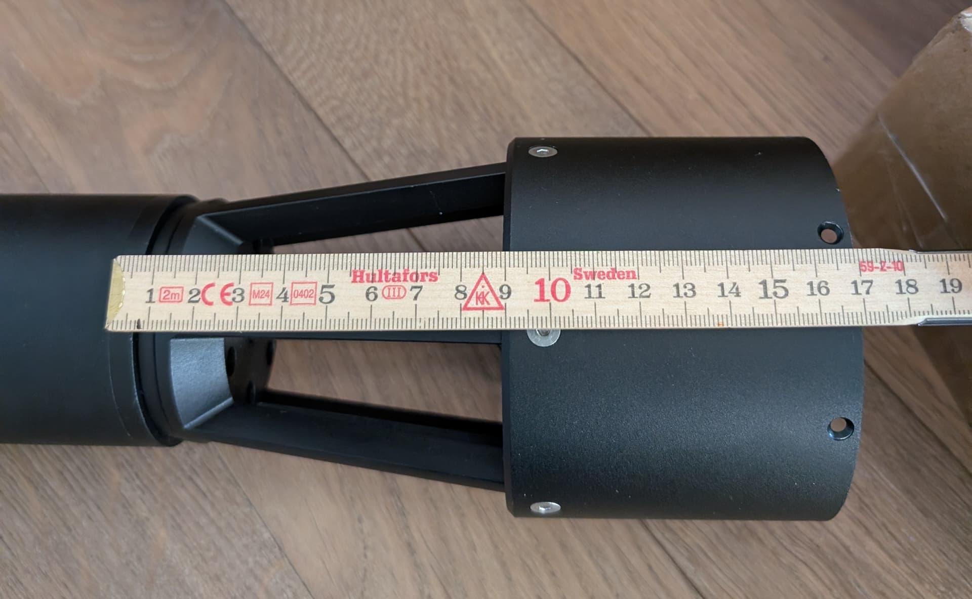
Are you able to measure the shaft? Perhaps you have reassembled and are out on the water
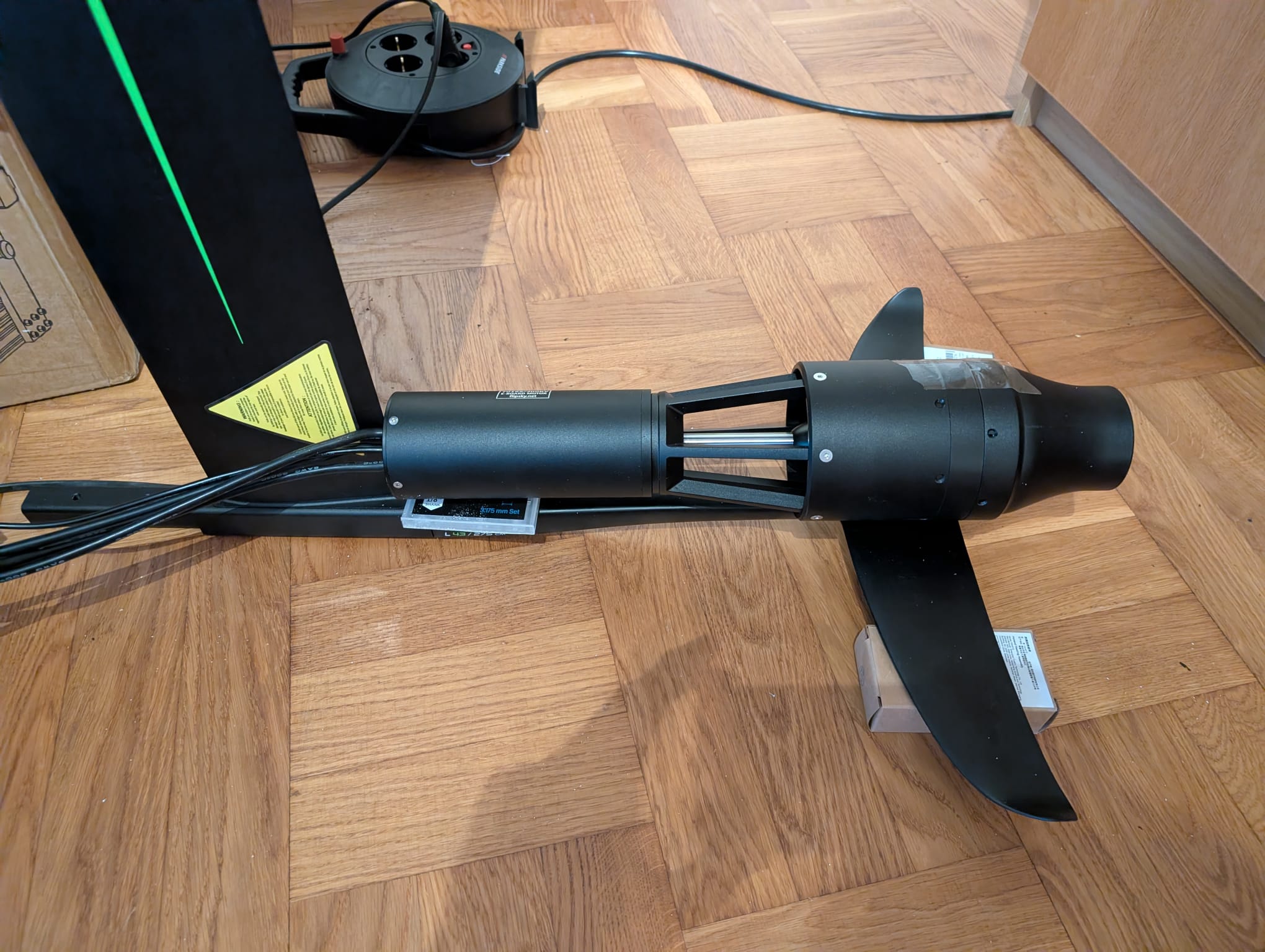
Since it is much longer and heavier than normal motor + propeller I dont think the “normal” mast-mount is enough. I am thinking of all forces that are going to pull the jet to the sides(or up/down) when I for example fall off the board is going to twist the mast and motor-mount.
I am therefore considering to mount it very low to be able to use the fuselage and stab as a support somehow.
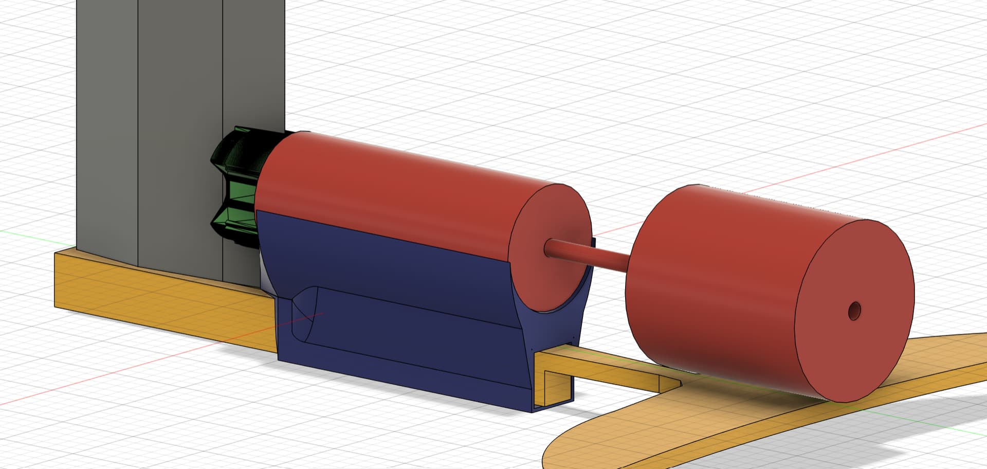
I am thinking something like this:
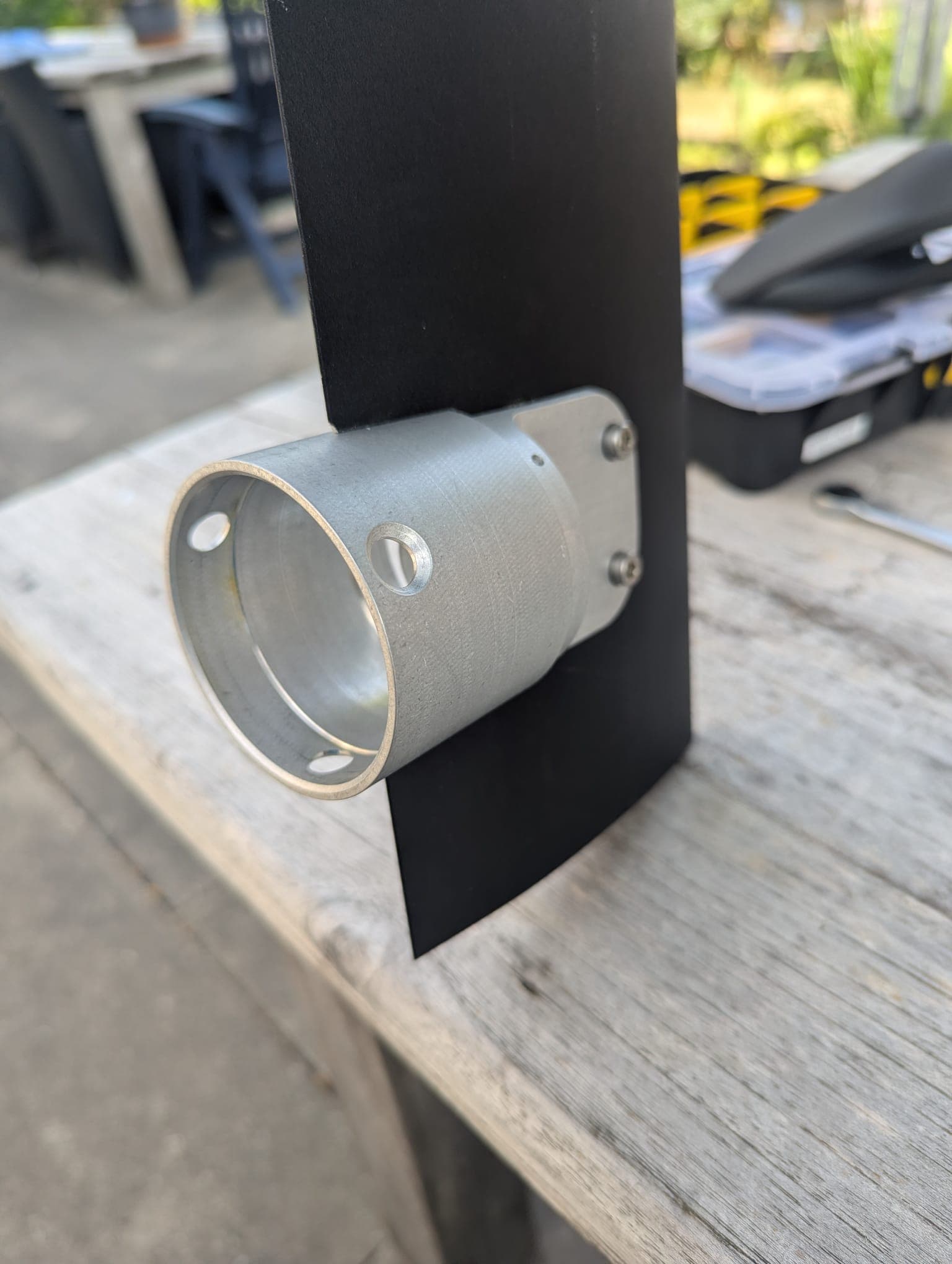
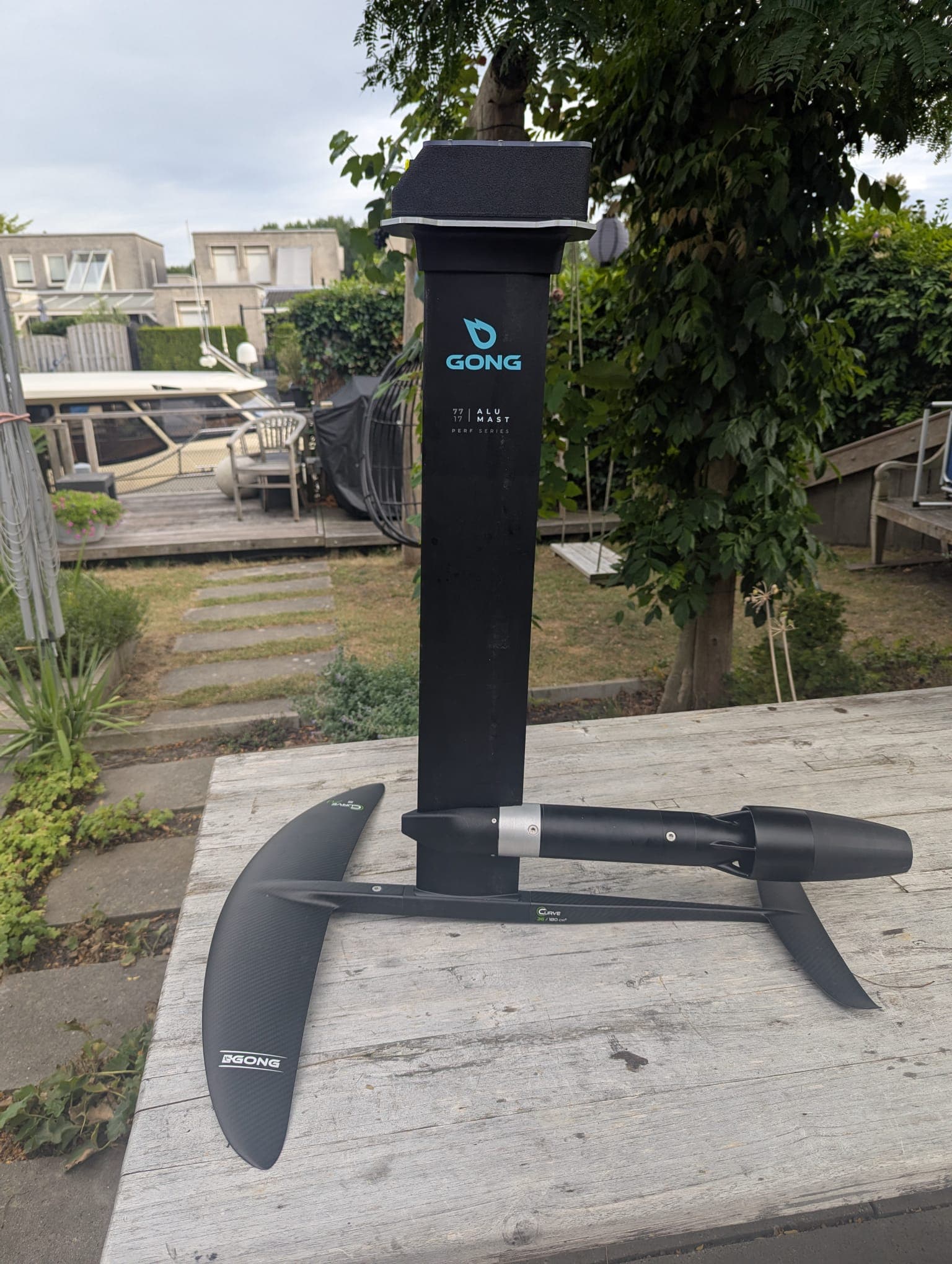
Thanks Kian for the pictures! Unfortunately I don not have the machines to make a motor mount that robust like you have.
Also the JetWave looks allot slimmer than the flipsky. The outer diameter of the flipsky jet-housing is 100mm. That is why I am worried about the twist forces if it is only supported at the mast.
The only downside of mounting the motor with support from the fuselage is that it will be harder to swap or remove the stab. But I think I can make a 3d-printed spacer with a square hole to be able to slide in/out the stab. The fuselage and the motor would practically be “one unit” tied together.
Since I dont have to care about a propeller the motor can be much closer to the fuselage and make it “one unit” compared the “tail-support” in the thingiverse model.
Jonas
Why not put the motor underneath the fuselage and jerry rig it with some (hose?) clamps.
You can even run the phase wires up to the Esc outside the mast.
It’s only for testing to see if the jet will be powerful enough.
If so, you can start making it more efficient.
Yes, that is an good idéa. But currently I am planning to make some 3d-print to fit it on top of the fuselage as the pictures above. But I like your idea to make it “temporary” without cutting the mast to start with. I will start the work on the 3d design tonight.
Mount it with a mast clamp and the rear resting on the stab.
Get the mast clamp printed properly i.e. MJF with glass-filled nylon.
Then test it and see if the jet affects the stab in any way. It actually wouldn’t surprise me if its less pitch sensitive with the jet there.
Don’t put the just under the foil. The lower the motor goes, the more front foot heavy you need to ride and then you struggle to do decent turns.
You may want to consider printing a mast clamp for your testing.
Not sure what mast you are using but the clamp I linked can be easily mounted on the mast without any alterations to the mast. It just pressure clamps on with the threaded rod to the motor.
Just clamping the motor on your fuse spacer might allow the motor to rotate due to torgue of motor.
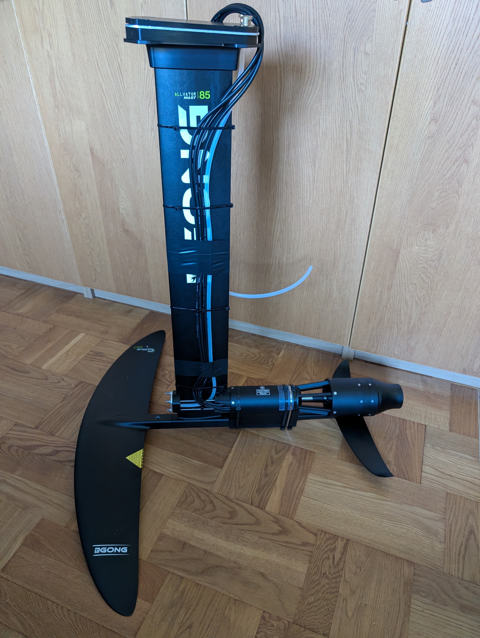
Yes i am planning to use a mast clamp aswell. The green part on the drawing is the rear part of the clamp. I did not add the threaded rods and the front part on the drawing (but i plan to use them)
The jethousing is not attached to the stab. It is about 5mm space in between in this design. It is hard to attach something to the stab because of the shape. The motor is attached to the mast with a clamp and supported and tied to the fuselage with zip ties or hose clamps(with the blue motor-support) in this first temporary mount. As Kian suggested i make it a bit quick and dirty to try it out and I can improve later.