That was just a quick mock-up to see what it looked like. There’s too much compression on a FDM 3D print in the bolt areas to really use it. I have access to big enough CNC’s to be able to cut from aluminium.
1 Like
how is the resistor (10 ohm/5 watt) used as anti spark?
Always in serial?
Here are some ideas for a DIY Foil Drive Assist:
https://foil.zone/t/new-diy-foil-drive-assist-killer-from-austria/20388/
yep, like an 5W resistor 100-1 ohms you prefer how much sparking current you’d like, 10 ohms may be good upto 100V systems i think.
You first connect the ground electrode, then the positive electrode through the resistor, wait until the capacitors charge (few sec) then plug the positive.
That amazing cable guide for the axis alu mast - would you mind sharing the model file you used?
Looks like low drag and good fit. Great build!
Thanks mate, the cable guide is created by @pablo_foil
It fits the three 12AWG wires perfectly.
Shape of the Gong V1 mast is slightly different to Axis mast, but couldn’t bother to change the file for perfect fit.
Here’s a link to pablos thread:
1 Like
Hi all,
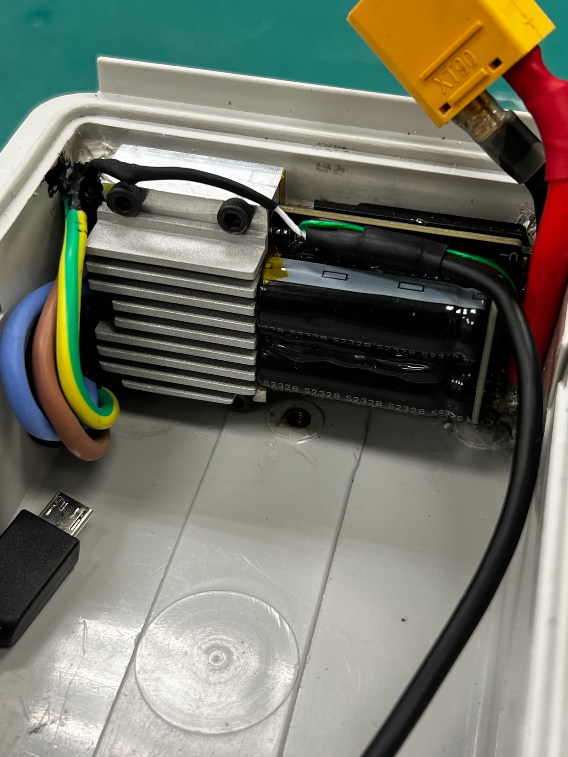
This forum has been really helpful for me and my first DIY build so thought i would share what i have come up with as a solution for ESC cooling. I am using the same Flycolor X-Cross HV3 160A as above.
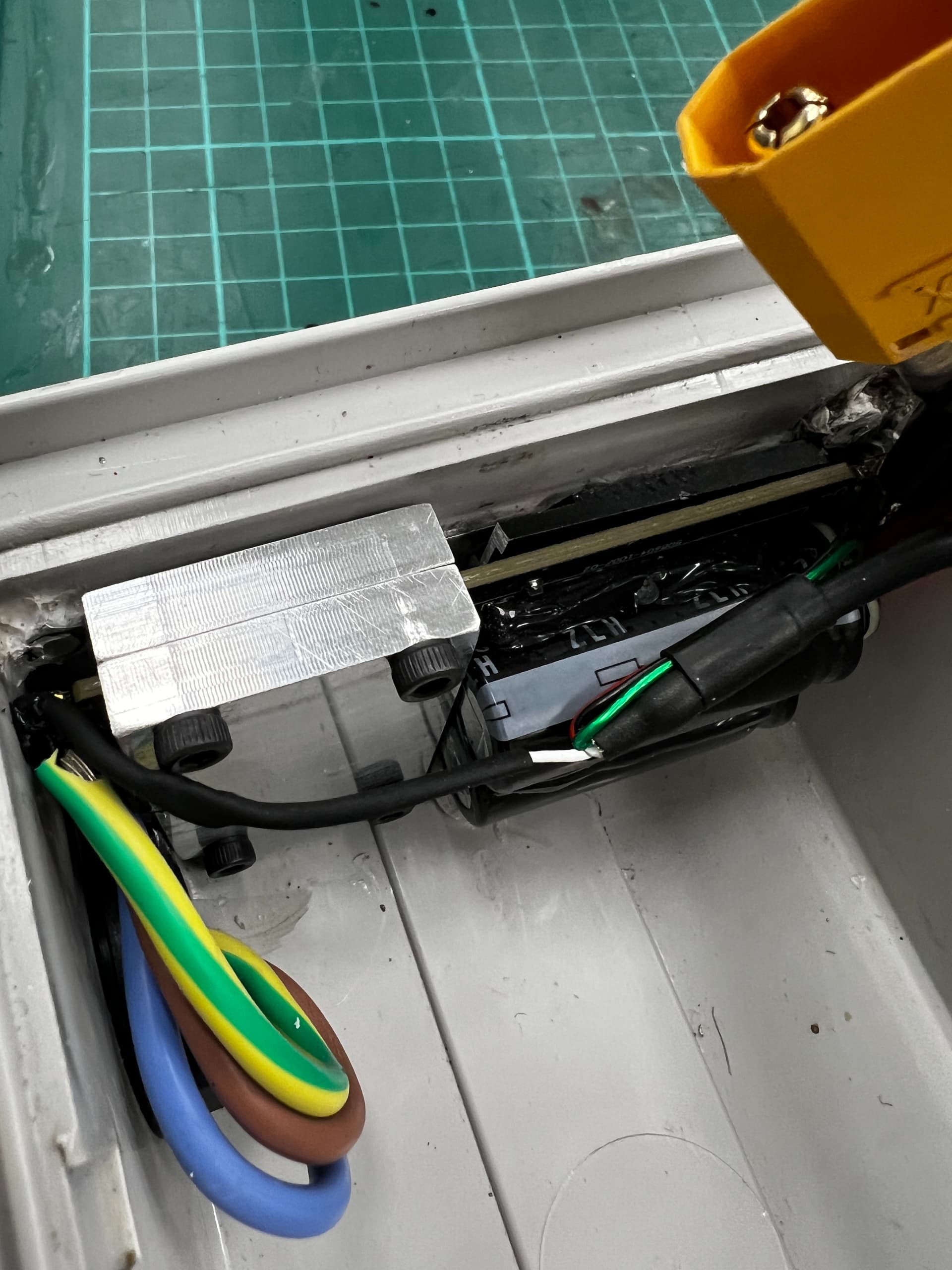
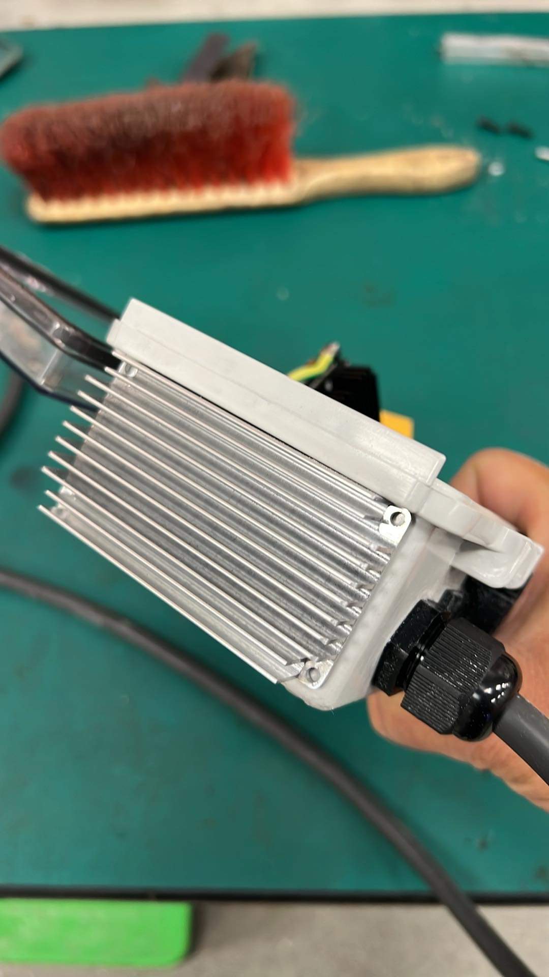
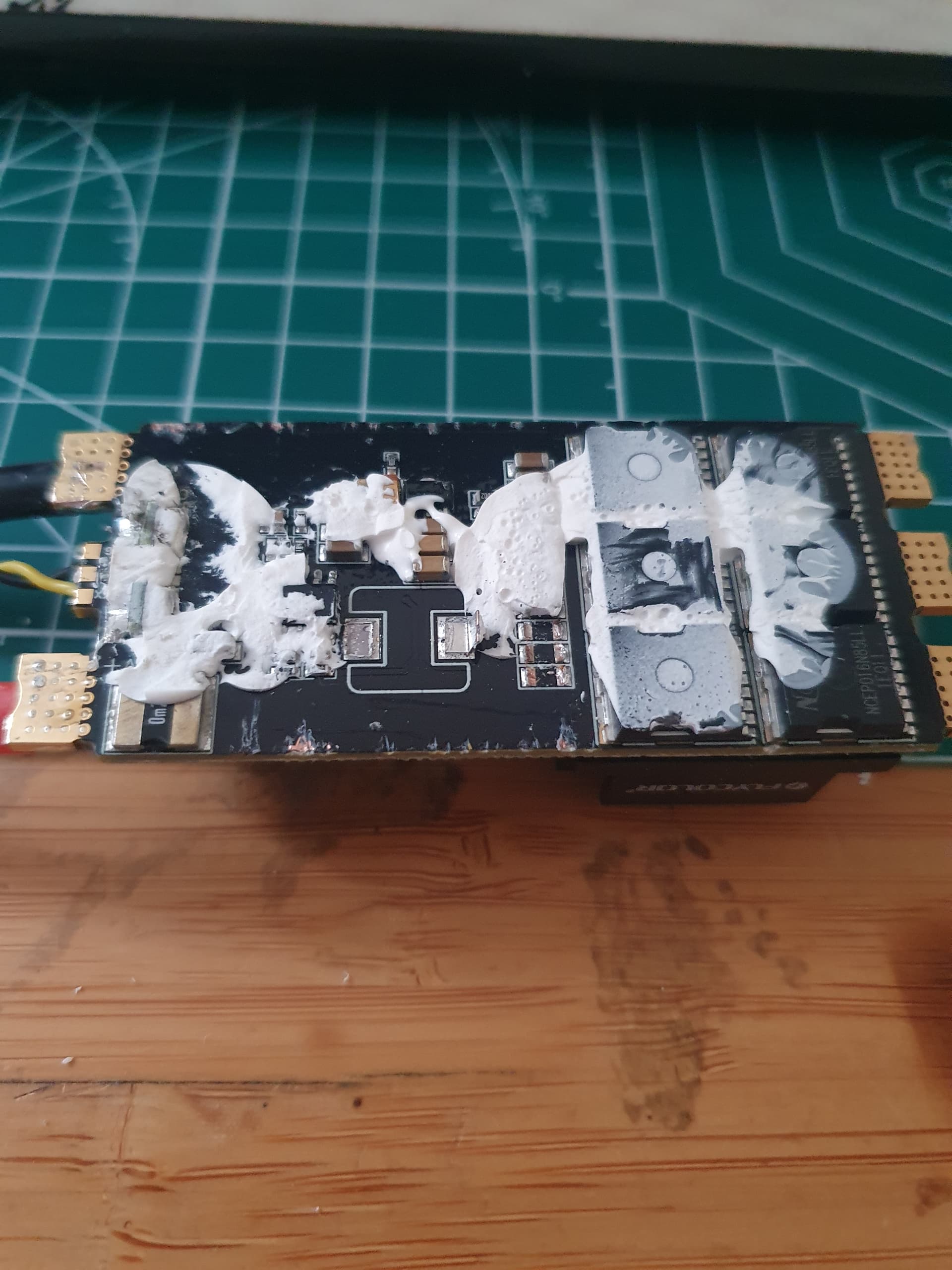
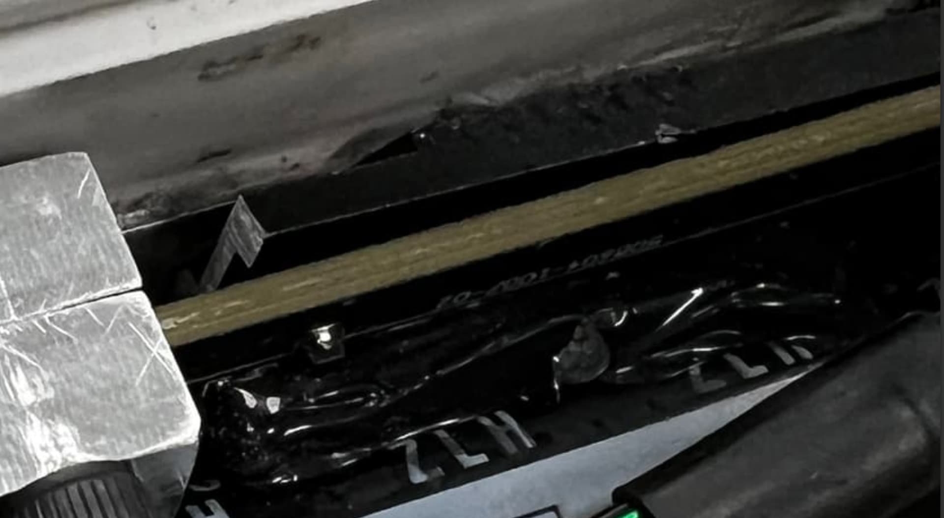
Even with an external heatsink mounted, i was finding the controller gets up to my thermal limit pretty quickly. Probably because my external heatsink was only cooling the fets on one side of the ESC. So i decided to remove the small internal heatsink and machine a clamping bracket that should pull heat from the other side to the external heatsink as well. Then i replaced the original small heatsink back on for good measure :P.
Curious if anyone has done something similar and if it has worked? Im yet to test mine.
7 Likes
Nice motor mount design! I have the same GoFoil mast type. Any chance you want to share the step / stl files for the motor mount? Thank you!
@s9tim How is your antenna laid -which orientation? I have been looking into this myself and come to the conclusion that it should be laid at 90 degrees to the length of the board (ie width-wise) - due to the torus/donut shape of radio signal. I have yet to test.
I have my antenna in the vertical position similar to the foil drive setup. Never have any signal issues unless the box goes underwater.
1 Like
I have done this for an APD ESC and it worked fantastically. I am also planning on doing the same for my X-Cross.
Did you use a heat gun to remove the existing heatsink or just brute force?
Hi @Jezza,
Nice. I’m looking forward to testing this.
I didn’t use heat, I just used a scalpel blade to gently cut through any of the heat sink cement I could access from the side, until it was easy enough to pry it off with a plastic trim tool. The small heatsink on the big capacitor side was way easier than the branded alloy cover on the other side. That one required a bit more patience and force ![]()
1 Like
Oh no! Was it just the Inductor and the small capacitors on one end that got pulled off? Those caps are easy to solder back on. The inductor has quite a fragile bottom end but hopefully if it isn’t damaged should be easy enough to solder back on.
Did you cut through as much of the cement first before trying to pry off?
Come to think of it, fishing line would work quite well at trying to slice through some of the more difficult to reach areas.
My heatsink had weird lower down sections that meant I couldn’t get under it .
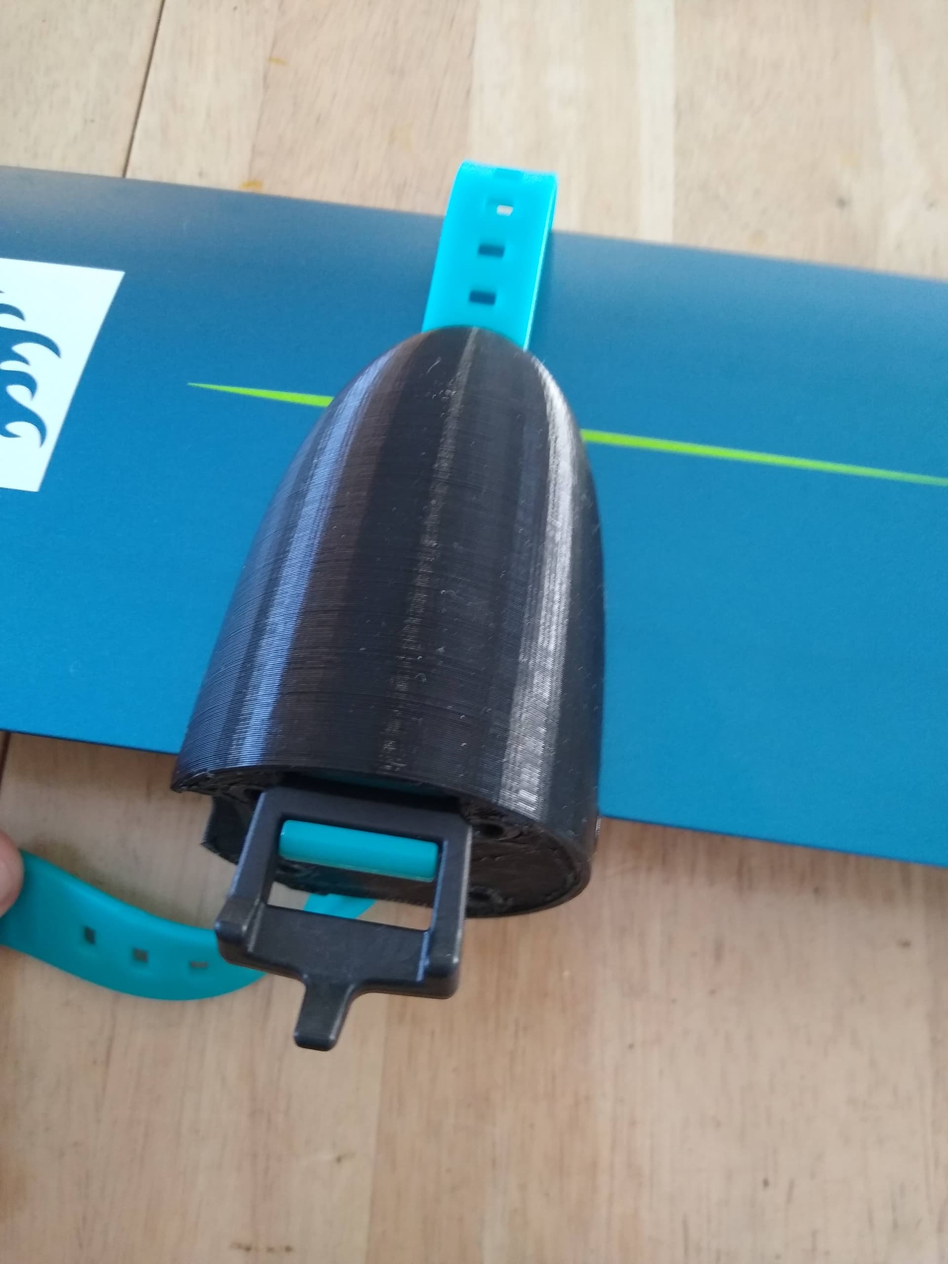
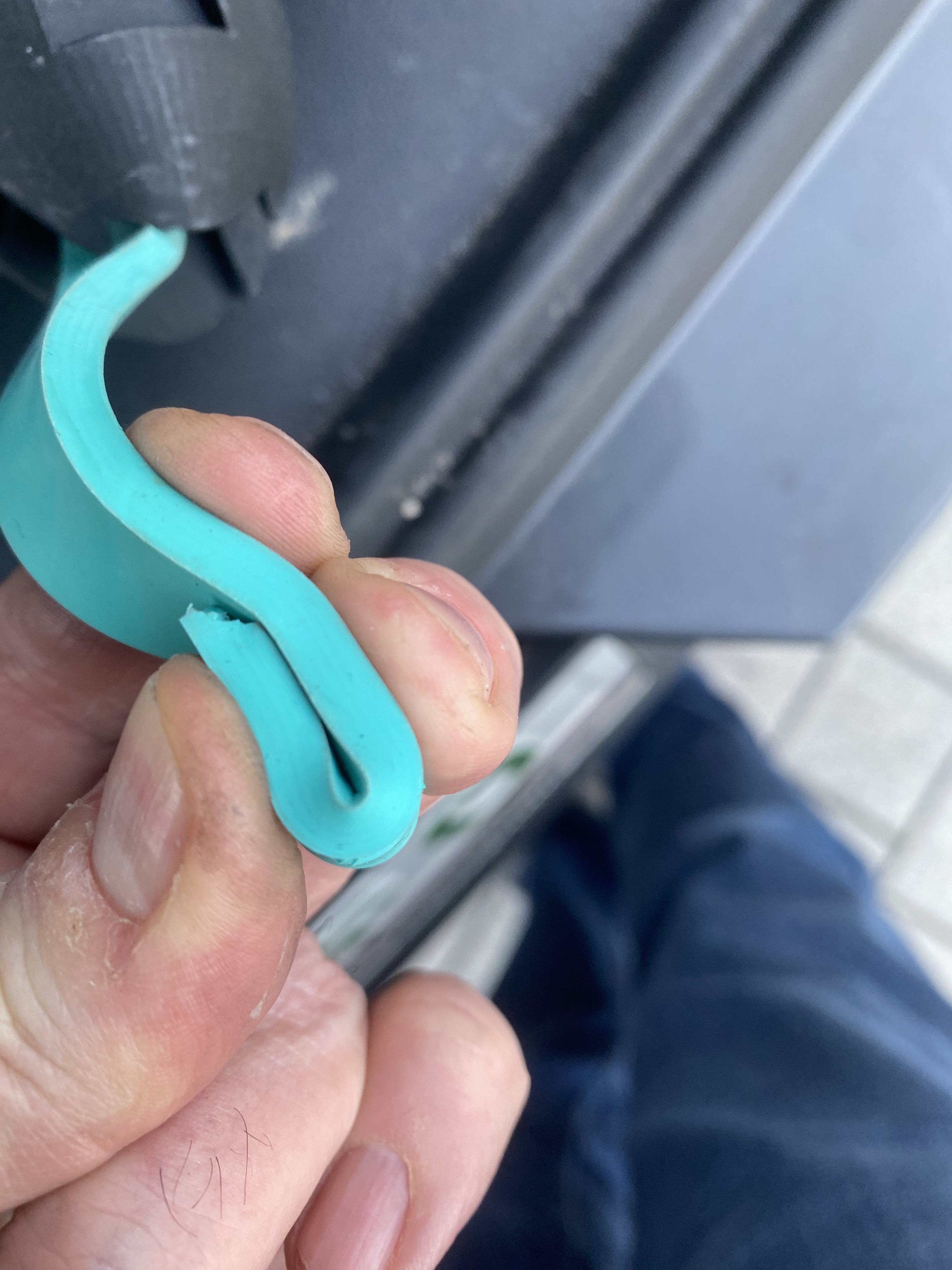
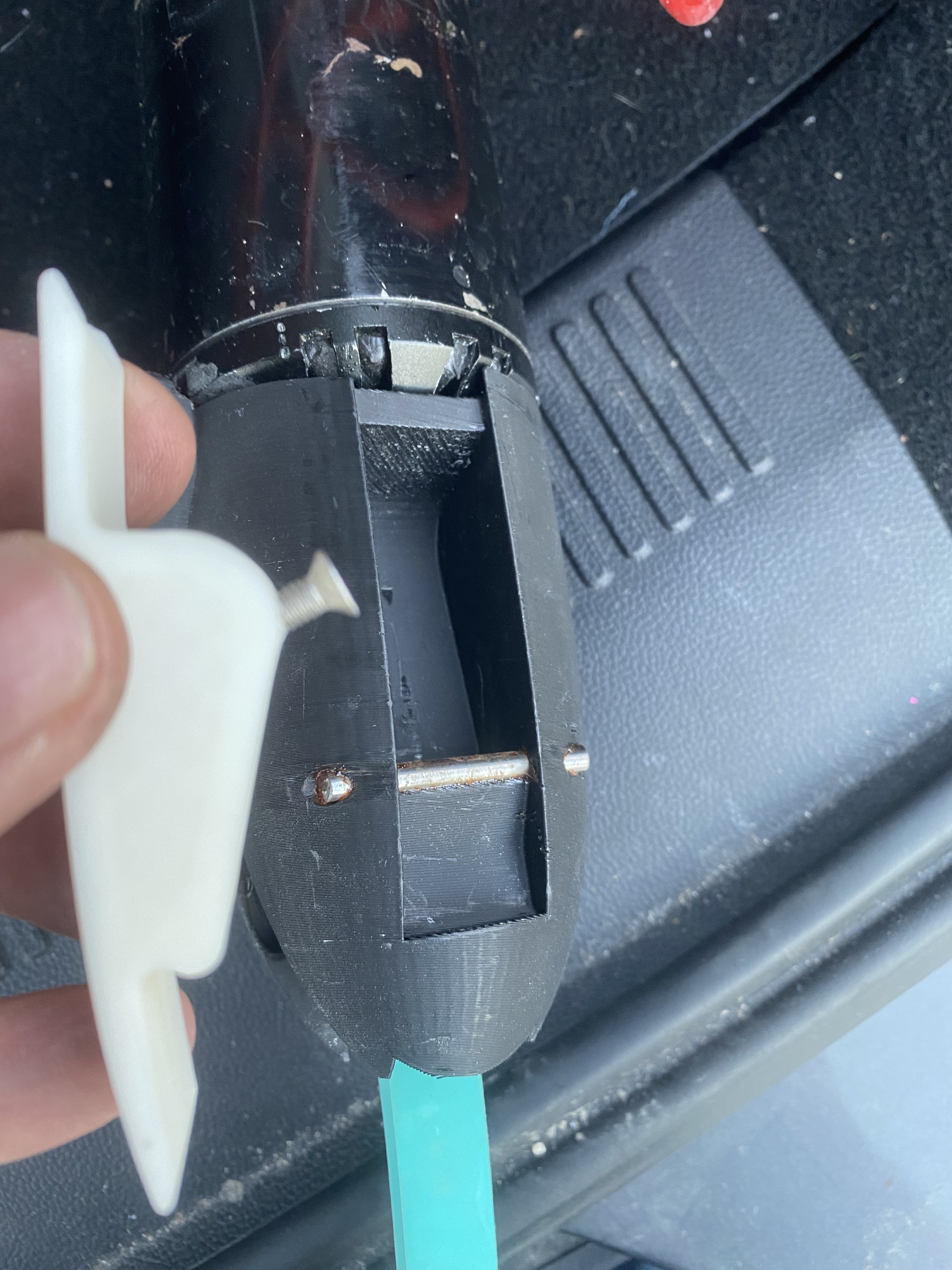
Very nice mount, thank you for sharing the design! I have a question for you or anyone who uses the mount, how do you reliably fasten the strap to the side opposite of the lever/pivot mechanism? I cut down the buckle of my strap and jammed it in there. It seems to do the job, but I am worried it could slip sideways and fail. I am considering printing a wedge to lock everything in place, but I am curious what other people are doing.
3 Likes
Clever design with the machined parts!
That black part is to cool the inductor or just as a spacer?
And you put another black spacer between the outside heatsink and inside?
A note regarding internal heatsink: No need for the actual radiator with fins inside an enclosure because no air moving. Only mass of the aluminum matters.
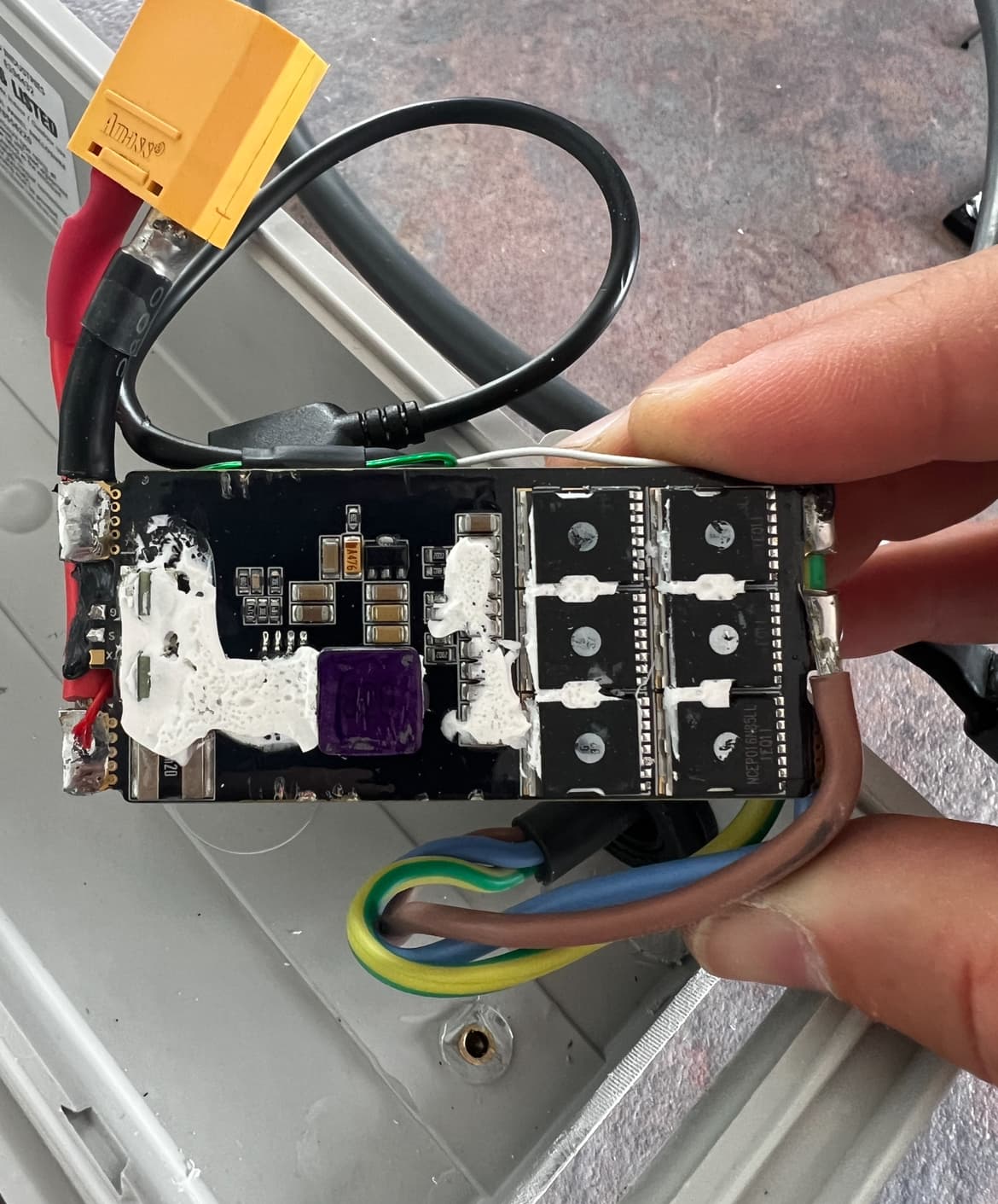
That ESC has a weird design…it’s transistors are actually equally distributed across the sides. So unless you cool both sides, will be bad cooling.
And why is the heatsink that long?? To cool the inductor? What is the role of this inductor and since when and inductor gets cooled?
@lishine Thanks.
The black part is actually the original alloy branded cover which acts as a heat sink on the other side. It has just been cut shorter as you say to act as a spacer, plus transfer any heat accumulating in the inductor. I am assuming there is some inductor cooling required because the original cover had thermal paste in a very specific recess in that part of the cover - designed to fit around the inductor. .
I know that the internal heat sink will not be that effective given that there is no internal airflow but i thought it wouldn’t hurt to put it back on since it requires no additional space.
1 Like
Thanks for answering.
How did you do the connection to the outside aluminum heatsink?