This post describes how I built an assist kit for hydrofoiling using a waterproofed outrunner. Probably there are better ways, but this worked for me. So far I’ve been 5 times in the water without issues. Everything still works like the first day
Specs at a glance:
- 6374 170 kV motor
- 6S, 16Ah battery (P42A) (350Wh)
- 150A flyer esc
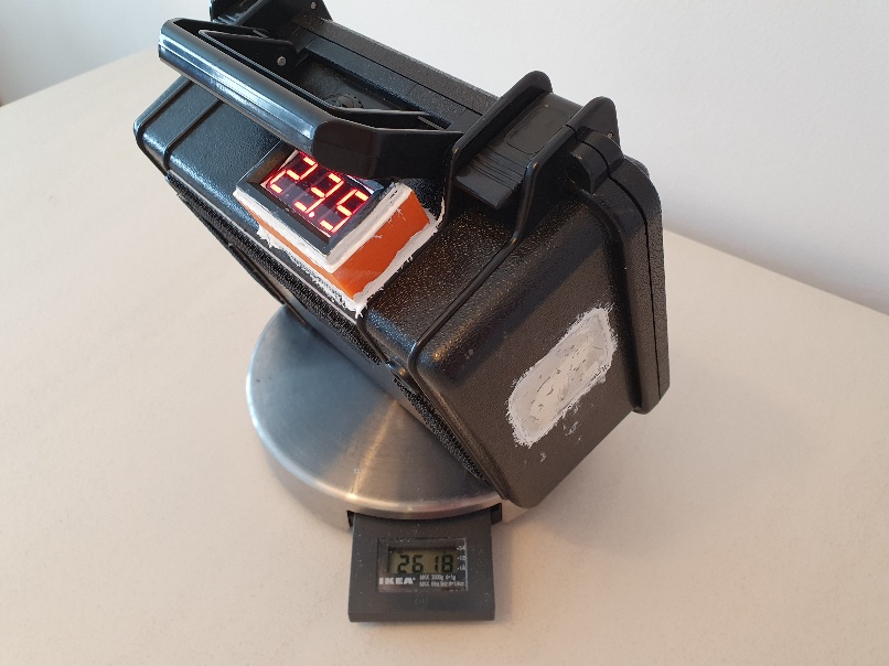
- 3.75 kg total weight
- Speed: at least 18 kph with a Gong veloce 1900cm^2
which is more than enough as an assist to start flying. Also, no cooling in the box + big prop also means it will overhead if used continuously
DISCLAIMER: This is not a tutorial to build the device I show in the pictures. The goal of this post is to help those who wish to build a DIY device of this type but get confused searching through the forum and want to have all the info in a single place. Having said that, this is a dangerous hobby. You have an exposed propeller with 2000W of power than can easily chop off a finger if you fall over it (see Cut off thumb from 10y old ) or worse . On top of it, you have a battery that could easily be exposed to water, possibly leading to fire/explosion since it’s contained in a closed box. If you build something following what you read here, I take no responsibility for the damage you do to you/others or property while building or operating a device based on what you read on this post. You take full responsibility for the consequences.
To the experienced guys in the forum, please add your suggestion and I’ll add them to this post.
Waterproofing a 6374 motor:
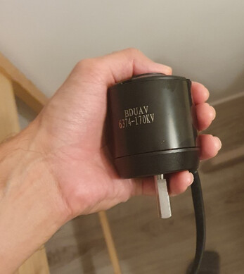
The kV of the motor I got is a bit higher than I’d have liked, but to learn how to waterproof should be ok (also it’s meant to be used with 6S, so it should be ok). The one I got is 170kV for 50 euros, so can’t really complain. I tested the speed without load to confirm the kV ( around 4000 rpm @6S)
Steps
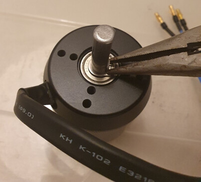
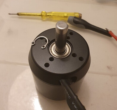
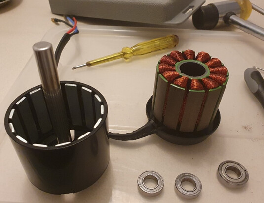
Step 1: Removing the snap ring. I didn’t have a special tool, but the one in the pic did just fine.
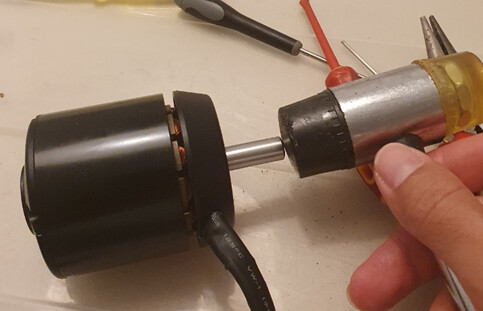
Step 2: Removing the Rotor. I used a soft hammer, I also had to apply some force since the magnets will try to keep the rotor in place. A piece of fabric between my hand and the motor was used in case it snapped back in place, otherwise it’d get my skin with painful results.
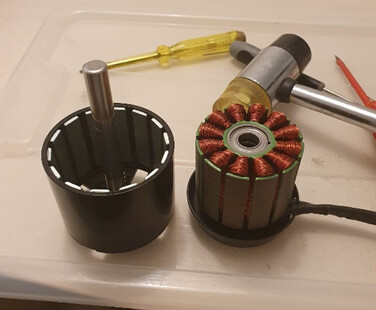
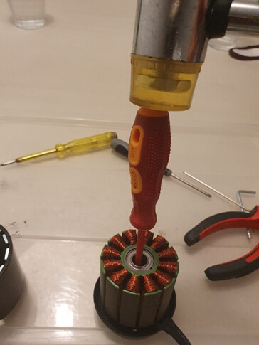
Step 3: Removing the bearings: Since I didnt want to keep the original ones, I didn’t really bother being gentle… I managed to save 2 of them , but one of the small ones was damaged when I hit the bearing cage. This motor has one 22X10X6mm bearing in the cables side and two 19X10X5mm bearings on the other side. The inox versions for them are 5-6 eur each (a lot if you consider that the whole motor was 45 eur !)
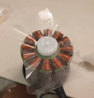
Step 4: Waterproofing the stator to protect the regions where we don’t want the resin to enter. The easiet way is to create an epoxy cylinder that fills all the voids, in the stator, all the way to (almost) the base of the motor. In my case, I decided to fill all the way to the base, to make the temporary container for the epoxy easier to seal. (Alternatively I could have created a pool of wax in the bottom and then melt it after the resin is set or simply remove the stator, as it was done in other threads)
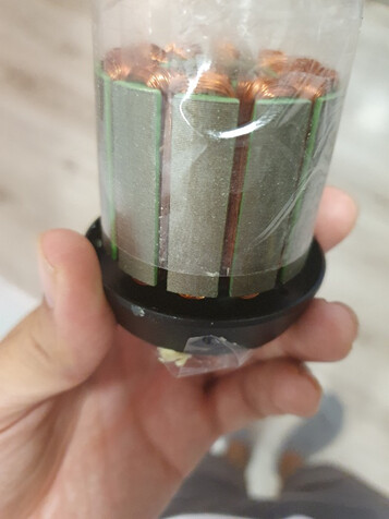
4.1 In any case, we’d be unlikely to get a tube with exactly the same diameter of the stator, so I just created my own… with adhesive tape! . The trick here is to lay the tape on the non-sticky side and wrap the stator like this. This way, I got a sleeve that can be moved (slided) downwards since it’s not glued to the stator.
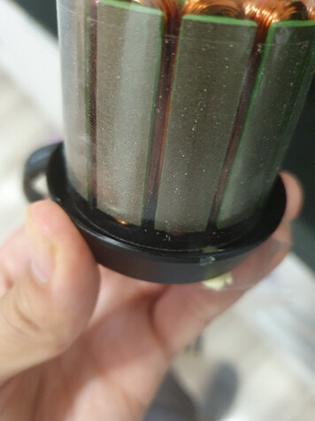
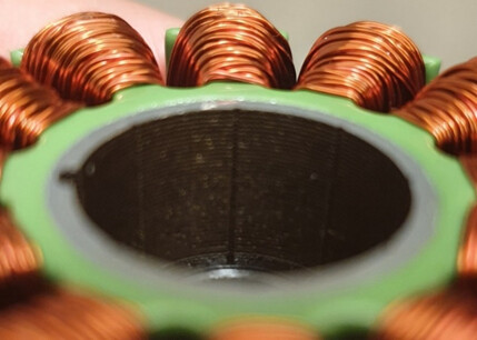
4.2 Applyng also some wax on the top part to preserve the bearings housing clean. (I noticed that the bearings lie directly agains the iron stator, I’ll have to add grease or something to prevent water from entering here, otherwise I suppose the bearings will be impossible to remove in the future when this gets rusty) I did it this way (wax only) and it was not enough since resin leaked inside. Next time I’ll also add grease to prevent resin from entering via capillarity when applying the resin
In my case I sticked a candle inside and then improved the seal by melting some more wax around, especially in the gap you can see on the left. I took special care protect the parts from wax where epoxy will later bond to, to guarantee a good bonding later.
4.3 Sealing the holes left in the bottom. I Used wax for regions where the cables are located and also where the adhesive tap sleeve touches the base. For the screws , I simple screwed 4mm screws with some grease to prevent the epoxy from binding to them. And voila, ready to be filled with epoxy
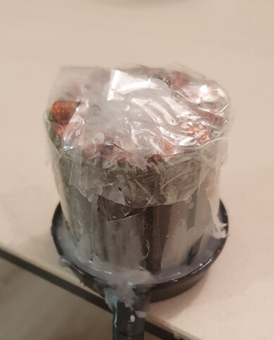
Step 4.4 Filling it up! To make sure air was able to escape, I tilted a bit the statator as I was filling it. This way one of the air colums was free of epoxy and air found its way out through it.
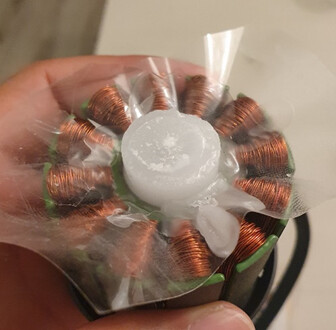
IMPORTANT: FAST CURING EPOXY IS A NO GO! There is some serious thickness in some places, so using fast fiberglassing resin might lead to high temperatures and smoke. As for how much, In my case, I needed around 50 grams of epoxy to fill everything as shown below.
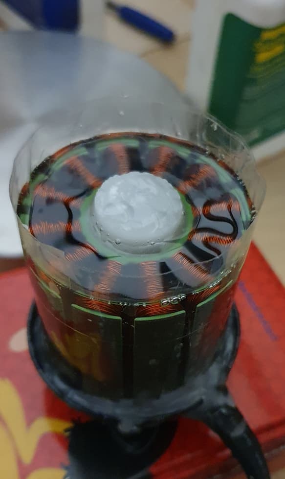
Step 4.5 : removing wax and tape and done! Since I used a very thin epoxy, by capillarity the resin was able to fill the very thin gap left between the tape and the iron stator, so no need to paint it afterwards. Doesn’t it look beautiful? Just needs some sanding on the top and it’s ready.
NOTE: I did not add grease in the bearing housing on the top, so some resin leaked through the wax plug. I had to remove it with a knife, task that took a while.
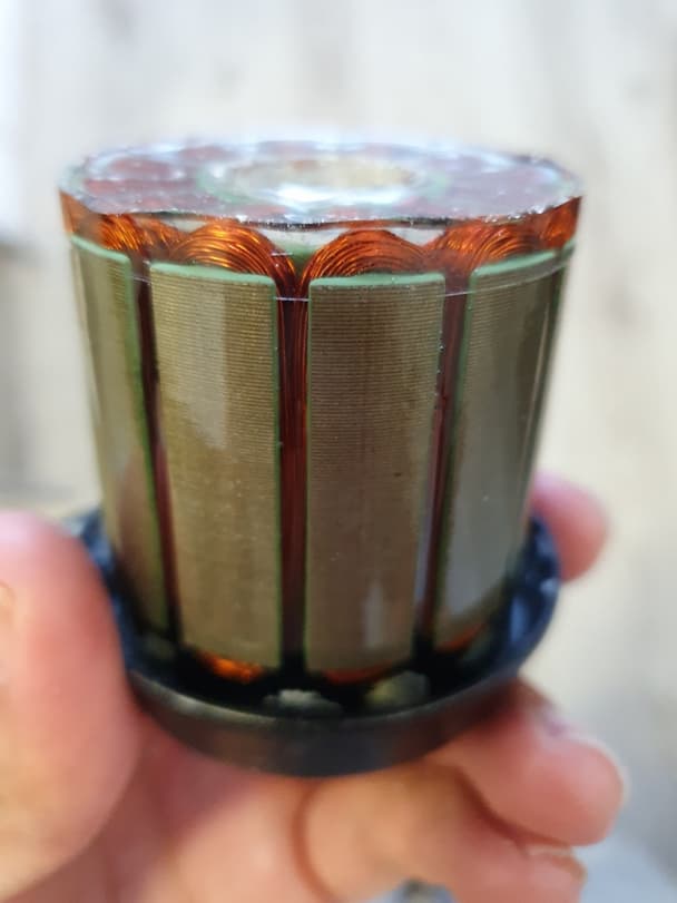
Step 5: for the rotor, I simply prepared a bit of epoxy and paint the magnets so that there’s no exposed surface. Then I cut the extra length of the axle and the motor was ready!
Quick BOM:
Motor: 45 eur
Bearings : 18 eur
Epoxy: 100 grams <10 eur
Electronics:
ESC: Flycolor 150A boat esc. It has a water inlet but havent used it.
RX/TX : cheap eskate remote, so that I don’t feel bad if it dies. I bough a soap dispenser and placed the TX inside.
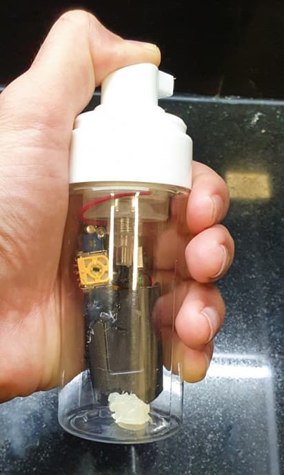
To mount it on the paddle, I place it almost in the top, with its axis parallel to the paddle. The position of the analog “button” is such that I can press it with my middle finger while I’m still paddling. I find this configuration optimal since it does not force me to have a fixed position in my lower hand, which would happen if I was using a trigger remote.
BOM:
ESC : 52 eur
RX+TX= 28 eur
Soap dispenser = 2 eur
Battery:
Made from 6s4p p42a. I have no experience welding cells so I paid a local guy to weld it from me. It uses a Daly 6S 40A BMS for charging only and a 150A fuse as a protection when discharging. Nothing fancy about it. The 40A BMS output can be used to power the RX, so that if the BMS detects a low cell/high temp, power in the RX is lost and motor turns off.
BOM:
Cells + shipping: 150 eur
Manufacturing (including cable, wrap, etc) :100 eur
BMS : 19 eur.
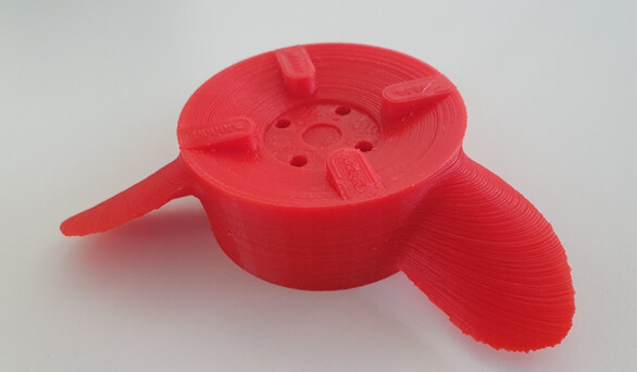
Propeller:
For the propeller, I simply took the propeller created by https://www.wageningen-b-series-propeller.com/ using as input a 175mm prop, made of plastic, at 1800W @ 10knots and 2600rpm.
(Regarding the target rpm, I had to go so low because: 1: the max mechanical power of these motors is around 70% of the free spinning rpm and 2: the battery pack is small, so the voltage drops a lot when we push the pack to 100A. I’ll open a separate thread to discuss this. )
Since the website creates props with a hub dia of 64, I had to either select the expert settings or scale it down a bit to 63/64, I just went for scaling. Then I just subtracted the parts of the motor casing to get a perfect fit with my motor. Note: the prop shown in the pic is 135mm, which was too small. I am now using a 175 mm one. Pushes nicely but consumption is horrible. I was using it for a minute uninterrumpted, and and bag touching the esc partially melting, suggesting I’ll need to either reduce the power or add water cooling.
I still have to find the sweet spot, to get a better efficiency (albeit with less mechanical power) . In any case, a prop takes a couple of hours to print, so I’ll print a bunch and test them later in a single day.
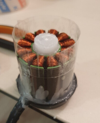
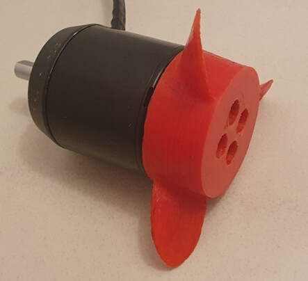
Motor shown before cutting the shaft using a dremel
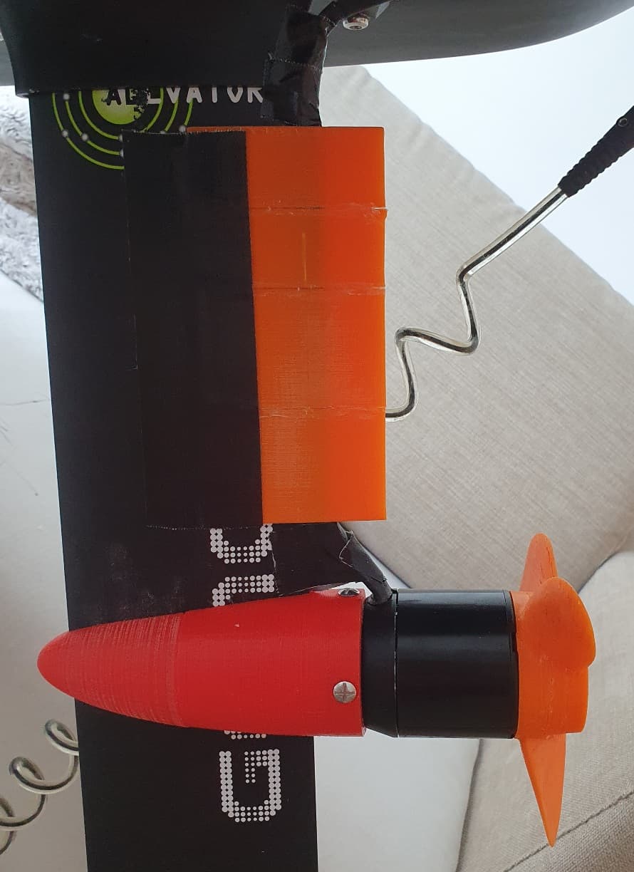
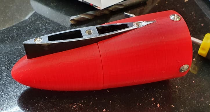
Motor pod:
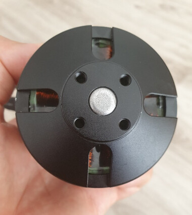
For the motor pod, the easiest way is to print it in 3 parts, as it was done by most users here. In my case I embedded the nuts inside the printed part: In the cad, I leave a hole with the shape of the nut. Then during the print, just before the printer is about to print the layer that covers the hole, I paused the print, added the nuts, and resumed printing. I used embedded nuts in both the pod and the motor support.

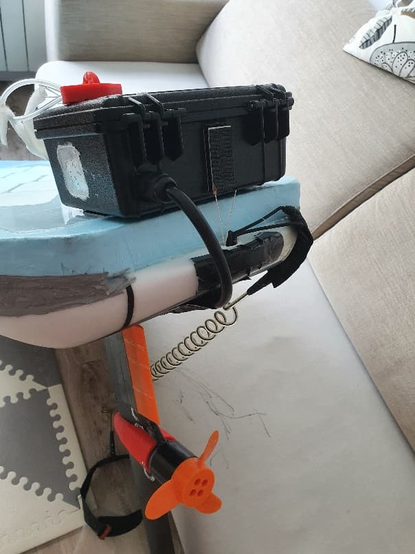
The mounted pod:
Waterproof box:
Sealing the box
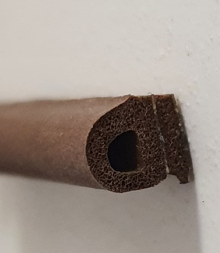
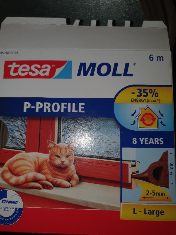
my board is only 75 l, so when I sit on the board the box is fully submerged. Then I had to make sure the box is 100% waterproof. A quick test in the kitchen sink using the original seal ended up with several ml of water inside the box. To fix this, I had to replace the seal with window/door seal. Now not a single drop enters in the box. This was the only modification needed for the box.
BOM:
box : 17 eur
window seal : 6 eur
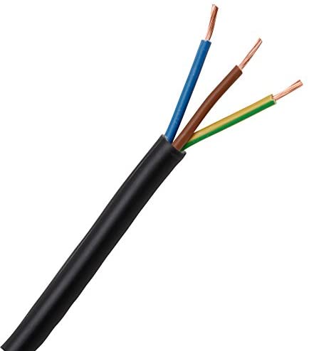
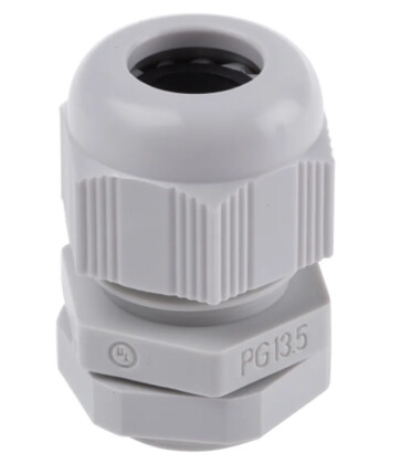
Cable inlet:
The next step is the cable inlet. I simply drilled a hole and use one of these.
Kill switch:

The RX is powered through a reed switch. This switch is kept closed using a magnet attached to a leash. In order to keep this magnet in place, I added two flat magnets inside the box. I had make sure the inner magnets do not active the switch. Also, I had to place the switch off-centered from the outer magnet, otherwise the magnetic vectors would have no components that can activate the switch.

Note that the ESC will take 1 second to turn off the motor if the rx dies, so it’s not a perfect solution. It’d be better to use the reed switch signal to change the signal we send to the esc, but that would require adding an Arduino in between, increasing the complexity.
That’s pretty much it. I have the files for the propeller and motor pod in freecad. I’ll upload them when I find a way to attach them. Freecad is free and works really well. After finishing your design, simply go to mesh → create mesh and then export the stl mesh.
FreeCAD files:
mast cable guide : hydrodynamic cable guide for gong hydrofoil mast V1 by pabloartz - Thingiverse
prop: Propeller for low power efoil (assist) by pabloartz - Thingiverse
motor pod: Motor pod for low power efoil with 6374 motor by pabloartz - Thingiverse
To improve cooling I have added heatsink for the ESC (see posts below)