One caveat before any of it: I know nothing about building a foil. I’ve never laid one up, I’ve never printed a mold, and I’ve only ridden the ones I bought. So read everything below as a modelling exercise by someone who’s about to find out how wrong he is, not advice from someone who’s done it. That’s partly why I’m posting it: plenty of people here have actually built these things, and I’d rather be corrected now than after the resin’s gone off.
This started as a side quest. The folding prop and the blade generator are the original project, but to size a prop you really need a drag curve, and for a drag curve you need a foil, and nine hours on a plane with a laptop open turned “how much drag does my foil make” into something bigger than I meant it to be. It’s near enough done that I’d rather show it than sit on it.

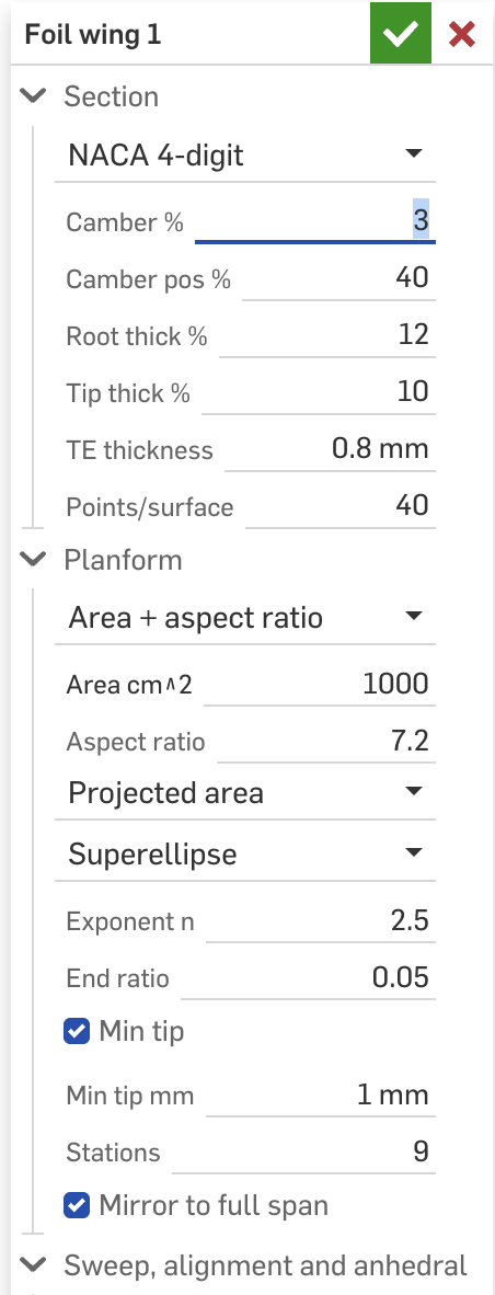
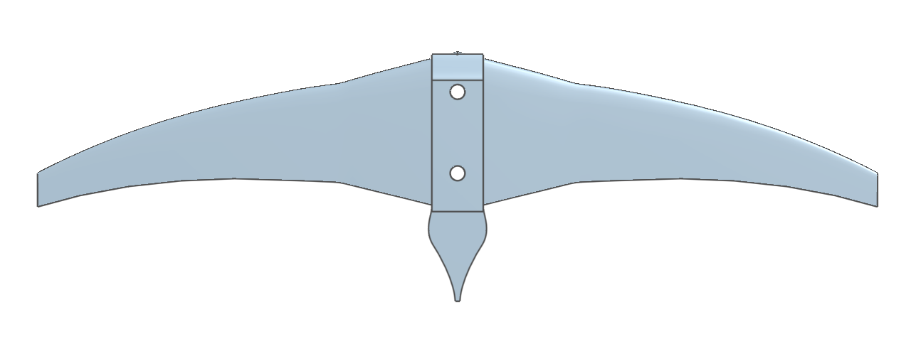
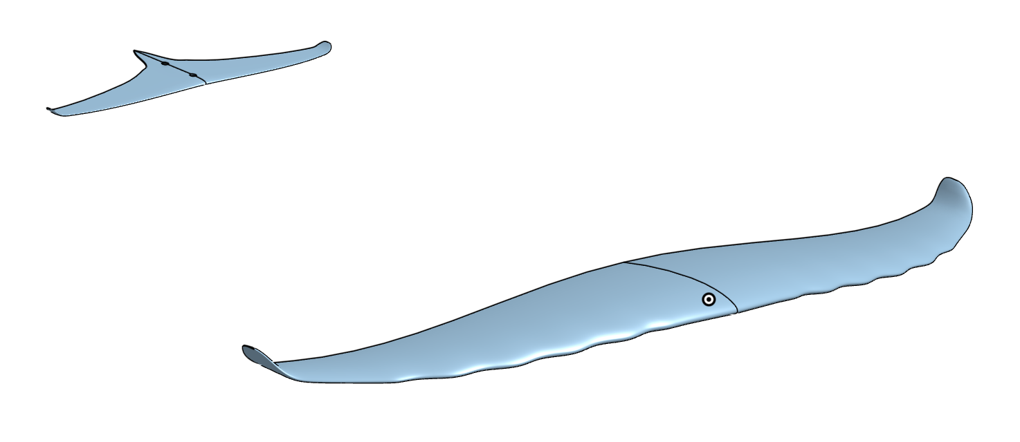
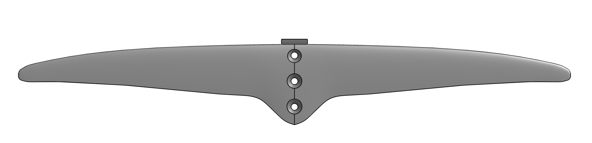
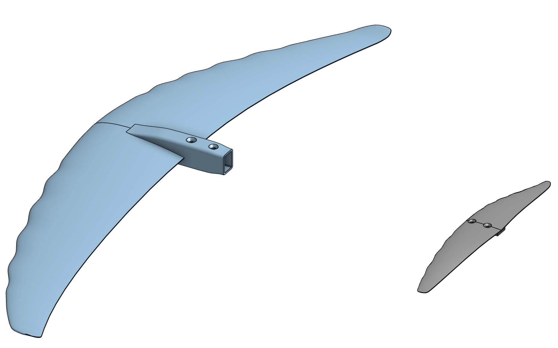
It’s one Feature Studio with six custom features, used in order in a Part Studio. Wing: give it area and aspect ratio, section, sweep, tip drop, washout, incidence, and it solves the planform to hit the area. Stab: same, placed by arm, optionally linked to the wing as a fraction of its area, and it carries the mount pad, tail fairing and bolt pattern, all pinned to the stab pivot so any stab fits the same fuselage. Performance: no geometry, a speed sweep, lifting line for wing and stab, trim, stall, static margin, drag including mast, pod and fuselage, root bending, and with the propulsion group on, the same B-series maths as the blade generator: rpm, throttle, amps, Wh/km, range, top speed, and what the thrust line does to trim. Mast, tapered and thickened toward the plate with a fillet into it and an optional pod. Fuselage, a round tube that spigots into the wing and seats on the stab’s pad. Then the mold feature.
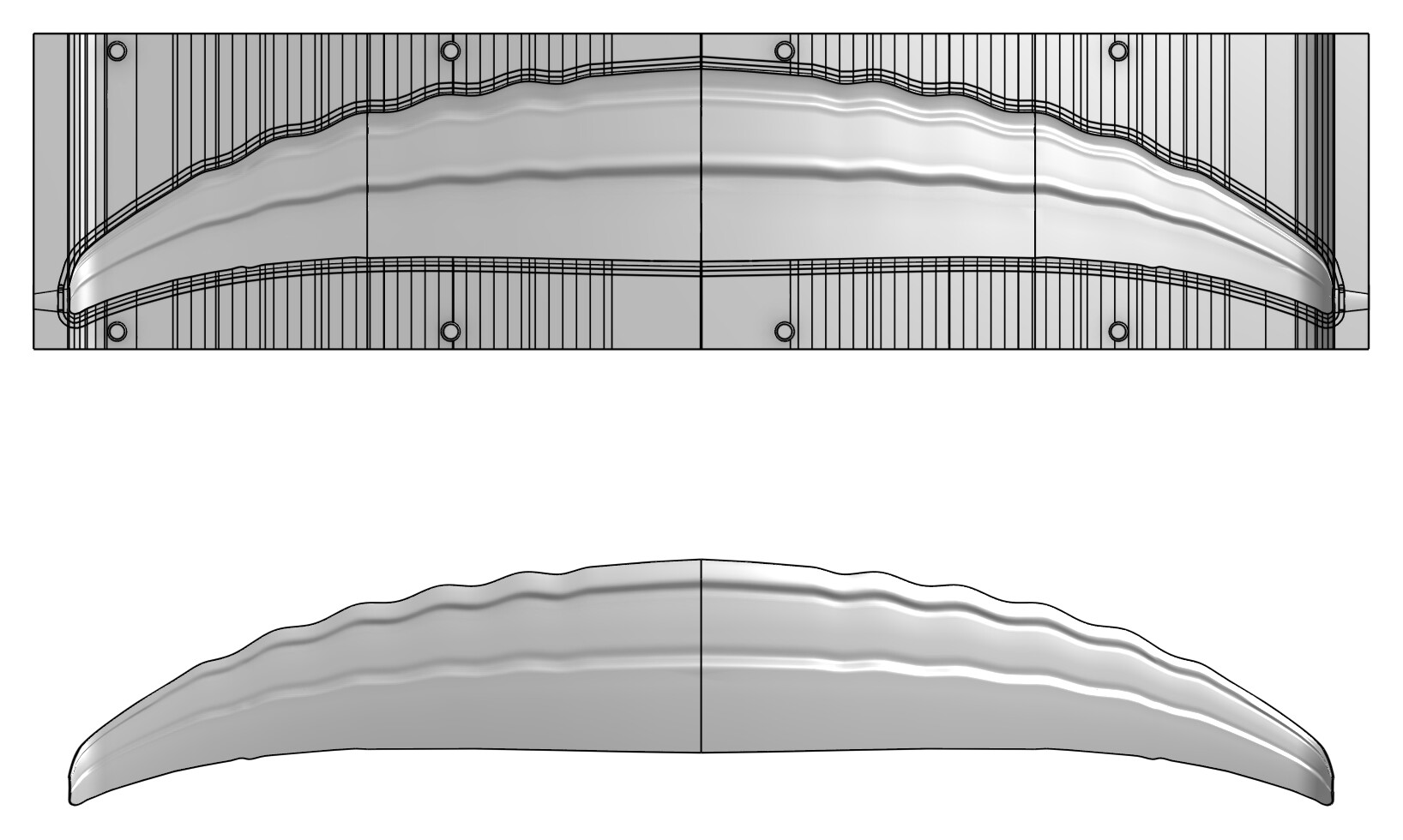
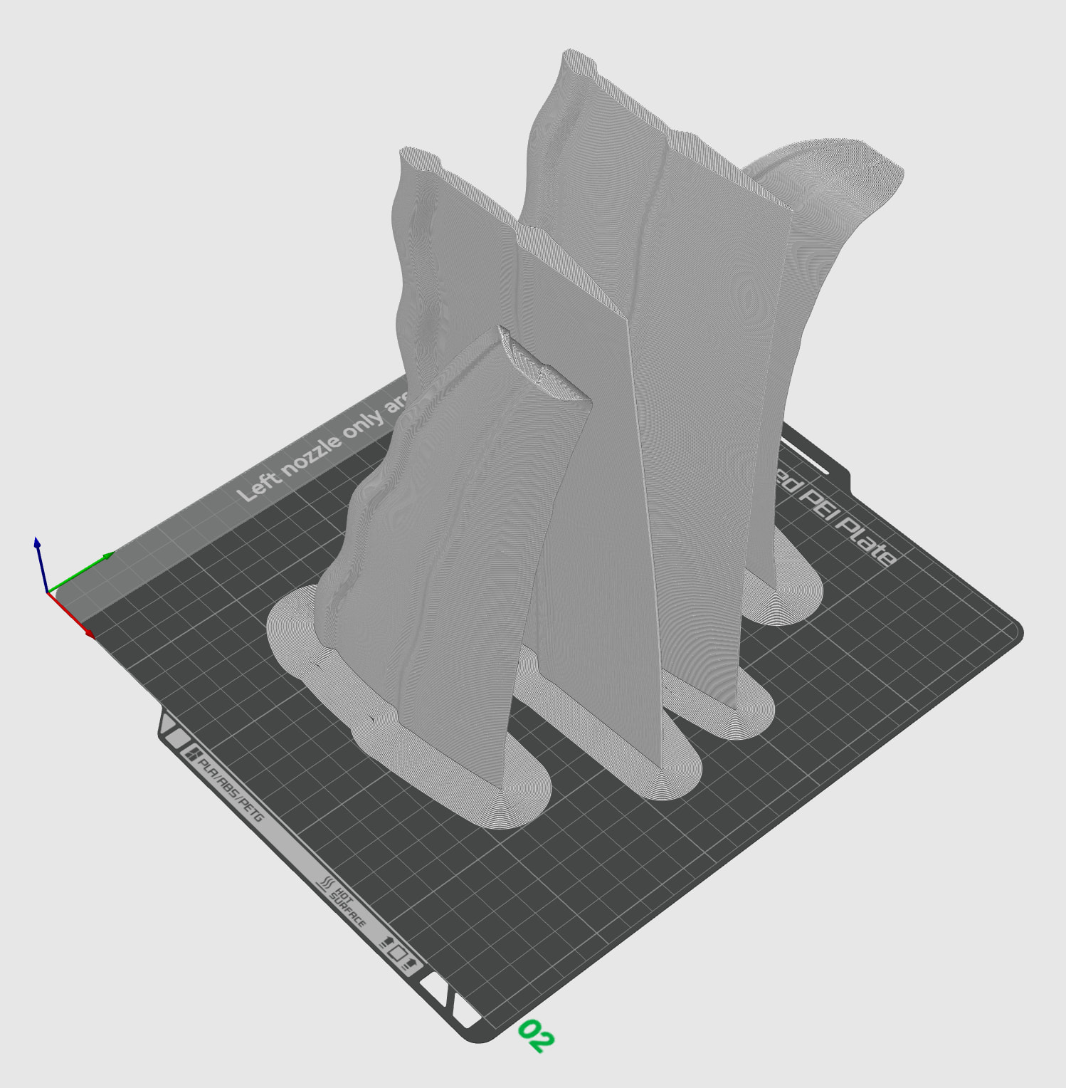
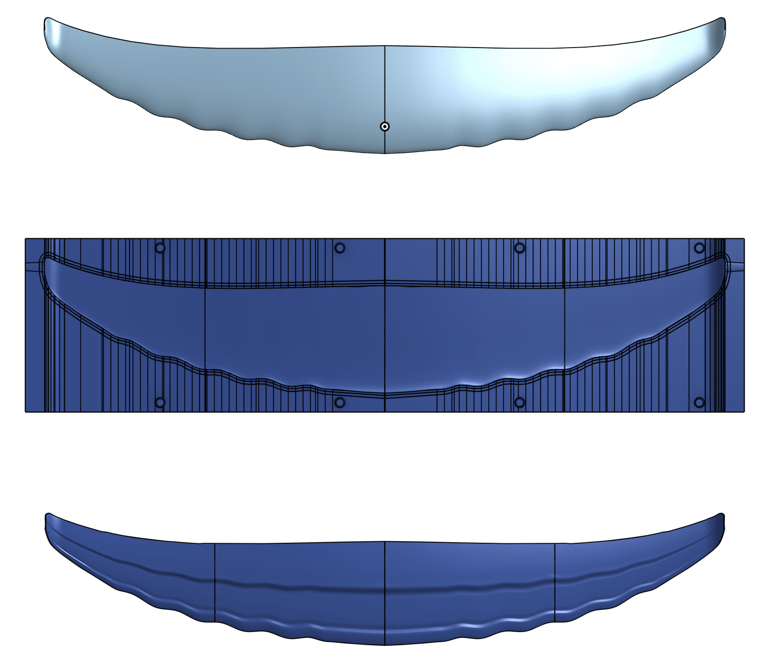
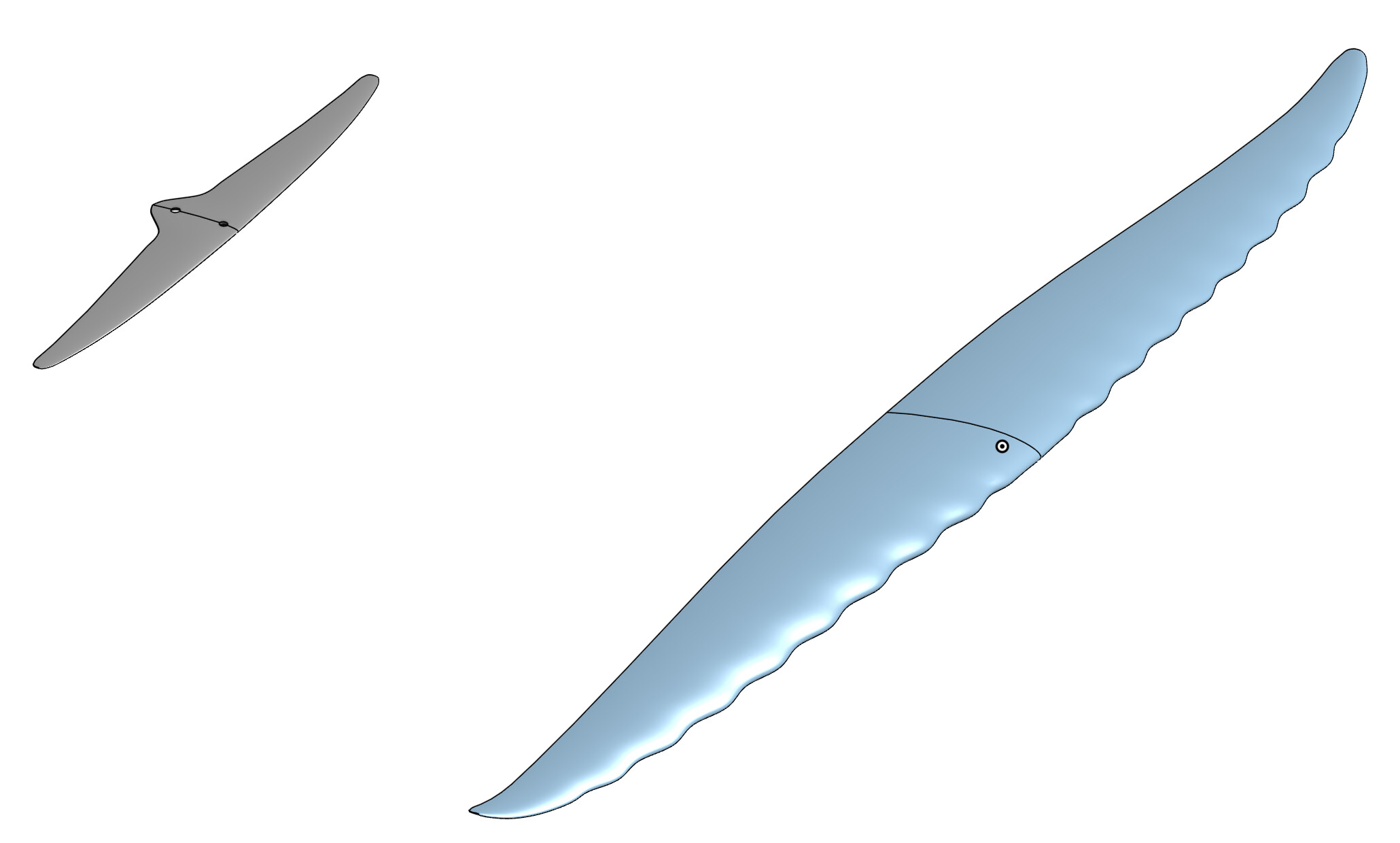
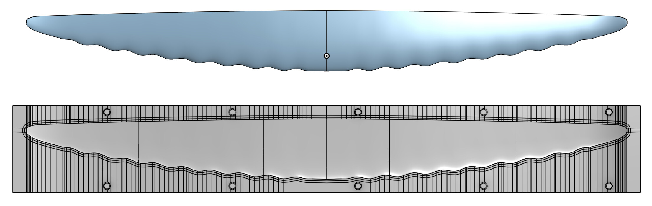
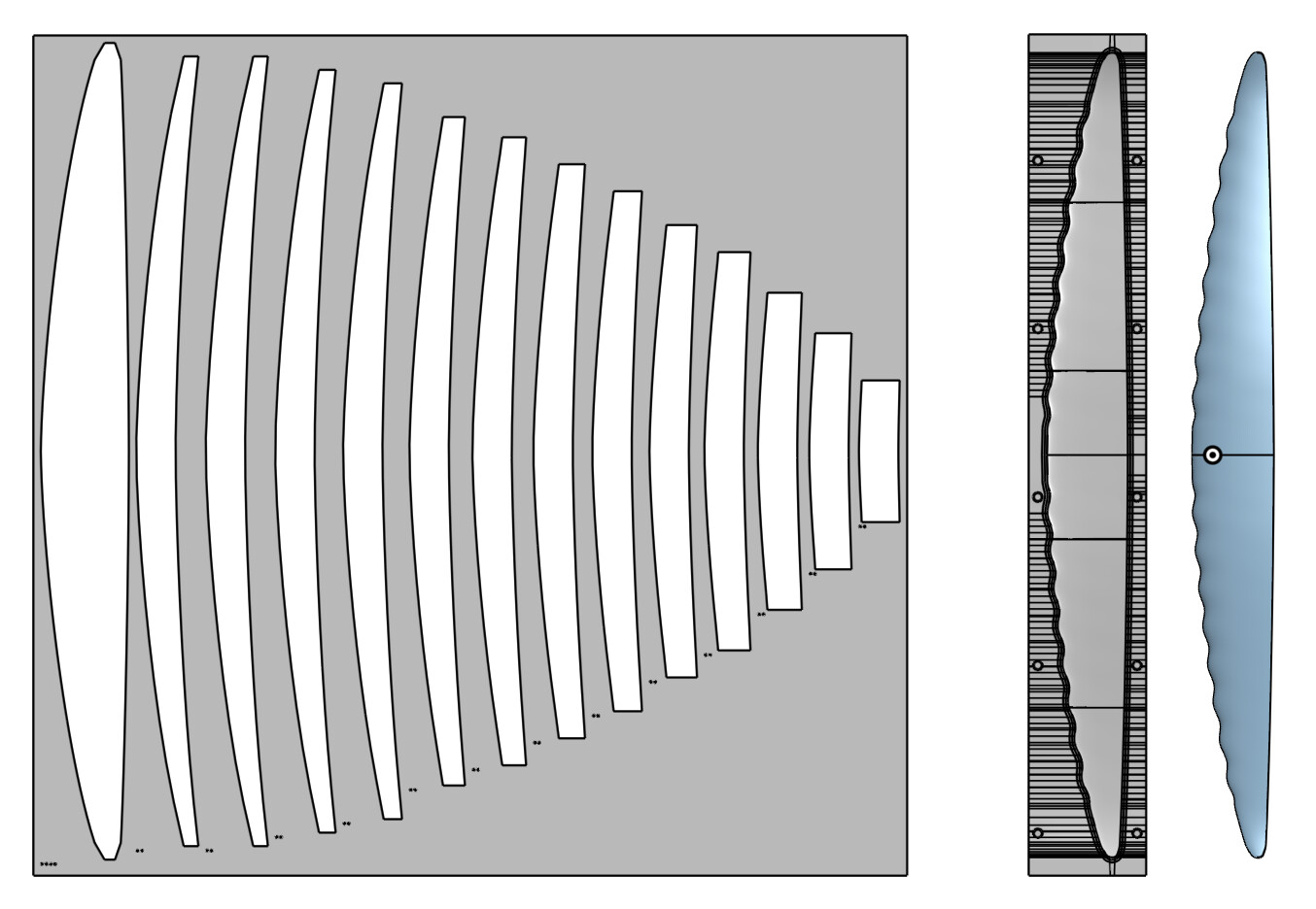
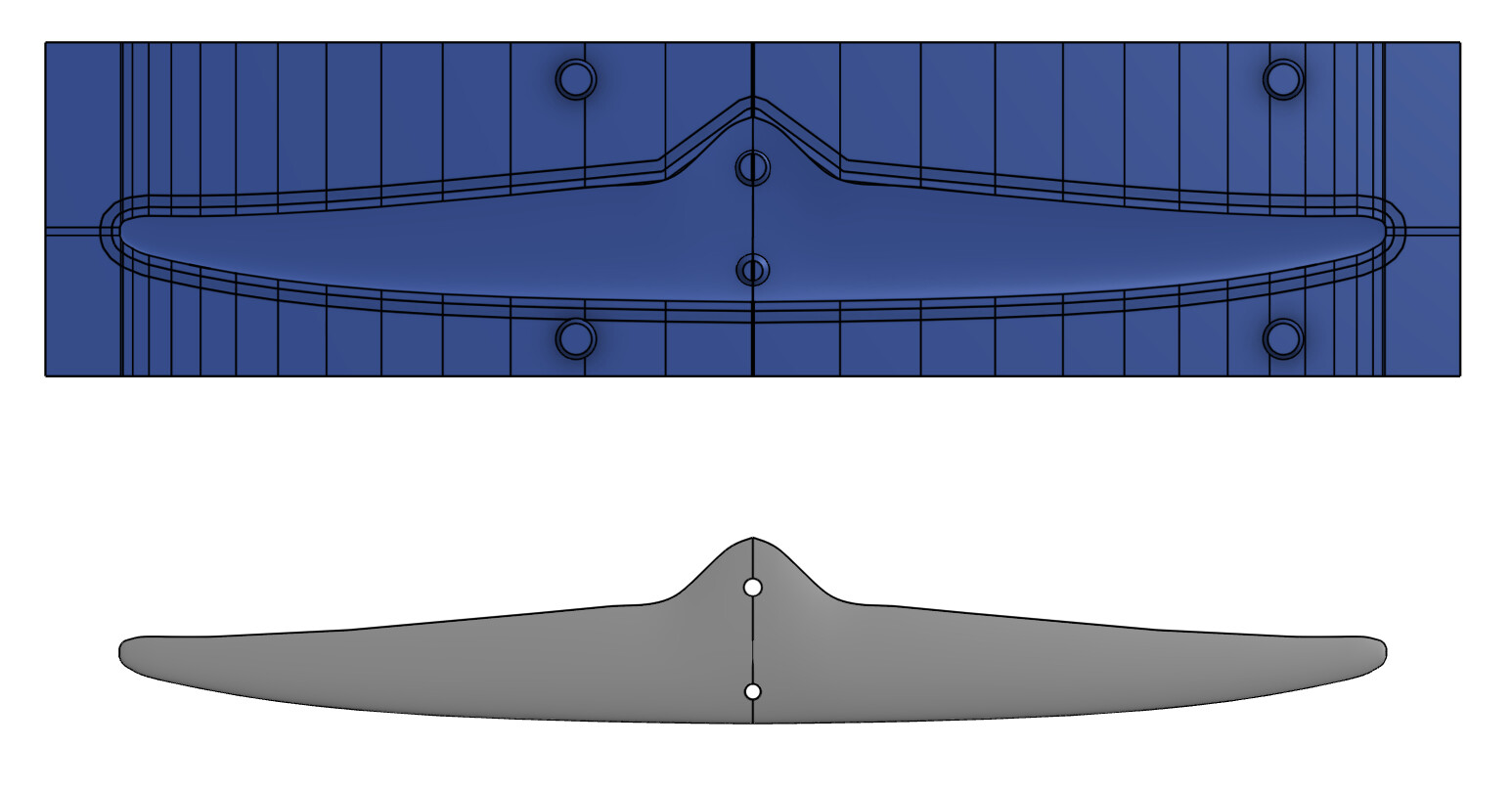
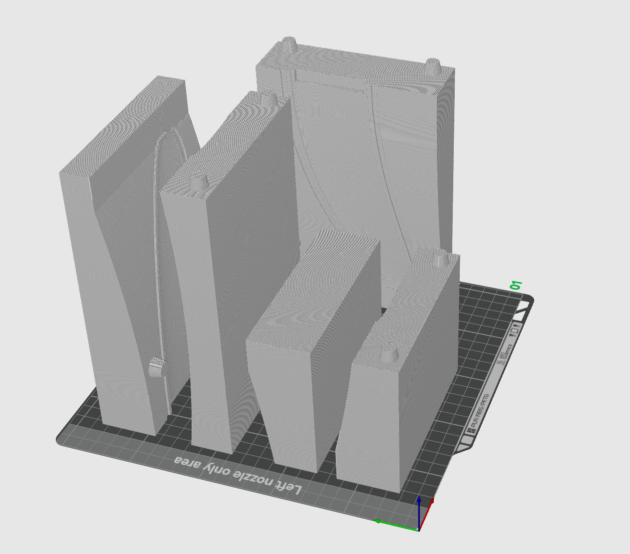
Pick the finished part and it makes the mold. Two shells parted along the camber line’s silhouette so both release, with flanges, locator keys, and a pinch-off groove so the excess resin squeezes out when you clamp it. It tiles the shells to your printer bed with staggered joints and keys between tiles and keeps the joints off the awkward bits. Plugs for the tube socket and the pod come off the part’s own cavities, so if you model your motor’s real shape into the pod the plug follows it. Bolt holes in the stab mount are molded as undersized tapered cones and drilled after cure. The mast comes out in three pieces, left, right and a tray for the plate. Its all parametric so you can choose as much or as little as you want, you can also tune parameters and use the logged data with the included skill for Ai to analyse." becomes "It’s all parametric, so you can choose as much or as little as you want, and you can tune parameters and feed the logged data to the included skill for an AI to analyse.
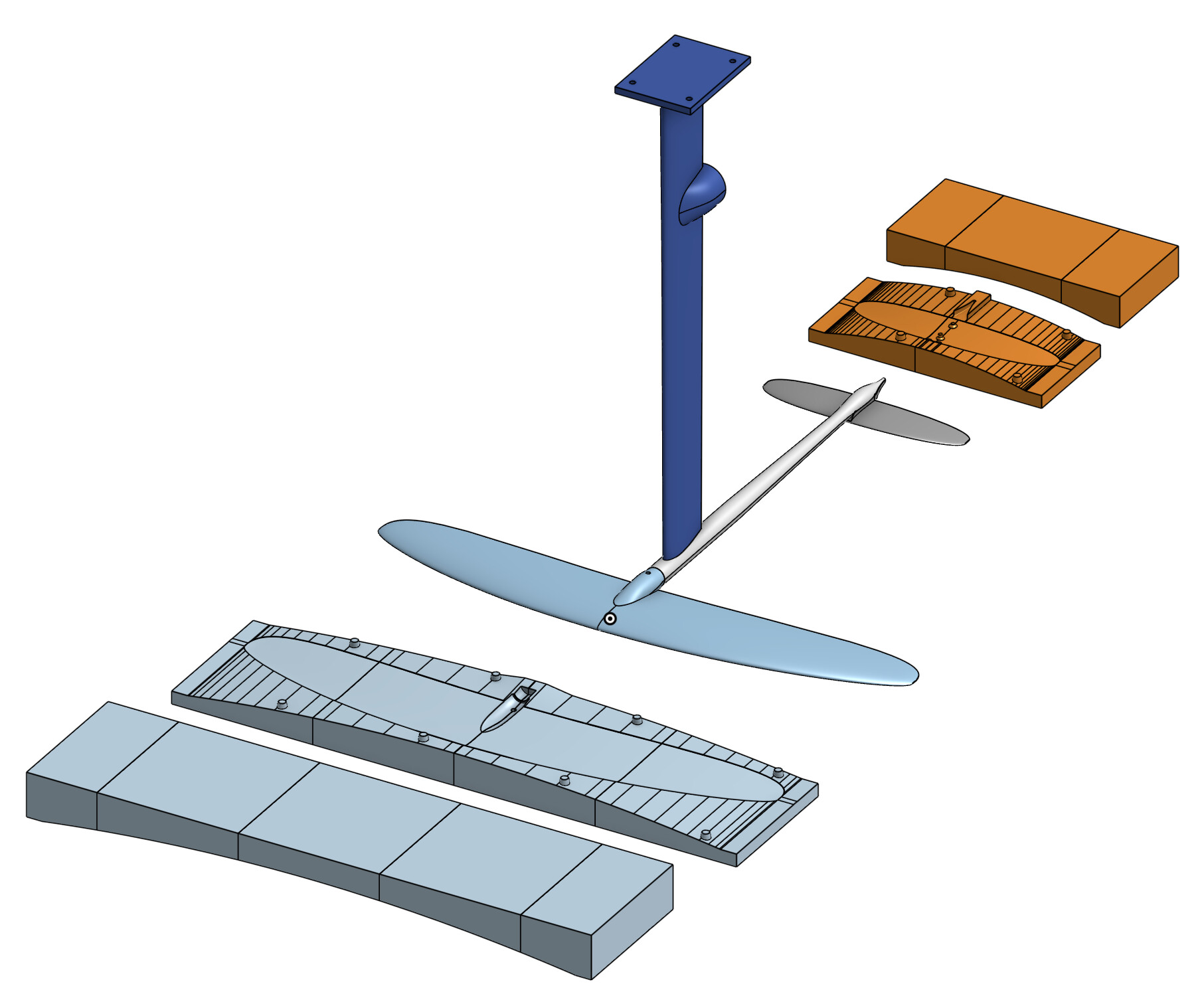
Then the layup, which it works out from the part itself. The volume is the laminate, the surface carries the woven skins, the UD caps are a percentage of the core over a percentage of the chord and taper ply by ply along the span, tow fills the rest. It prints the cut list per cap, the material and resin, and a stiffness check off that layup, deflection and cap stress against the loads the performance sweep produced. For the mast it also checks the plate junction, which turned out to be the weak point until I ran the caps out over a fillet with UD tabs interleaved into the plate. Turn on cut templates and every skin and UD outline lands on a flat plate with tally holes for the cut count, and the top face exports as one DXF.
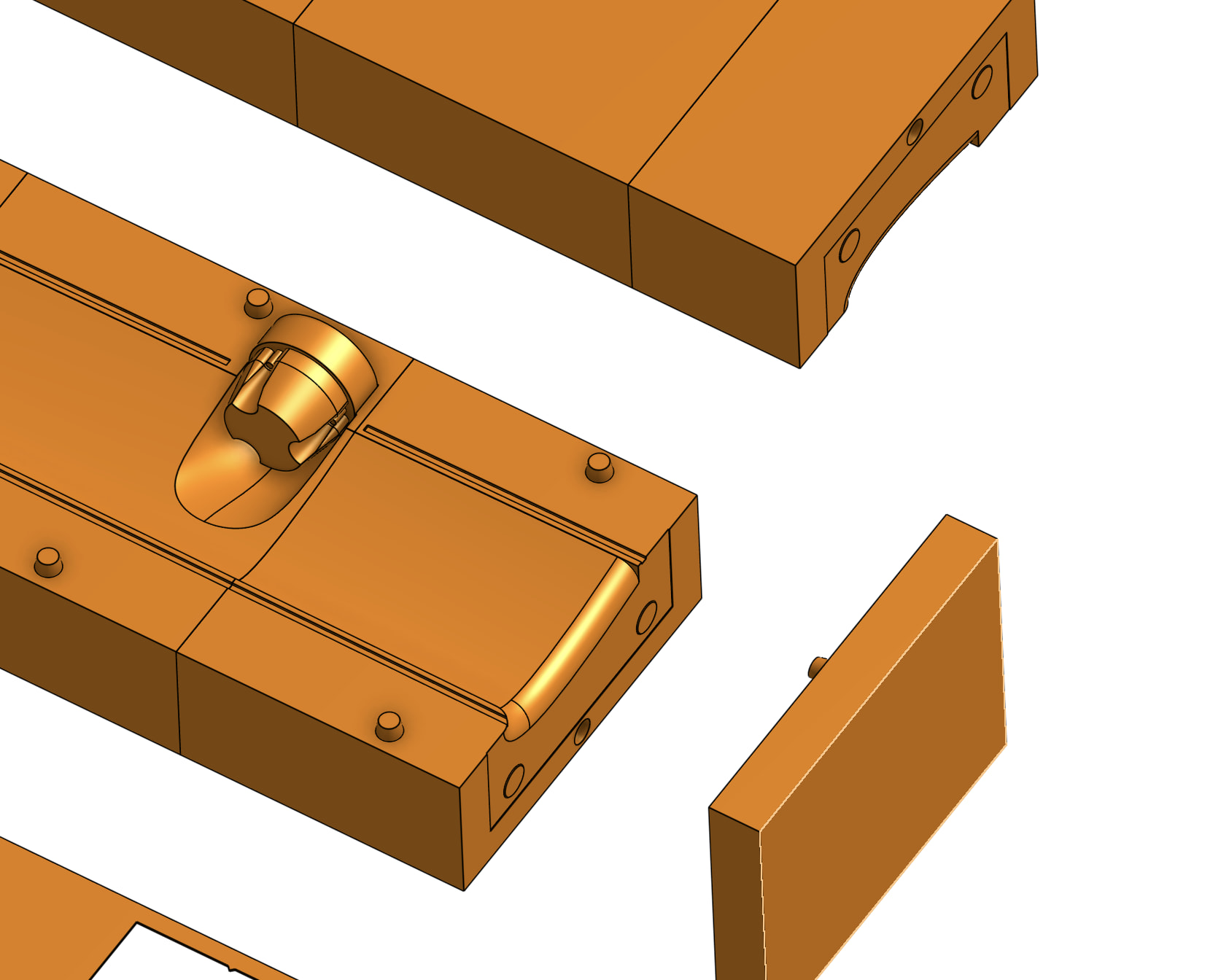
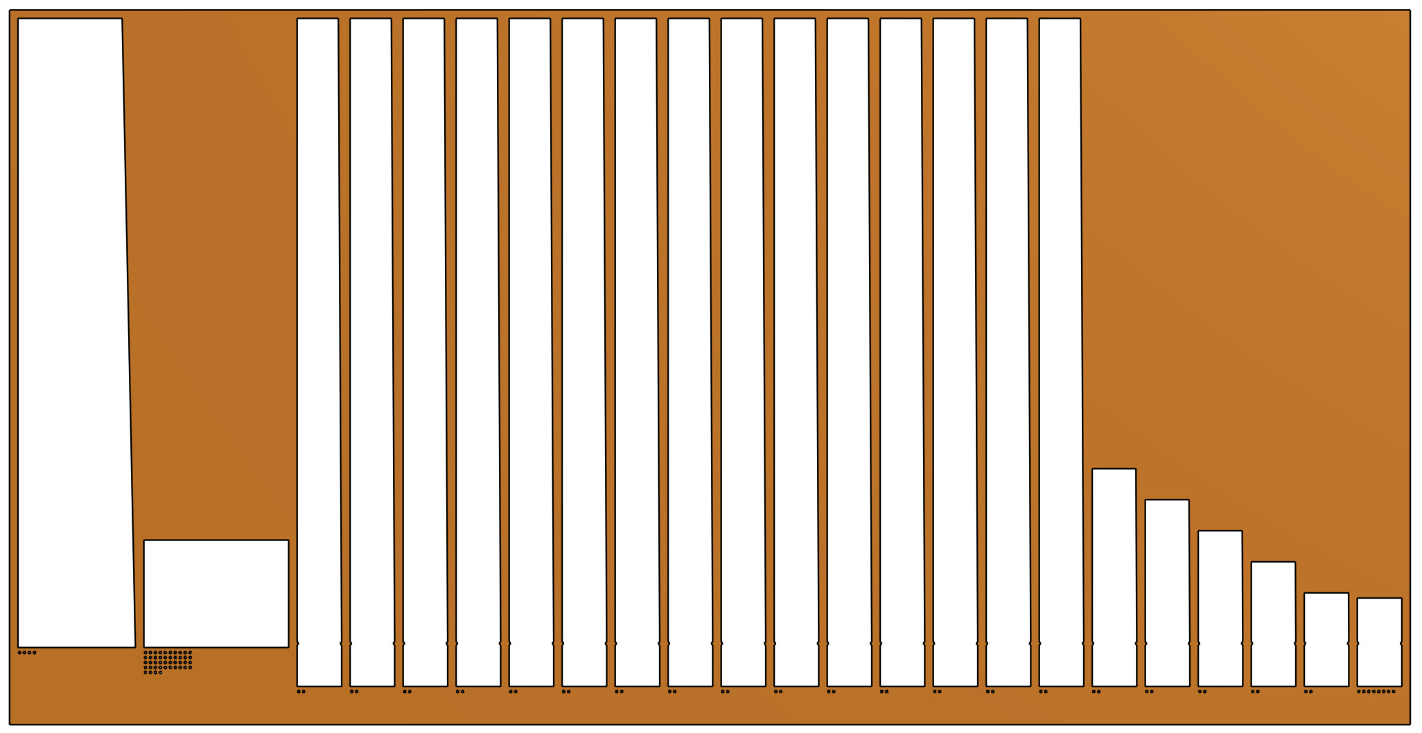
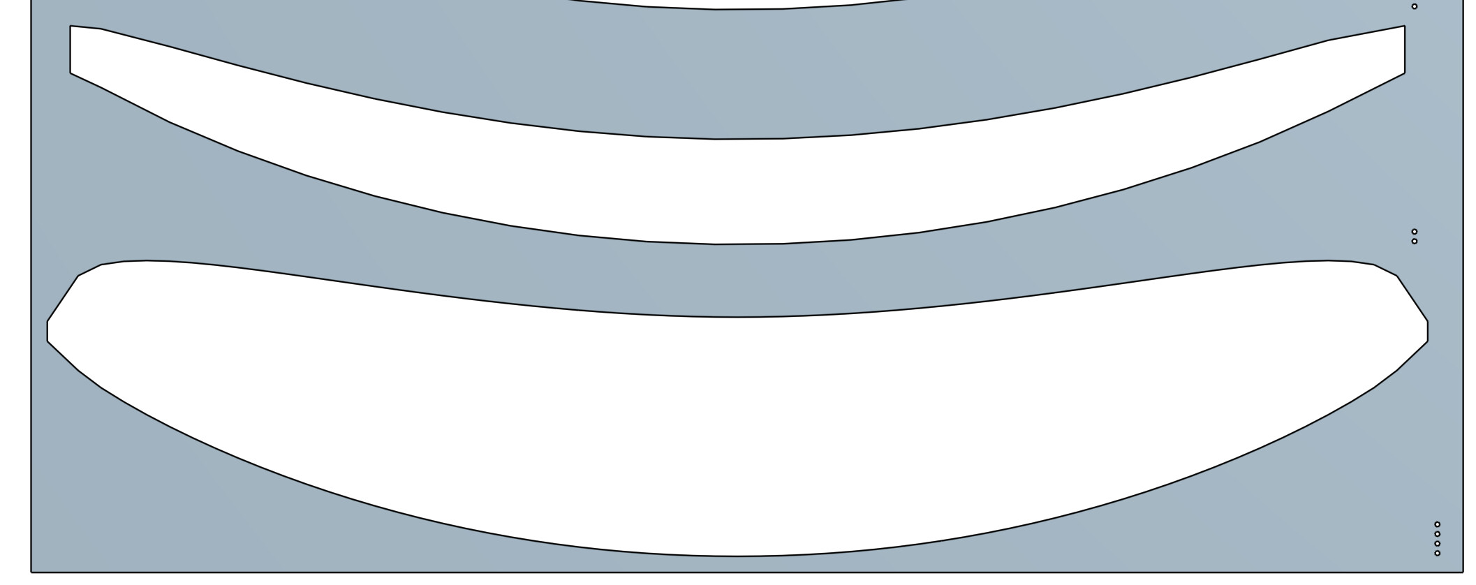
The process it assumes: PLA molds off a bed-size printer and faired for smoothness, wet layup of woven, UD and tow, clamped shut, holes drilled after cure. The plastic is the tool, the foil is carbon.
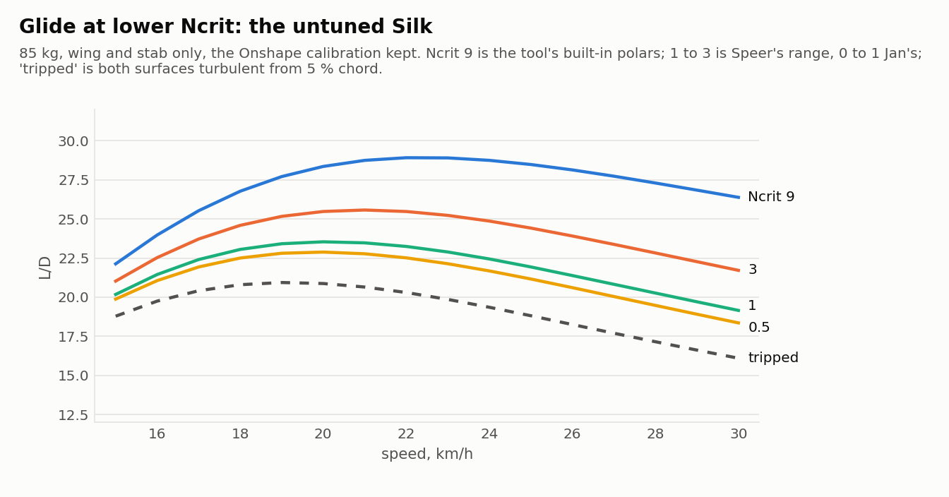
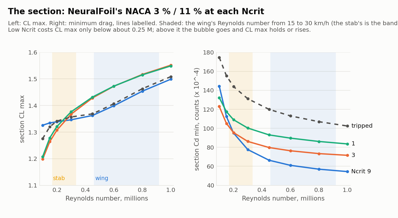
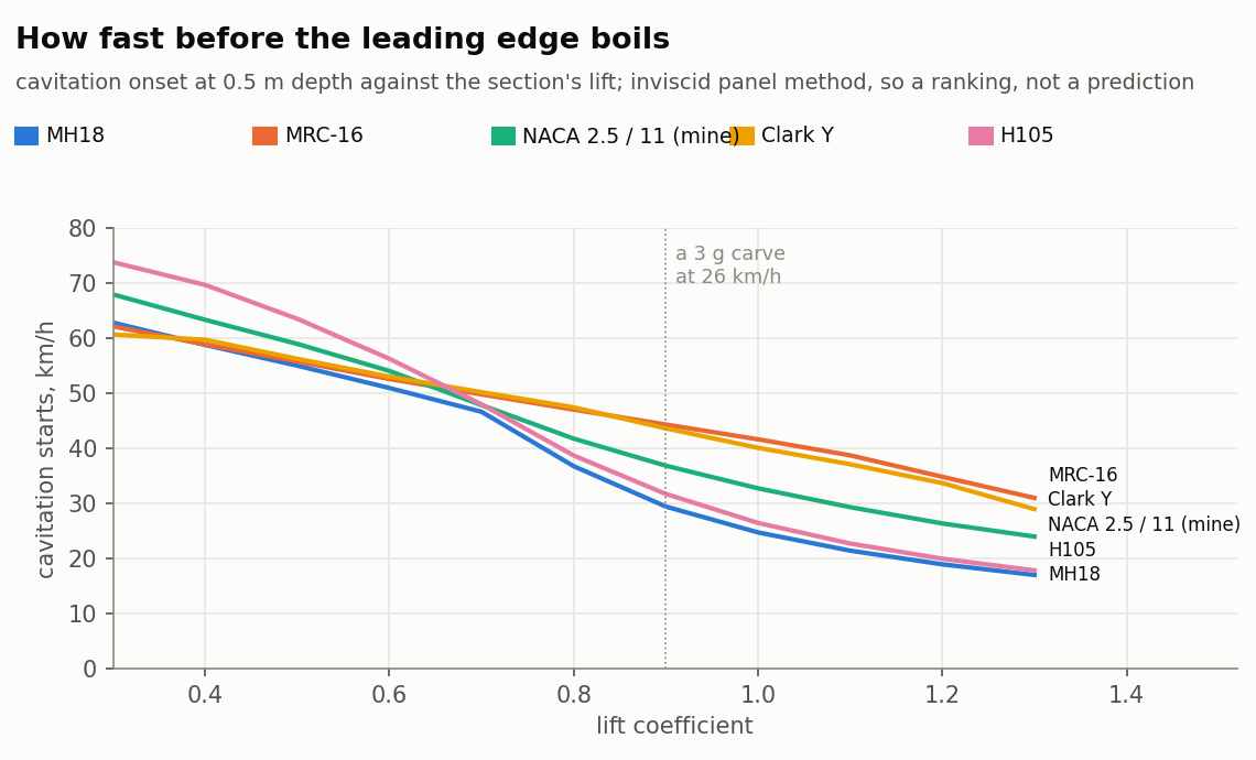
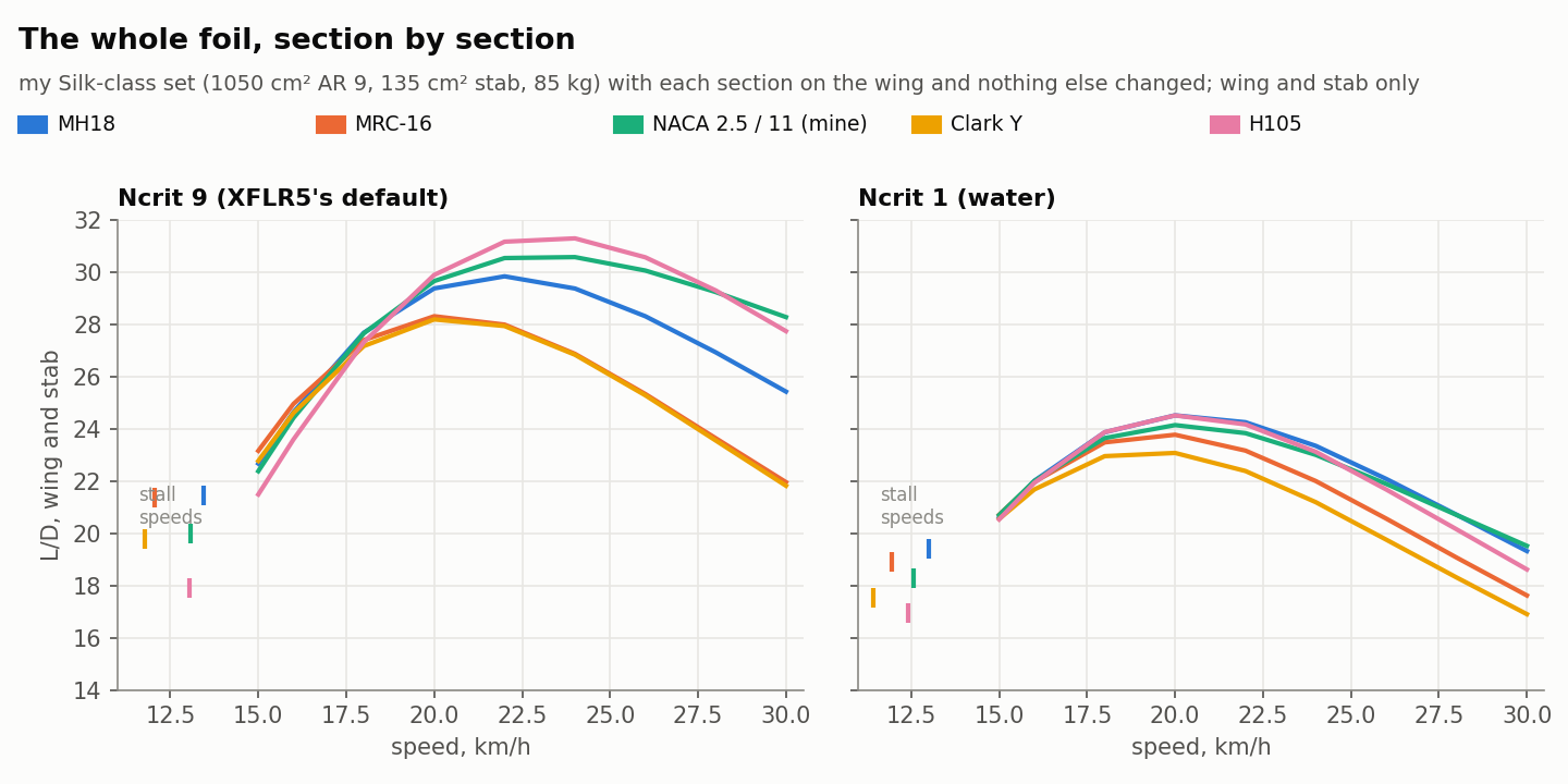
What it isn’t. It’s not CFD and it’s not dynamic. Every number is steady state: one speed, one weight, flat water, a rider who doesn’t move. Lifting line plus section polars, good for comparing variants, maybe 20–30 % on absolute profile drag. The prop is the B-series open-water estimate. The loads are static, a wing at n g and a mast with a constant side push, and real foils break on peaks and repetition, not averages. No fatigue, impact, buckling or ventilation, and cavitation is a number, not a prediction. What it’s for is that one field regenerates the whole foil, its analysis and its molds, so the trend from one version to the next is trustworthy and you can iterate in an evening. Then you build it and the water tells you the rest.
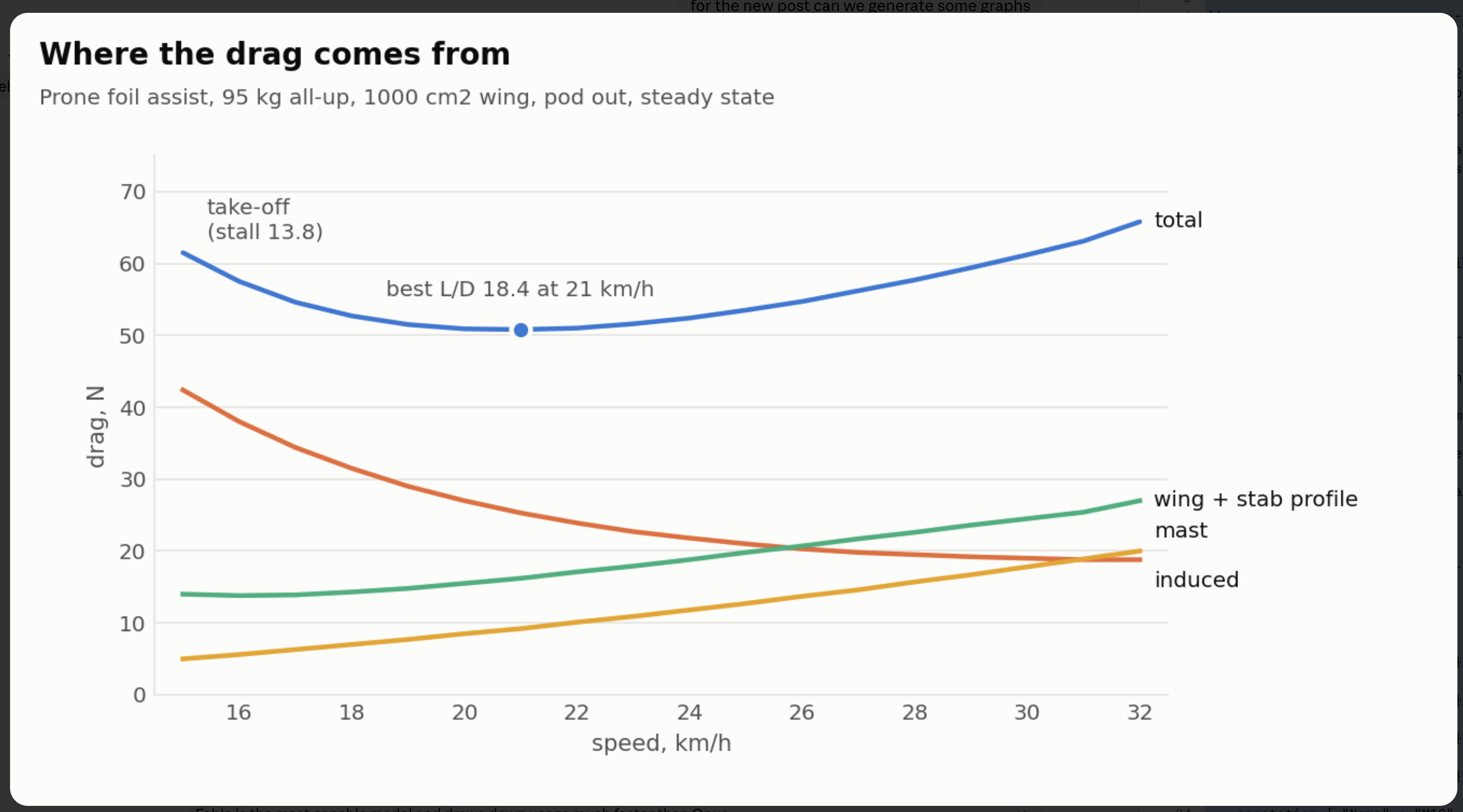
Here’s what it gave for a foil to test the theory.
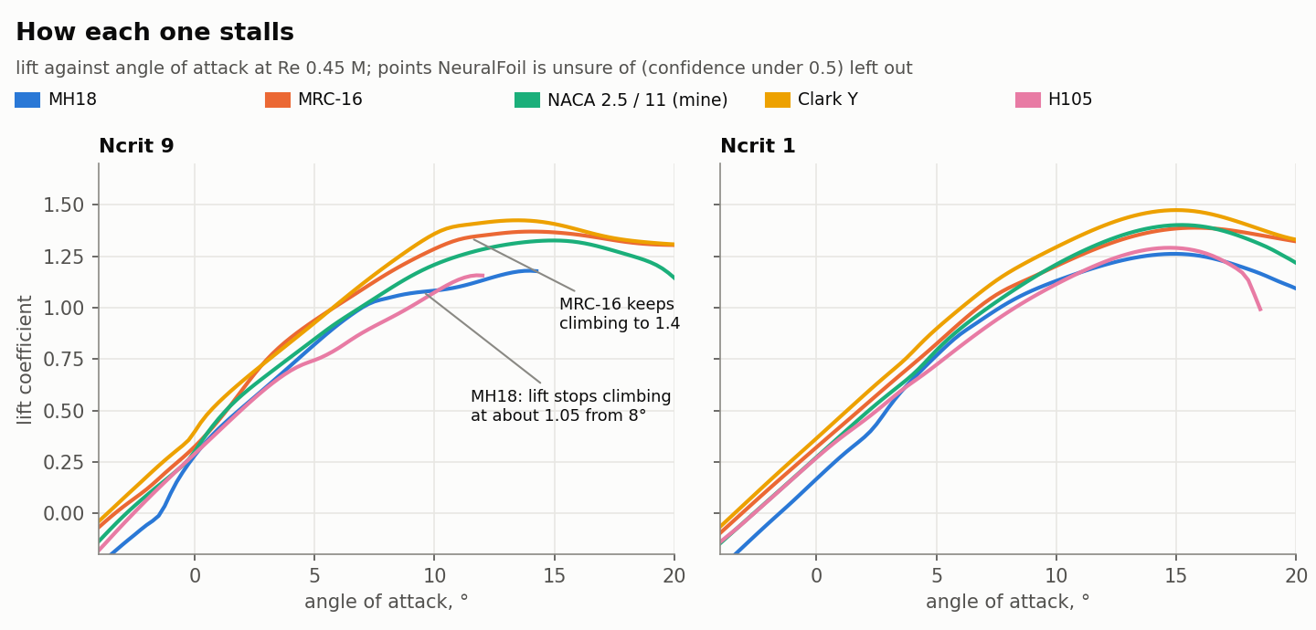
Prone wave foil assist, 95 kg all-up. 1000 cm² wing, AR 7.2, 850 mm span, NACA 4-digit 3 % camber, 12/10 % thick, 100 mm tip sweep, 30 mm tip drop, 1° washout, 1.5° incidence. Stab linked at 18 %, 180 cm², AR 5.7, symmetric, −1.5°, 660 mm back, two M5 bolts at 35 mm. Mast 750 mm, 100–110 chord, 16 mm going to 22 at the plate from 60 % height, 63 mm pod at 550 mm so it’s out of the water once foiling. 24 mm tube fuselage. Drive: 160 mm three-blade, P/D 0.8, 140 kV direct on 10S, 120 A, 20 Ah.
Pod out, steady state:
| km/h | board angle | CL wing | CL stab | drag N (induced / profile / mast) | L/D | W to hold it |
|---|---|---|---|---|---|---|
| 15 | 7.4° | 1.04 | +0.05 | 61 (42 / 14 / 5) | 15.2 | 256 |
| 18 | 4.1° | 0.74 | −0.09 | 53 (32 / 14 / 7) | 17.7 | 264 |
| 20 | 2.7° | 0.62 | −0.15 | 51 (27 / 16 / 9) | 18.3 | 283 |
| 25 | 0.4° | 0.42 | −0.25 | 54 (21 / 20 / 13) | 17.4 | 371 |
| 30 | −0.8° | 0.32 | −0.30 | 61 (19 / 25 / 18) | 15.2 | 510 |
Stall 13.8, so safe take-off at 15 is 86 % of the section’s CL max. Best L/D 18.3 at 20. Pod in adds about 7 N and drops L/D to 15.4.
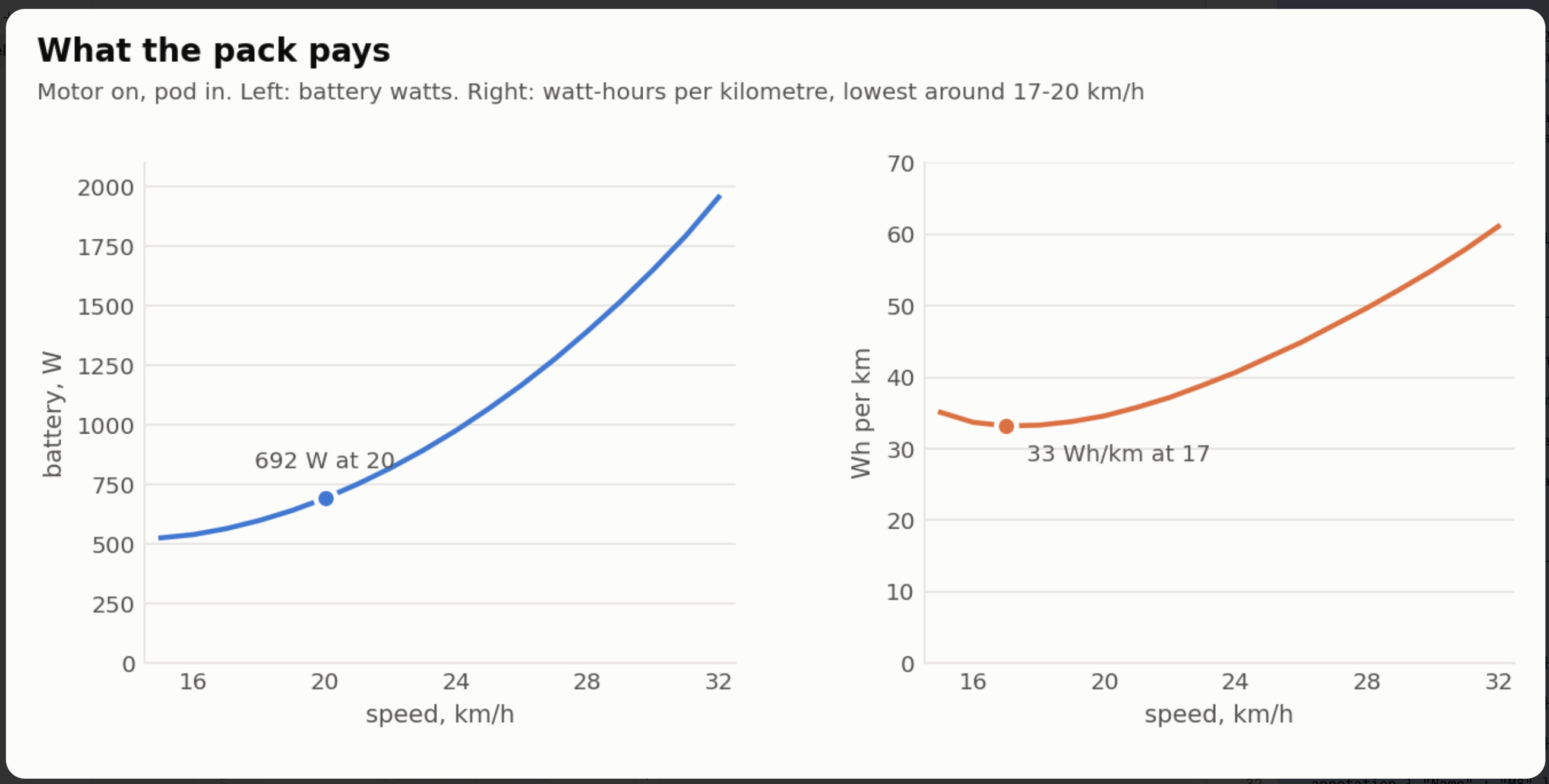
Motor on, pod in:
| km/h | thrust N | rpm | prop eff | motor A | throttle | battery W | Wh/km |
|---|---|---|---|---|---|---|---|
| 15 | 67 | 2150 | 69 % | 30 | 46 % | 526 | 35 |
| 20 | 61 | 2590 | 63 % | 33 | 54 % | 692 | 35 |
| 25 | 68 | 3130 | 58 % | 42 | 66 % | 1069 | 43 |
| 30 | 81 | 3690 | 54 % | 55 | 79 % | 1651 | 55 |
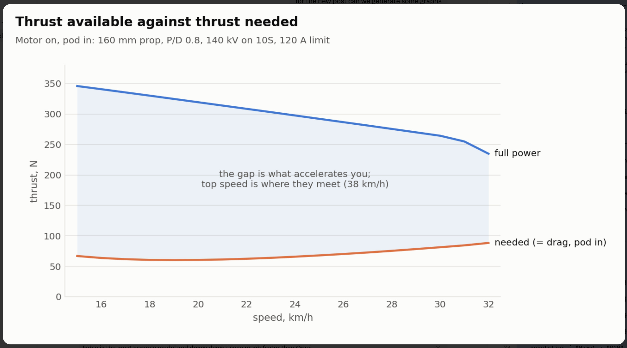
41 kgf static, top speed 38, 19 km or about an hour if you cruised on the motor the whole time, which on a wave board you won’t. V_S, you’ll notice the rpm: direct drive at 140 kV on 10S sits at 2600 at 20 km/h for the prop.
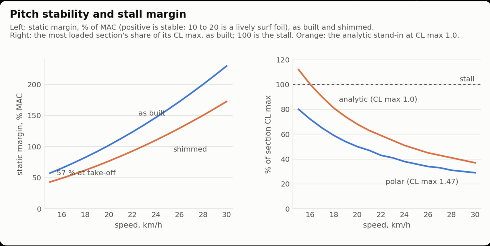
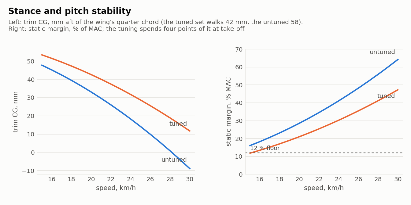
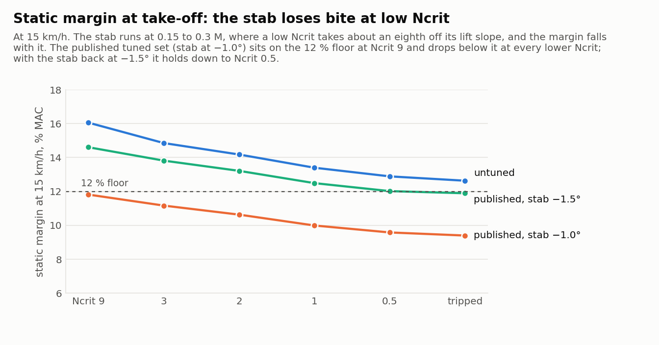
Pitch is the interesting one. Gliding, static margin is 30 % of MAC at take-off and 53 % at cruise. Under power the thrust line is 560 mm above the wing and 450 mm above where the drag acts, a 33 Nm nose-down couple at take-off, and the powered margin at 15 km/h comes out at 0.2 %. Neutral. You stand about 37 mm further back with the motor on. My first go had the pod 50 mm higher, a 150 cm² stab at 620 mm and 2° decalage and came out at −16 %, which I think is the number behind every “foil assist wants to nose in on the motor” post. Lowering the pod is the fix, and it’s the one lever the commercial kits can’t pull without putting the pod back in the water.
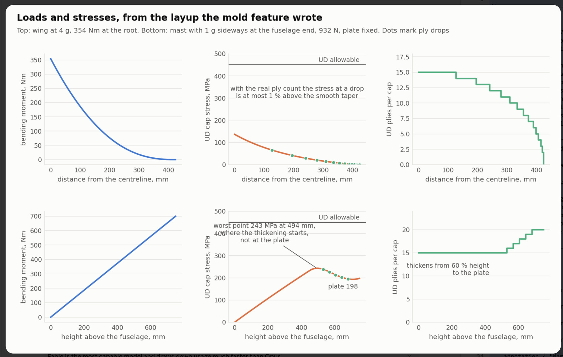
Structure, from the layup the mold feature wrote:
| part | case | layup | deflection | cap stress |
|---|---|---|---|---|
| wing | 4 g, 354 Nm at the root | 2 × 200 g woven each face, 15 UD plies per cap tapering to 4, tow core | 6.5 mm at the tip | 137 MPa |
| stab | 4 g | same skins, 5 UD per cap | 1.9 mm | 100 MPa |
| mast | 1 g sideways at the fuselage, 932 N | 20 UD per cap at the plate, 15 at the foot, 4 tabs per face into the plate | 53 mm at the fuselage end | 198 MPa at the plate |
Mast junction 38 kN cap force, 2.1 MPa shear against 15 allowed, 3.9 kN per track bolt, 96 MPa in the plate. Wet-laid UD is good for 450 or so, so there’s a factor of two at loads a wave session won’t see.
Materials at 50 % fibre: wing 1.6 kg (0.43 m² woven, 1 m² UD, 600 g tow, 830 g resin mixed), stab 0.13 kg, mast with plate 1.9 kg. About 3.7 kg of carbon and epoxy for the three molded parts. Wing mold 225 × 899 × 91 in nine tiles for a 250 mm bed, stab in two halves with the cones, mast in three.
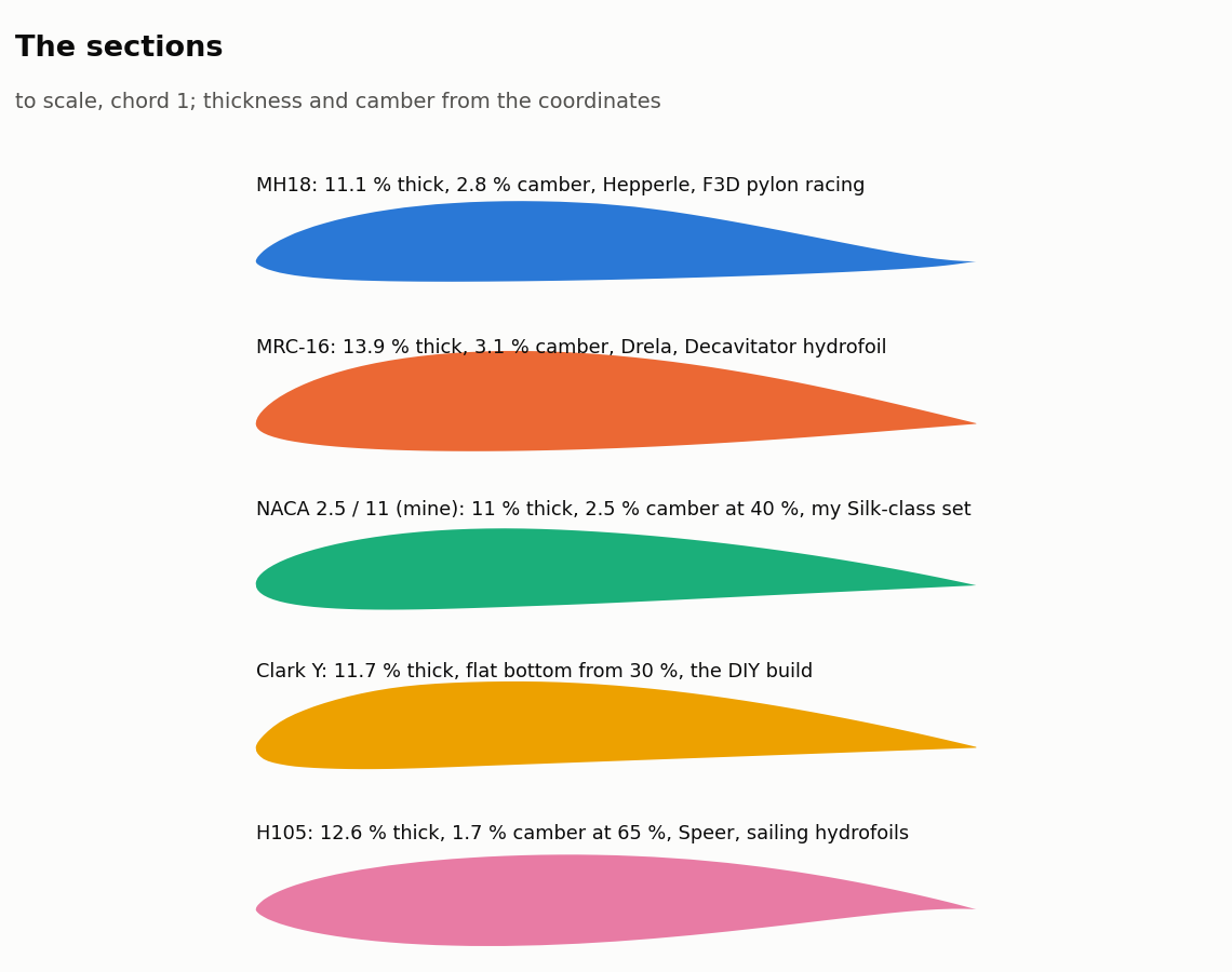
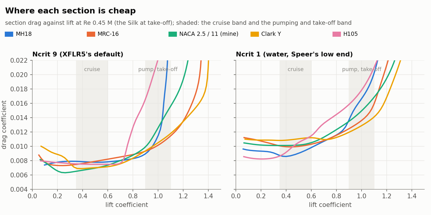
Photos of the molds and the template plate to follow. Sections are a dropdown with built-in polars, NACA 4-digit, E817, E818 and NACA 63-412 from their coordinate tables, or add your own: there’s a polar group that takes thirteen numbers off an XFoil run so stall and drag come from the real section rather than thin-aerofoil theory. Yes, it’ll be public on Onshape next to the blade generator once I’ve found what else is wrong. There’s a PDF guide half written.
The bit that brings this back to the prop. Everything the mold feature had to learn the hard way applies straight to blades and hubs. Part along the camber line of each section and both halves release. Print the locator keys into the flanges with a bit of draft. Put a pinch-off groove round the cavity so the clamp squeezes the flash out instead of the laminate. Mold holes as undersized tapered cones and drill them after cure, never try to mold a bore to size. Take any plug or core off the part’s own cavity, so the pivot bore, the gear pocket and the shaft bore in a folding hub come out as cores of the mold rather than things you model twice. Tile to the printer bed with staggered joints so a 200 mm blade doesn’t need a big printer. A blade is just sections along a radius instead of a span, and a hub is a lump with holes in it, which is easier than a wing with a socket. So the next thing the blade generator could get is a mold feature: pick a blade, get two shells and a plug; pick the hub, get the same.
What I’d like to know from people here is which bit is actually useful, the mold and layup side, the performance side or the range stuff, and if anyone has measured drag or deflection on a known foil I’d like to check the model against it.
End game it kept me entertained on the flight.