I have made a small software mod for a friend. It makes the steering less sensitive at high throttle. With that there is less risk of tipping the boogie while steering. I can upload the code tomorrow if you’re interested?
Yes I am. It won’t change the low speed steering capability?
No, basically the more throttle you give the lighter the steering gets. But low throttle steering is the same
Sounds pretty awesome!
Hey, awesome build. Could I ask what models you are using for your propellers?
If you were going to start from scratch with everything you know, what ESCs would you go with for your 6384s?
Thank you!
Yes, Same question. Looking for STLs for Left & Right turn 3 blade props. Ideally like (hyper drive).
For left and right props just mirror in your slicer
https://lbre.de/hp/fs/slowSteer.rar
Try it out, the function needs to be enabled in the SHARED_CONFIG
Not tested so far, so I would be happy for some feedback
Lines 292 and following regulate the amount and when the limit starts, if you wanna play around with that
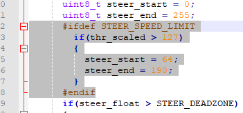
In the if() a higher number will make the limiter only be active at higher throttle (currently set to half throttle)
The _start and _end need to be symmetrical to 127, between 0 and 255
So setting to them to 0 and 255 would be “normal” steering and both to 126 and 128 would be absolute minimum steering
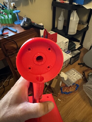
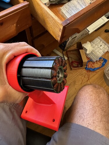
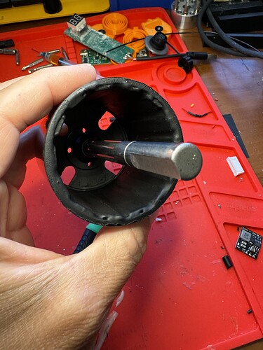
Updated the motor pods so it will hold the front bearings of the motor in without epoxy. Also, no need to cut the motor shaft if you don’t want to. It’s updated on my printable’s.
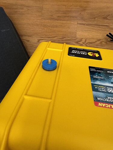
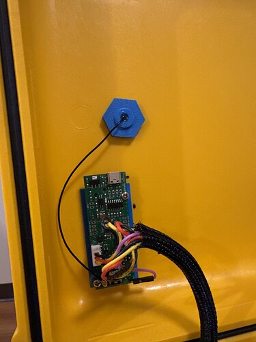
Ya I made a thru box connector that has the male connector on it. It’s filled with epoxy and made a silicone mold for the gasket. Completely got the idea from the @hangloose connectors. Then the external antenna just screws into the connector.
Im using a fixed 2 blade by @V_S. He has quite a few different ones you can try. I’ll try and find the link to his page with all the props.
The flycolor x-cross 120 or 160 amp work great and they’re aren’t super expensive. You have to run a BEC for each of them, which is not difficult. I think I will continue to use them and would have made my first boogie with them.
Great work. I like that idea a lot for my next prone board with the foil drive inside. Currently I am just taping the antennae extension to the outside of the box directly over the location of the internal antenna and that is working a treat but it is a hassle to have to keep taping and re-taping. Your is next level. Mind sharing with me the STL’s for the internal and external covers you made?
Just a few questions (my BREmote is in the mail).
- In the Flycolor manual it looks like the BEC connects to the receiver, which then connects to the ESC over the signal and GND wires. What is actually happening here? Is the ESC getting 5V from the receiver? Or is this just for the BREmote receiver?
- Why do we need two BECs, one for each Flycolor?
- What sort of current draw do we need? I can’t find it anywhere.
- I found this this on Amazon, which seems reasonable, but could find anything that would work up to my 12s pack voltage. Is it an ok plan to tap off of half of my pack to supply the BEC?
- Do we need one of these things to program the Flycolors?
Thank you so much for the help!
- In the Flycolor manual it looks like the BEC connects to the receiver, which then connects to the ESC over the signal and GND wires. What is actually happening here? Is the ESC getting 5V from the receiver? Or is this just for the BREmote receiver?
It is just the BREmote RX that is getting power from the BEC. I will try and draw a diagram for how to hook it up.
- Why do we need two BECs, one for each Flycolor?
You are running two different PWM signals and need power to each one on the RX board. It just works better to run 2 BEC’s. I have never tried, but I think others have tried running one without great success.
- What sort of current draw do we need? I can’t find it anywhere
I am not sure. @ludwig_bre recommends 2 BEC’s as well and he is far smarter than most of us, he is an engineer.
I use an Arduino to program the flycolor. It’s really easy. Others have Bluetooth solutions and I think if you search BL_Heli on the forum you can find more info.
I don’t think splitting the battery to meet your voltage requirement for the BEC is a great idea, but it would probably work, just make sure you run grounds to the speed controller main negative pad and the small ground pad. I use these BEC’s and they work good.
Hopefully we can get some other opinions on this stuff as well. I like hearing different opinions.
I decided not to pot the motors anymore, the motor that has held up the nicest is my fake foil drive that I only use corrosion x on. I did epoxy the can so the magnets don’t work loose. I am however painting them with rustoleum paint and will still coat in corrosion x every use. I need to order one more motor and will try and take the time to video how I prep the motor from start to finish.
The problem in short:
When the ESCs draw current from the battery, the voltage on the supply wires drops, also the negative supply will not be exactly at 0V anymore.
As both ESCs draw different current sometimes, the both GND potentials will deviate from one another
However, the PWM control signal is always relative to the GND of each ESC. So if you have one BEC, connected to the GND of the 1st ESC, it will work nice with that one but if the 2nd deviates the PWM is invalid and the motor will stop
So having one BEC each ensures a reliable voltage potential each.
The V2 BREmote I am currently developing will have this solved, only needing one or maybe even no BEC as is will have one built in, but that I still need to develop ![]()
I can’t wait to see the V2!!
Great description @ludwig_bre, makes a ton of sense.
Thanks for the link @Jesserosco!
I also can’t wait for V2 ![]() Also excited for my V1 long range to arrive to start using it.
Also excited for my V1 long range to arrive to start using it.
I need to order one more motor and will try and take the time to video how I prep the motor from start to finish.
Would love a video. I ordered two of the flipsky battle hardened 6384s. I am curious if I still need to replace the bearings with ceramic.
