I’m interested in learning more about this capability. I know a little bit but can’t find much detail by searching forum.
I know a few have gone about this with some kind of tether between rider and board as a “trigger” for when you fall off and that VESC supports the function.
I think some commercial builders have done something like this (Takuma) but I recall that Flite has some kind of auto shut off if the rhe board heeled abruptly.
If anyone can supply detail about how they did this, associated risks, reliability, effectiveness etc and/or detail about what commercial builders did I would appreciate it.
But I have considered implementing something like this, but did not get beyond the initial stages.
It should be reasonably easy to do with gyro data of the board. When not in a failure situation, the board has only very limited range in pitch and roll.
Once you fall of the board, the board pretty much always does something aggressive in pitch, which should trigger the motor to turn off.
As far as I know (have never seen a Takuma in person) they used/use a magnet to attach to a point on the board on the hatch. When the magnet comes off it somehow triggers a stop.
This is what is posted on the Fliteboard site about their method.
Some manufacturers rely on the remote losing contact when it’s underwater, after you fell
Shut-off with gyro in Rx or Tx is a option too, requiring more programming though
Magnet+Foot strap gets in the way sometimes, I personally don’t like it
No matter what you do, always cut the signal to the ESC or use the VESC cutoff input, but DO NOT cut power to the esc while it is spinning a motor. That can lead to destruction of the ESC.
Yes I picked up on that from the topic @windego linked!
After reading that topic (not sure why I didn’t find that one myself) and some Googling . I have the impression that the Hall effect switch (thankyou @Larsb ) is more reliable than reed but the issue of where to place the “trigger” magnet so it’s not in the way (and of course the lanyard being a trip hazard) and the potential for getting stranded if I lose the magnet has dampened my enthusiasm for the idea.
I’m also not clear if the Fliteboard I use would require a mod that would compromise the waterproofness of the hull. I know that the magnet doesn’t have to touch the Hall effect component of the circuit to work in air but would it work through the existing hull material as I’m extremely reluctant to drill any holes in the board.
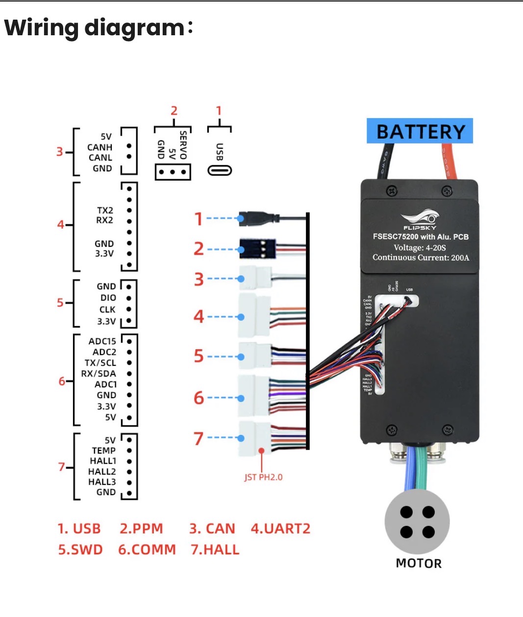
Logically I would use the COMM port for the Hall switch for ACD2, GRD and 3.3V but in my case it’s already occupied but GRD is the only one of those that the receiver uses (TX,RX,5V,GRD).
Is it good/OK practice to make a wire harness connector that would give me the three pins I need from the COMM port. The GRD would be “shared”
Yes I’m thinking of a leash based system rather than an imu - acute angle type for a few reasons.
The leash type would work in scenarios where the motion type wouldn’t. I have come off my board where it travels quite level until it stops but your correct either type might not trigger in all situations to prevent injuries.
My reasons are
Prevention of runaway board scenario - leash would “always😉” work imu might not
Secondary shutoff to back up normal trigger release/remote disconnect stop - either would work
Visible method - easy to demonstrate to public and/or law enforcement - leash method is external vs imu internal. Board doesn’t have to move to prove the system is functional, imu would require a “crash”
If you want to be real safe I probably would have the leash kill the power to the Rx of your remote completely.
If you use a hall sensor, get one with an output that can drive a small relay - use that relay to switch the supply line to your Rx
Otherwise connect the hall sensor power input to 5V or 3.3V on any connector, gnd to gnd on any connector, output of hall to ADC 1 or 2
And take a unipolar hall switch, not a linear hall sensor
Hall switch with strong magnets will penetrate CF+Styrofoam no problem for a few cm
I’m likely wrong as I have a rudimentary electronics understanding but it’s my current belief that the ACD2 connection to the VESC coupled with the KS function activates the VESC to cut power to the motor. The other connections would seem to work in a similar if not identical manner.
Your idea of implementing a relay / RX is interesting but I don’t understand why that approach would be “safer”. Could you expand on that please.
I’m also concerned about adding another component (relay) that could potentially fail or malfunction. I subscribe to the KISS method in most things
Because in that case you don’t rely on the VESC to cut power based on a software function that reads the killswitch input, but rather you take away the throttle signal completely.
Thanks for expanding I now understand the logic behind the RX approach but isn’t the RX also related/dependent on a VESC software function to work to some degree?
I’m a bit out out my depth on this stuff so thanks for confirming my undertanding of the ACD2 part of my post.
It is indeed.
ADC2 is less effort and basically same safety level. Make a wiring harness from any GND and 5V source to a suitable sensor and connect the output to ADC2, done. If you need help selecting a sensor I can assist
Cheap option is this: https://de.aliexpress.com/item/32824654109.html
Apart from having to drill a hole in the board, where the manget would keep the board intact, the open connection without water protection will probably be a problem…
when not closed the contacts will corrode very fast due to potential difference
this may couple a lot of interference into the VESC 5V and ADC, if the motor wires (even isolated) and those contacts will be both in the same body of water… a buddy once tried this and it never worked, until he completely decoupled/isolated the signal wires from the water
With saltwater the threshold where the opposite pogo pins close the contact but the salt water does not will require some tuning…