I don’t understand why they use 8AWG as phase wires. It’s redundant and very inconvenient to solder.
Did you use 2x0.2 as a minus?
We tested up to 165A on the 84100, but I agree 8awg IS overkill, 10 awg would be ok.
Using 60° H strip so total 4 x 0.15 x 7mm
2 Likes
Things go out of hand slightly. I think we are all confronted to this kind of issues ![]()
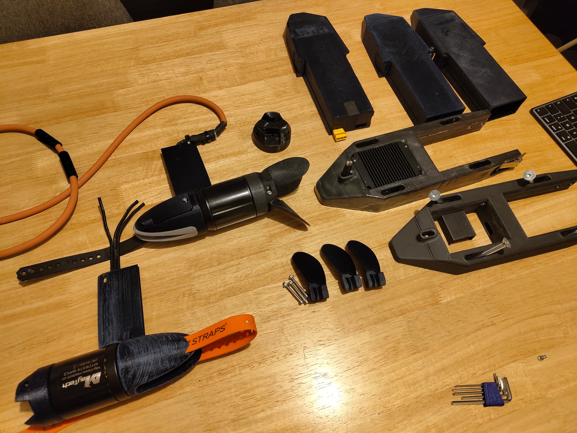
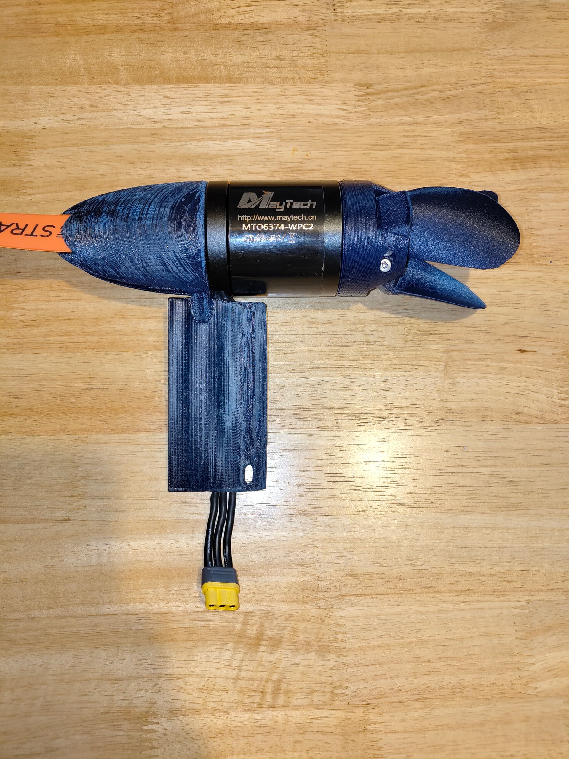
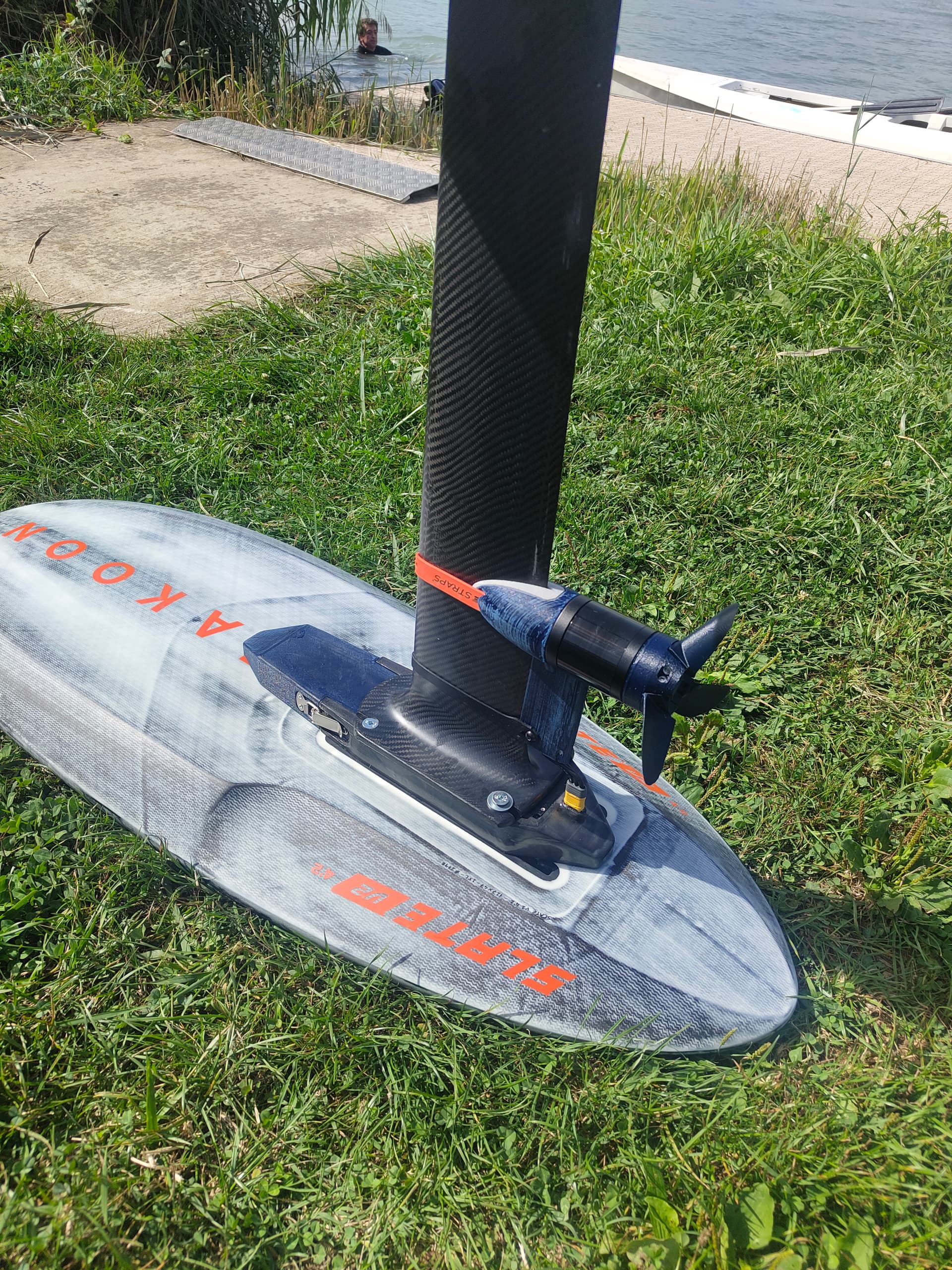
Printed the parts for the maytech POD, with three blade hub.
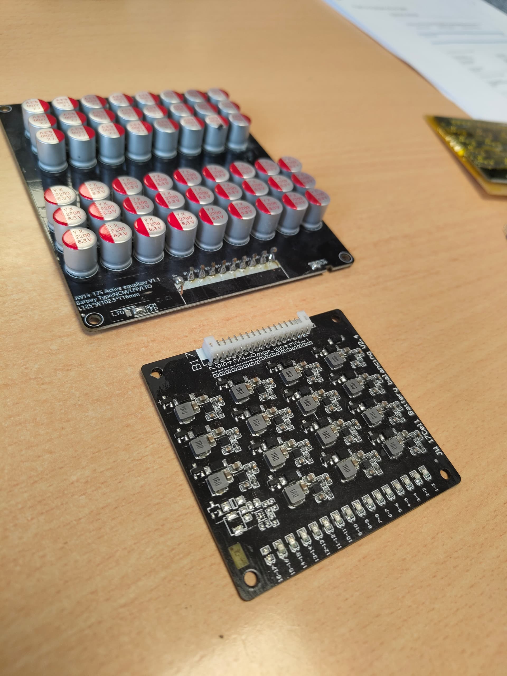
Found some active balancers that we tested before, the inductive (black) ones are not great, as they have 0.1v min activation voltage between both cells, so they create some sort of staircase voltage levels in a unbalanced pack.
The capacitive ones work very well in my experiance and super fast to balance out of whack packs, tested up to 10P
I will first test the inductive one as I hev the right connector for it.
4 Likes
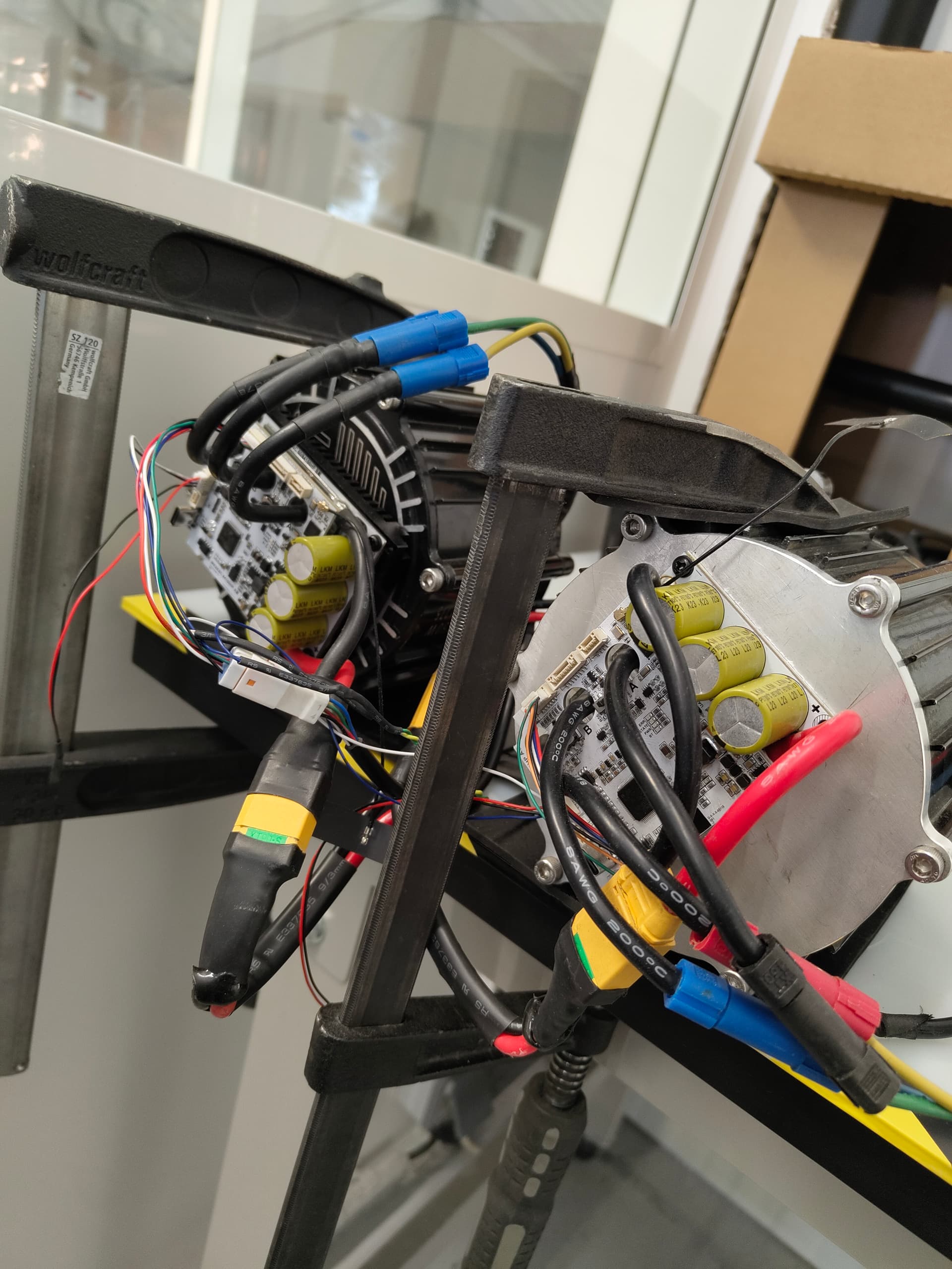
Have you run the Makerbase 84100 with the assist yet?
A Friend of mine has, for e-foil use, without external cooling, he was very happy with it.
We used them a lot for test bench tests, they are going into a motor we are designing, that has already 10’s of hours on the test bench. Can not share more, work stuff ![]()
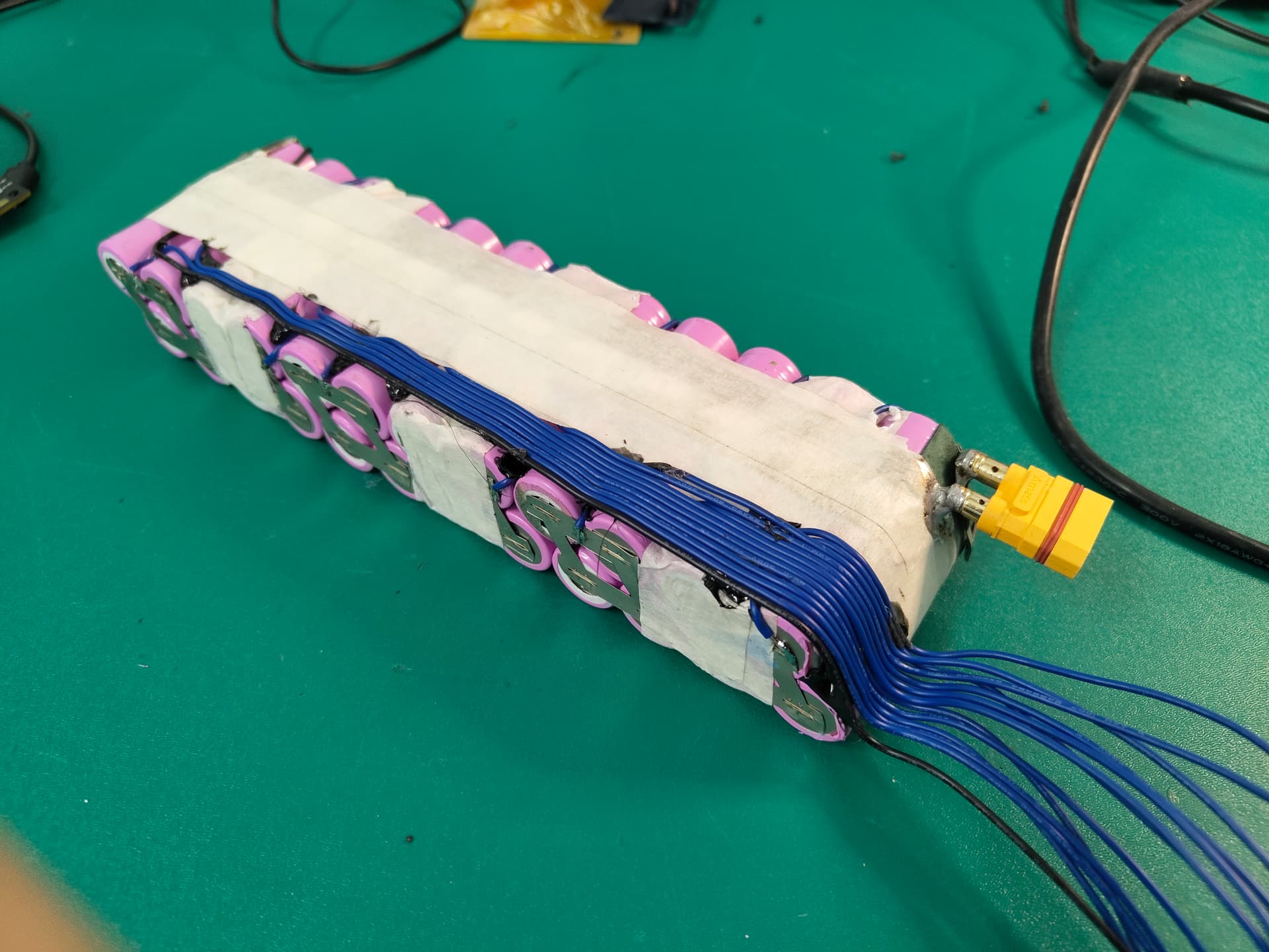
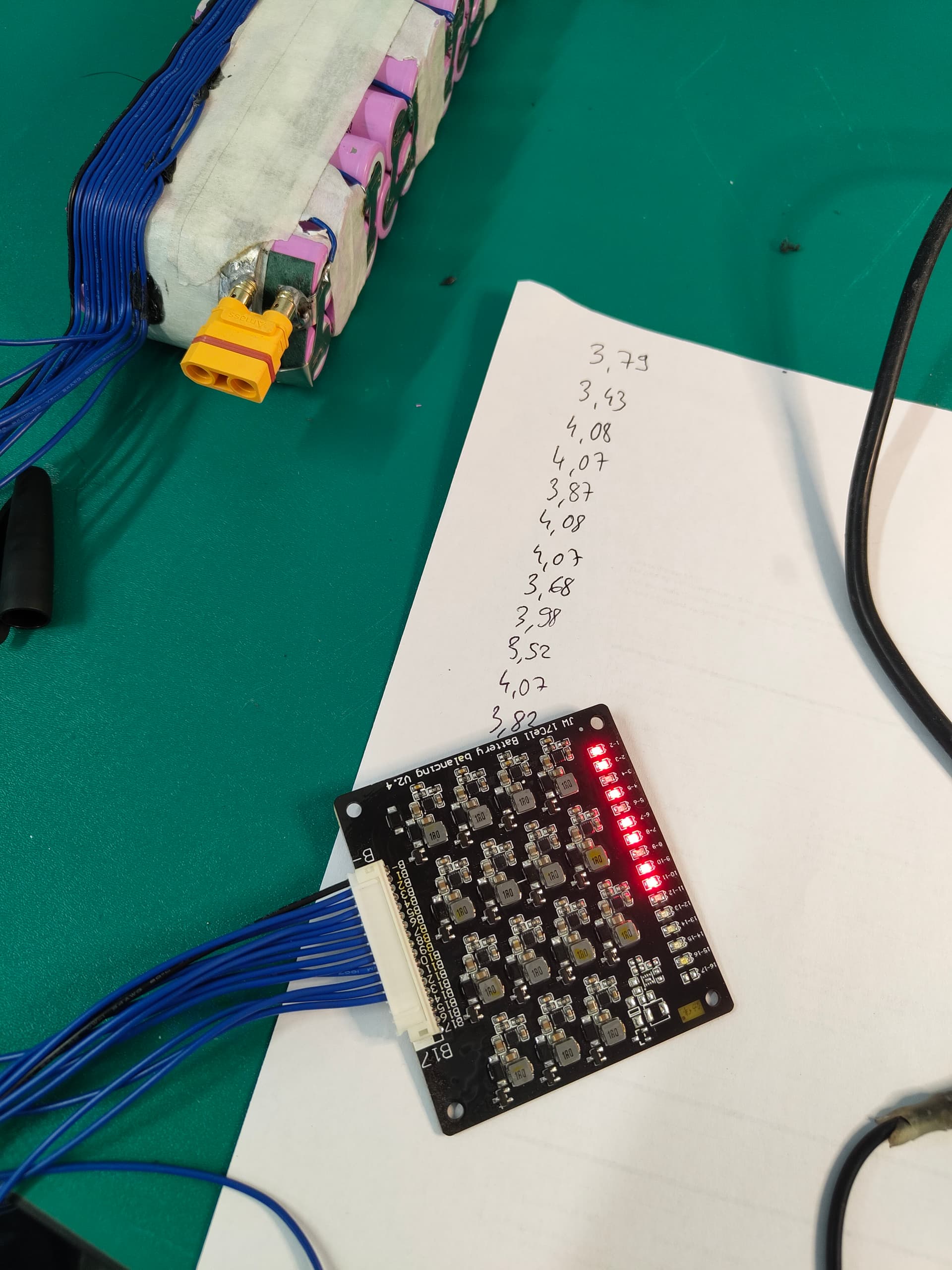
Tried to make the wiring clean, not my strongest asset. Cells voltage all over the place, I will check back in a few hours.
2 Likes
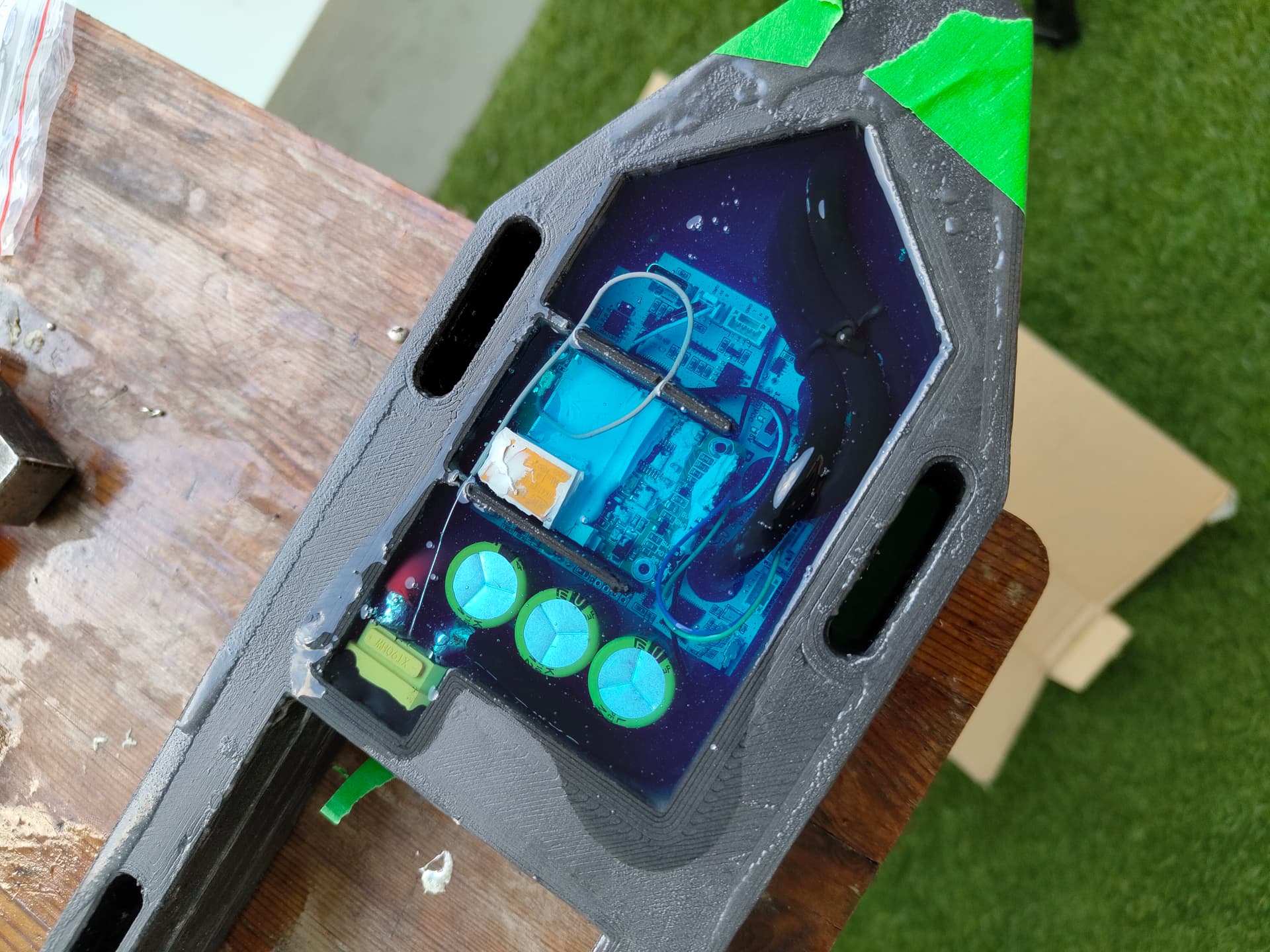
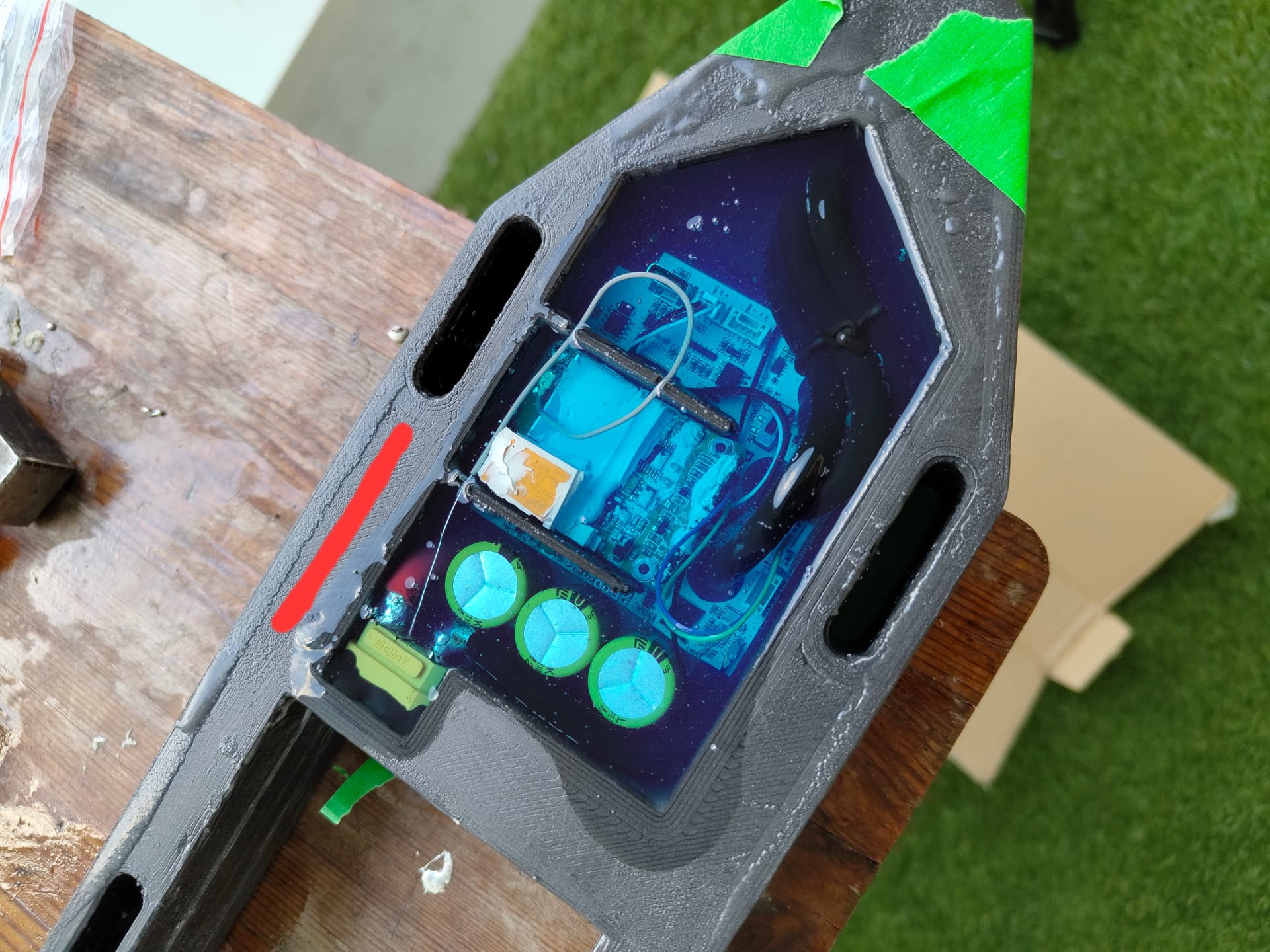
Wiring, tests and casting of the controller side is done.
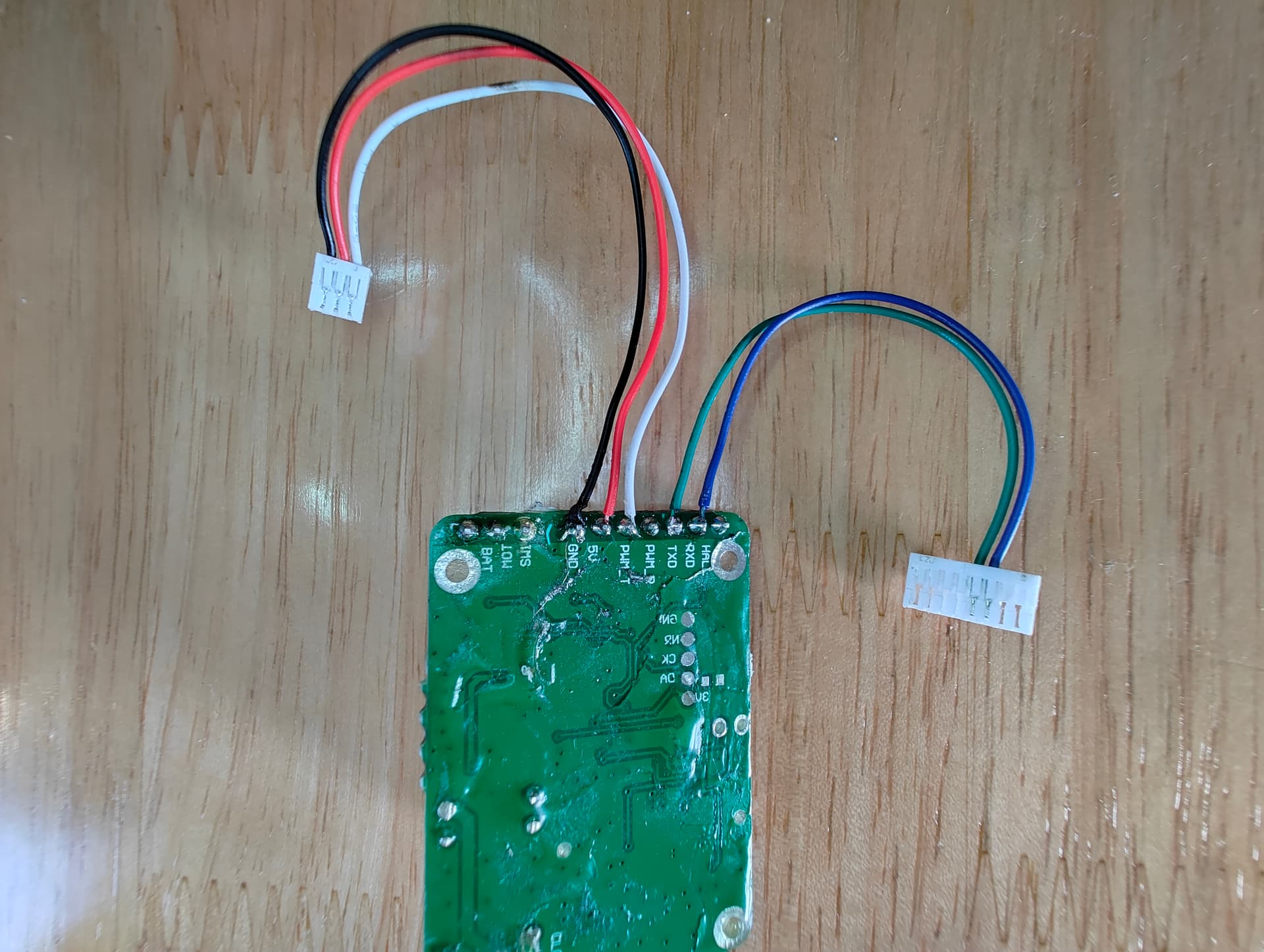
Tested uart, bluetooth and motor before casting.
For the antenna, went for as close as possible to the board surface.
Not conviced by the gel, it stays very soft, it will be a mess to handle with Sand and dirt.
Missing the pogo to finish it (battery side)
For motor setup, I went with max 40A battery, and 75A phase. The motor spin crazy fast in the air, I fear it will not reach an efficient RPM range in the water on the three blade.
Why so low current settings? Do you want to try the limits?
2p 30q is 30A max, 40 is already pushing it.
The vesc gives you a pretty good idea of the saturation current during the auto detect, and for the maytech it was giving me 65A. (Rms/peak is never so clear to me on vesc)
On my previous setup, I could start with a 1050cm2 foil and this board, with 65A batt under 7s, or a max of about 1600w. 40A under 12s is the same power. I used much higher phase currents then, I will see if it helps or is needed on 12s.
With BT, it will be very easy to change on the fly.
As for the gel, I think it’s worth providing a lid.
2 Likes
I read that the vesc current equals the current vector length - which i interpret to being rms, not peak. I think your phase current is too low but we’ll see🤞
1 Like
Did the cast, with extra space to wire the pogo later.
Used 170gr of epoxy, more than I though.
The battery box should be open on the top and not the rear. It will be much easier to cast, and to print.
First test went OK, but the Magic gel was sweeping all over the place, and providing zero structural strength.
Damaged a cap due to the xt90 of the controller coming loose.
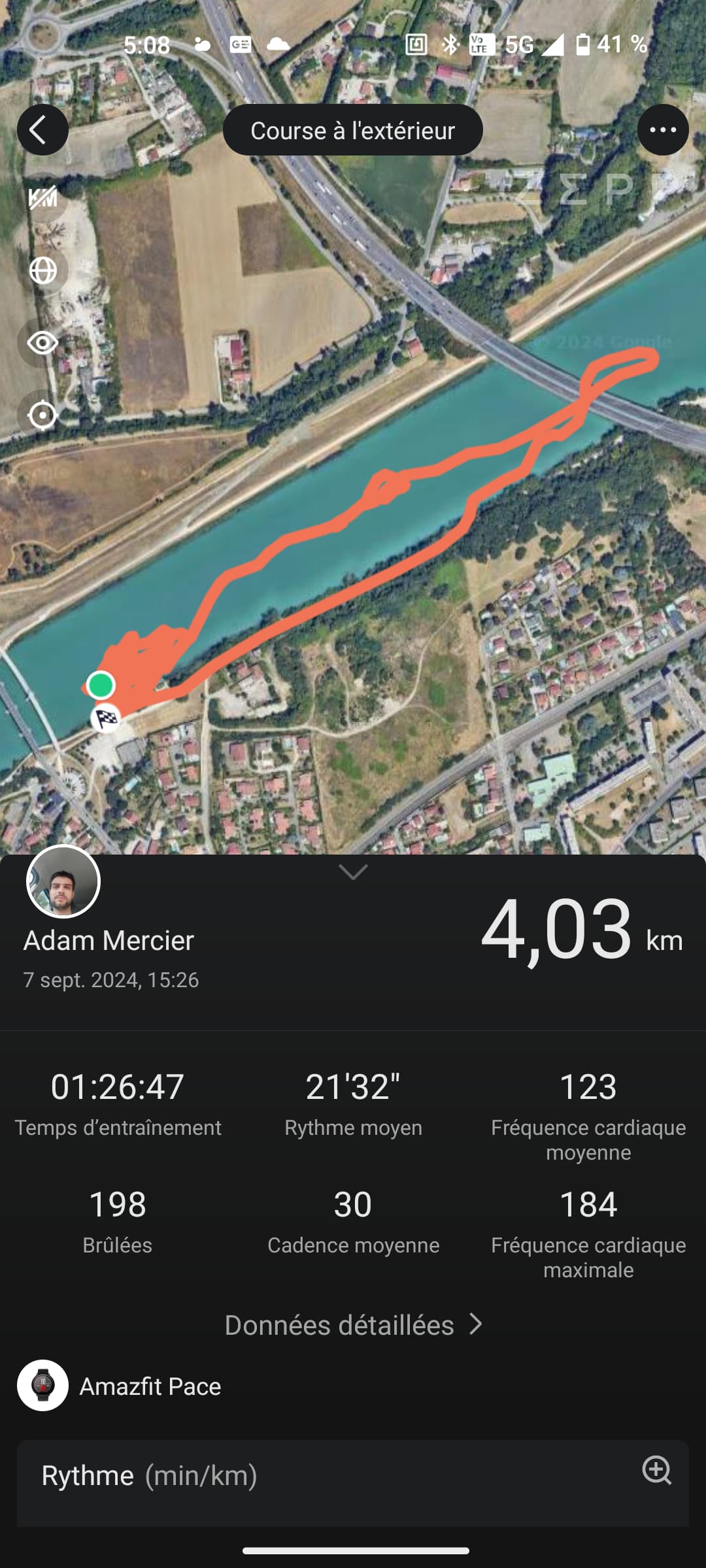
Signal IS very Bad, I could only start with my arm under the water close to the box .
Managed two starts, then I could downind motor off. That was quite cool as the weight and balance was great.
2 Likes
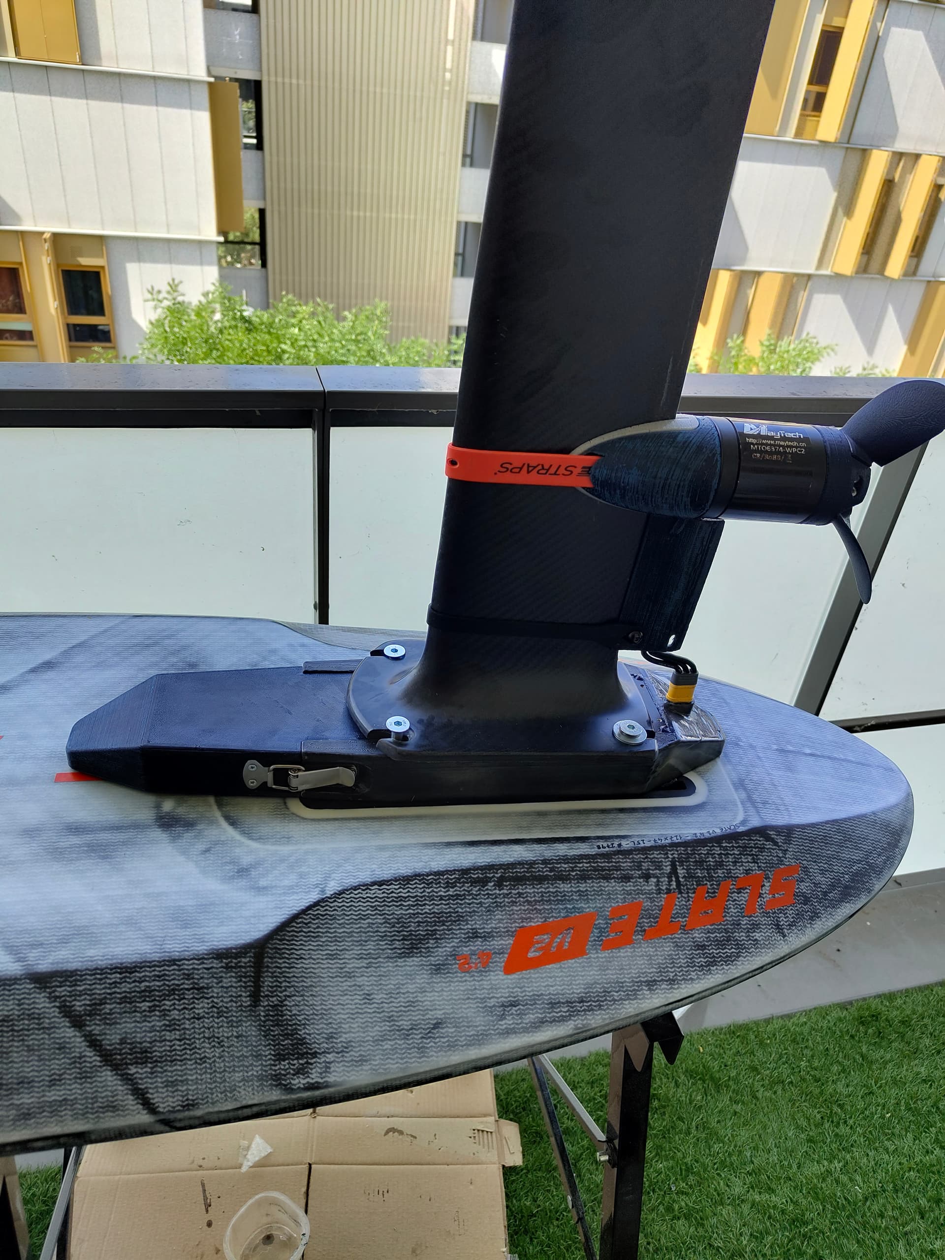
What version of Maytech did you use? My V3 has great connectivity, better than the Vx3 Pro. Is the board fiberglass or carbon?
1 Like
Full carbone board and as far as I know, v2 remote.
Then it doesn’t surprise me. My carbon board, for example, completely blocks the signal and only an external antenna helps.
1 Like
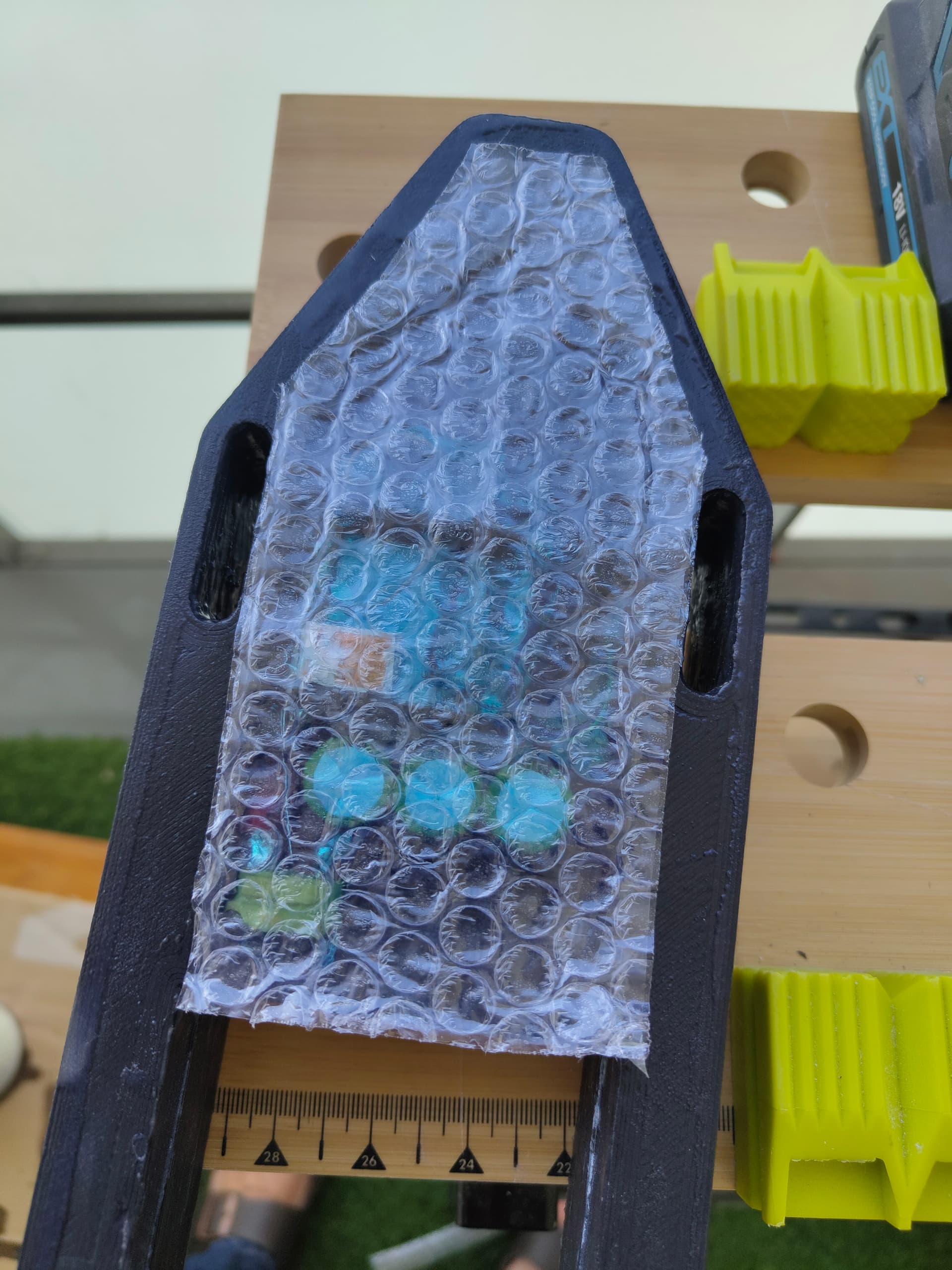
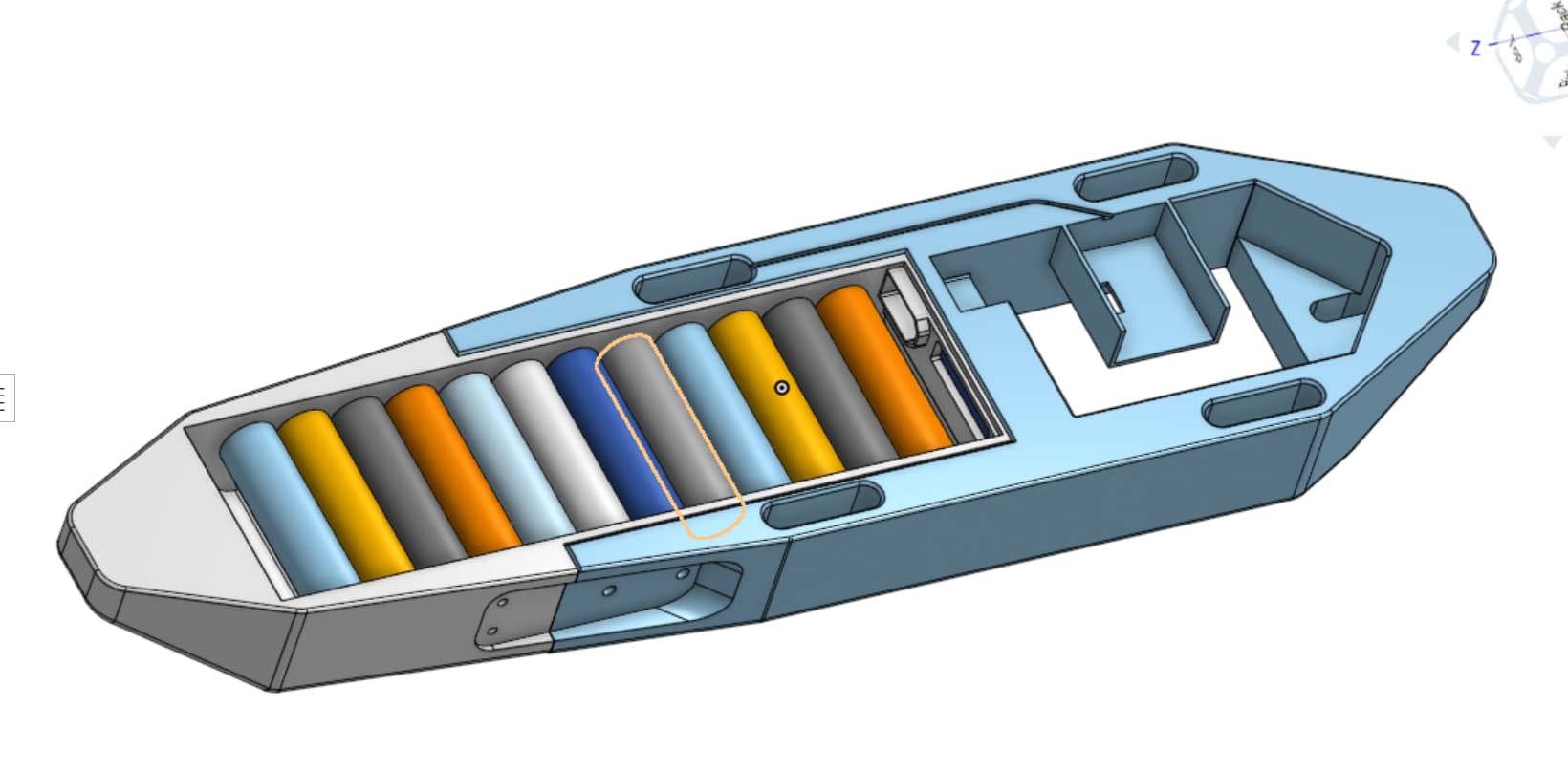
If you don’t want to mess around with an external antenna, try placing the antenna here and filling the track itself with foam.
2 Likes
Trying to keep the model up to date with my findings.
Top cast for the battery, antenna channel, changed the cut location between battery and controller to prevent the latch from bending due to the lack of support.
Removed all gel, now casting in epoxy
@rttn thanks for the tip, I did a channel to try it where you recommended.
1 Like
My electronics is fully waterproof with epoxy enamel only. Applied with brush after I thinned the epoxy. Nice to be able to replace a pcb at the time when they break down. If it helps.
1 Like
Please elaborate, can you put a picture, what did you applied the enamel epoxy to?
And you didn’t fill it with epoxy ?
With what did you glue the parts such as to be able to disassemble?
What enamel epoxy and what solvent?
1 Like