Hey everyone!
First of all thanks for the amazing work, really a great design!
Im quite new to this, im an event technician familiar with electronics, building my own lamp fixtures and large scale LED installations but so far never worked with motors.
I would have liked to follow your build but some parts are not available right now it seems. Also i found this more complex than the Flipsky route seems.
I ordered:
Flipsky 6384 Motor
Flipsky Remote
Flipsky Waterproof ESC
Flipsky Bluetooth UART
P45B 21700 Cells
an external BMS
a battery charger
I took some time to look into your design and while im waiting for my orders to arrive i started to redesign some parts of the CAD also because it wouldnt had fit otherwise:
Summary of what i changed so far:
the dimensions of the Controller Compartment to fit the Flipsky ESC
i added a second part to house the Bluetooth UART Module and the Waterproofing potting for it
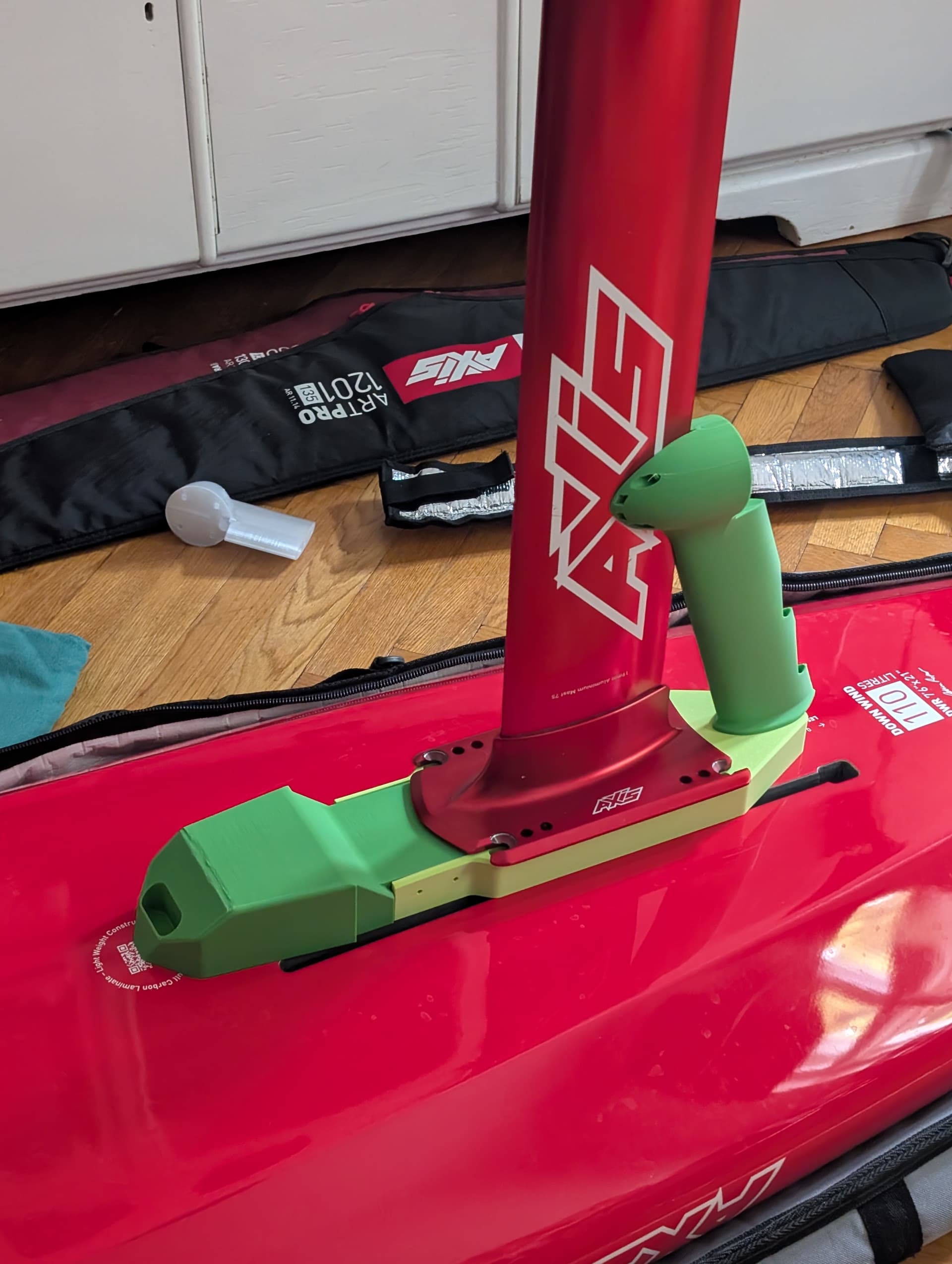
made the compartment as wide as my AXIS Mast
i added a extra pogo pin out for the USB of the ESC
modified the way the mast is attached
experimented with a new higher motor mount connected to the mast
(i liked the idea of this assis being in one part but as i moved the motor higher i thought its better to attach it to the mast as well)
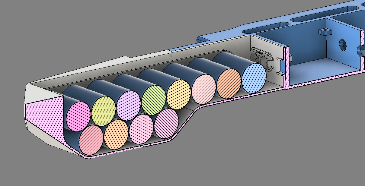
changed battery layout to make it more compact (moved 4 batteries to a second row)
modified the front to make it more hydrodynamic
added new lockable high tension force tensioning levers
While i design a lot of things, also a lot of electronics, i really dont have any experience with battery building or with high power motors. If you see some bad ideas happening on my side please feel free to let me know!
I already printed some prototypes of this. Not the newest version update though.
Some questions i have:
About the battery, i did some research and found that 2K Polyurethan Potting might be the best material to waterproof the batteries, is this okay?
Did you epoxy the XT90 into the chassis before waterproofing the batteries?
Why did you use a busbar to route the power instead of a cable? Isnt a rigid element possibly more likely to damage the batteries?
Thanks for any hints or comments about my ideas, ill keep you updated
PS: Seems like i cant add pictures as im a new user here.
Hi, some images of your design would be helpful to determine if there are any bad ideas. Not sure when you will be able to donthat as a new user though.
Regarding the flipsky esc. I could fit a 75100 in the original design. Regarding external BMS for charging. It is a pssoible way to build your own charger, but many use simply a RC charger. For example the iCharger x12.
Yes, PU should be better for potting the battery. Let us know your experience with that I shied away from it for my first build due to the lack of experience. The epoxy works great until now though.
The busbar in my case is just a folded 30mm (or 50mm? ) x 0.3mm copper strip. Compared to a cable it is low profile. An euqivalent cable would not fit.
When you make the housing wider and you do not want to mount the motor on the housing, you could place the controller width-wise and make that compartment shorter. Then you can put the battery deeper under the mast. Basically like FD.
Loocking good, wouldn‘t it be hydrodynamically more optimised to put the 4 cells of the top row in front and make the battery a bit longer but keep it flat?
I would keep those cells in case of 12s1p in a single row for two reasons:
you are adding drag in the water with your configuration
the batteries help with counter balancing the weight of the housing and motor behind the mast. The shorter the battery the less counter balance you have. I have found that 12 cells are not able to completely counter balance the weight of the motor. Maybe a 12s2p config does and that’s a config where a second row makes totally sense.
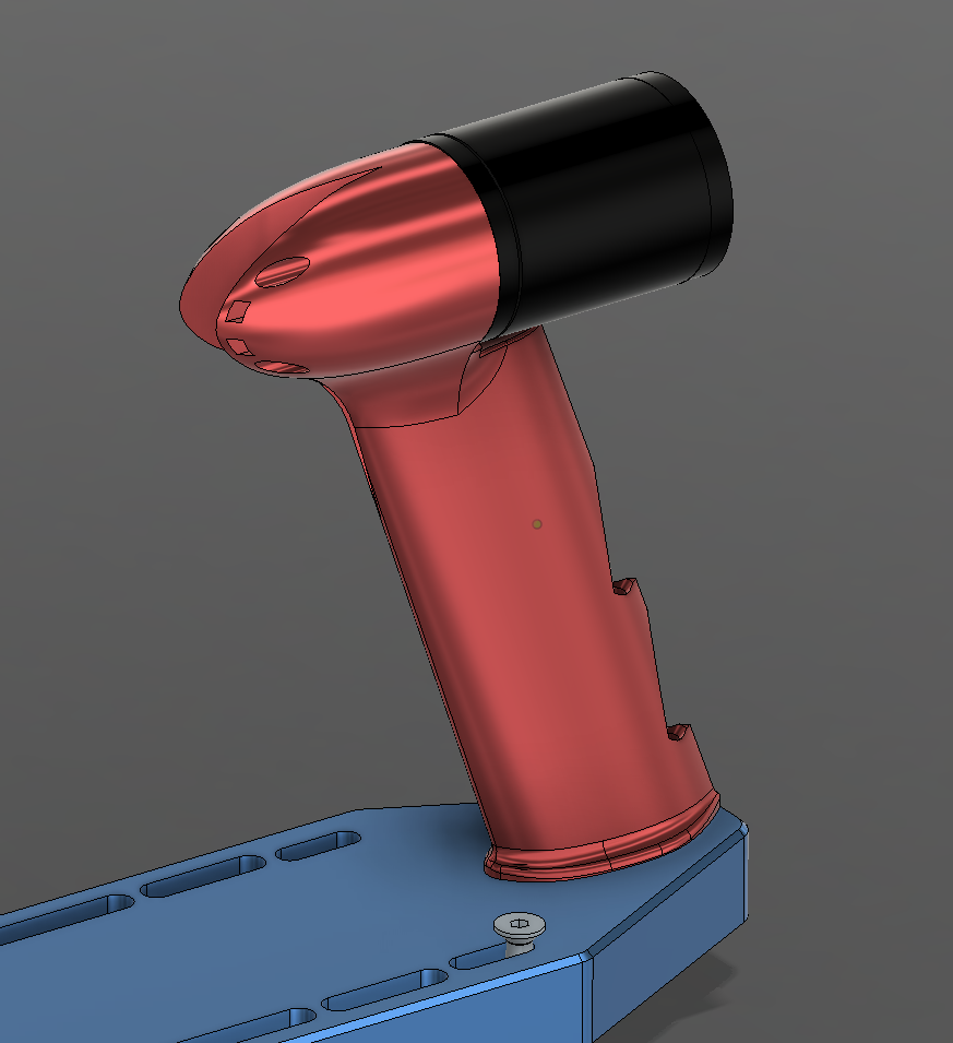
Your motor cable guide is also adding a lot of drag. If you want to attach the motor on the mast with cable ties (kind of a permanent attachment) you can either:
tape the motor cable to the mast (would choose this option for the beginning and optimize later)
guide the motor cable internally through the mast (best option regarding drag, but you need to modify the mast)
create a smaller cable guide along the mast (there are many examples of it)
Yes, this makes all total sense to me! My idea was that it would be easier to asemble and disassemble. To have it in one part which i can just get off when the battery is dead to continue pumping without. But i realize that drag is a huge factor so ill try to come up with a more suitable design. Id love to realize this somewhat modular though to test different setups with the same motor. Also the battery layout ill keep simple due to the drag. Guess i was a bit overmotivated to design some new features, lets keep it simple
I can not share it directly but file should be available online somewhere by now.
System is smooth, Ti blades works , did not test the spare alu prop to compare. I printed a second battery box and will assemble a pack with bak 50D or lishen 50pt cells.
I had a charger failure while on holidays, so I bought a new power supply that does 12A, for 20-30 min charges
I also had problems with my power supplies. I found a 16.5A power supply for gaming laptops with an xt60 port, so it connects without an adapter cable to the iCharger
After many session on my DW Board I tried the 4’2" prone board with the Veloce H XXL today again. This time with the FD prop. I was doing flat water starts and had absolutely no problems getting up on to the board.
With that prone board throttle and pitch management become way more important. On touch downs the board more likely sinks and with that high positioned prop those touch downs happen a lot to me at the moment.
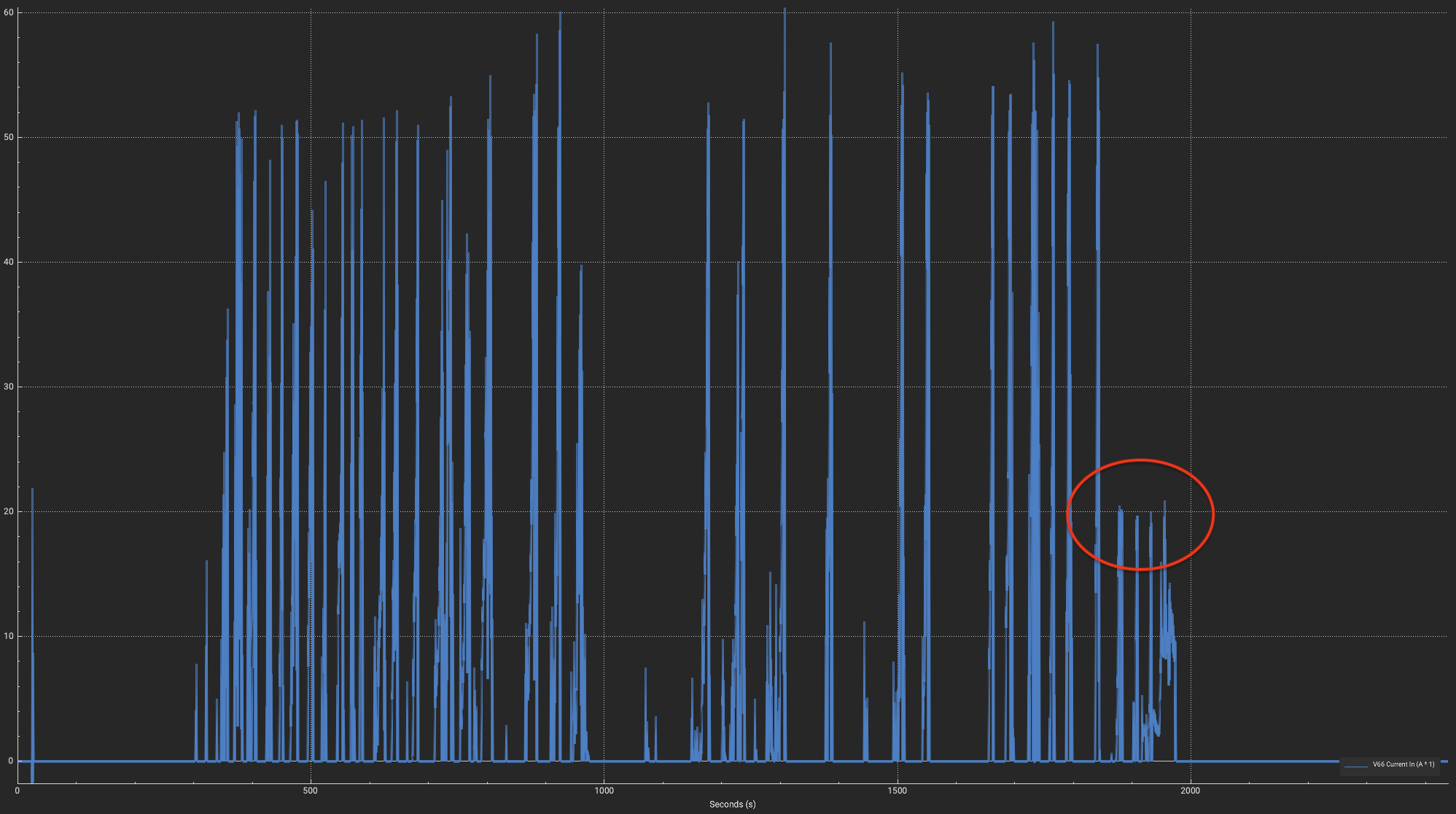
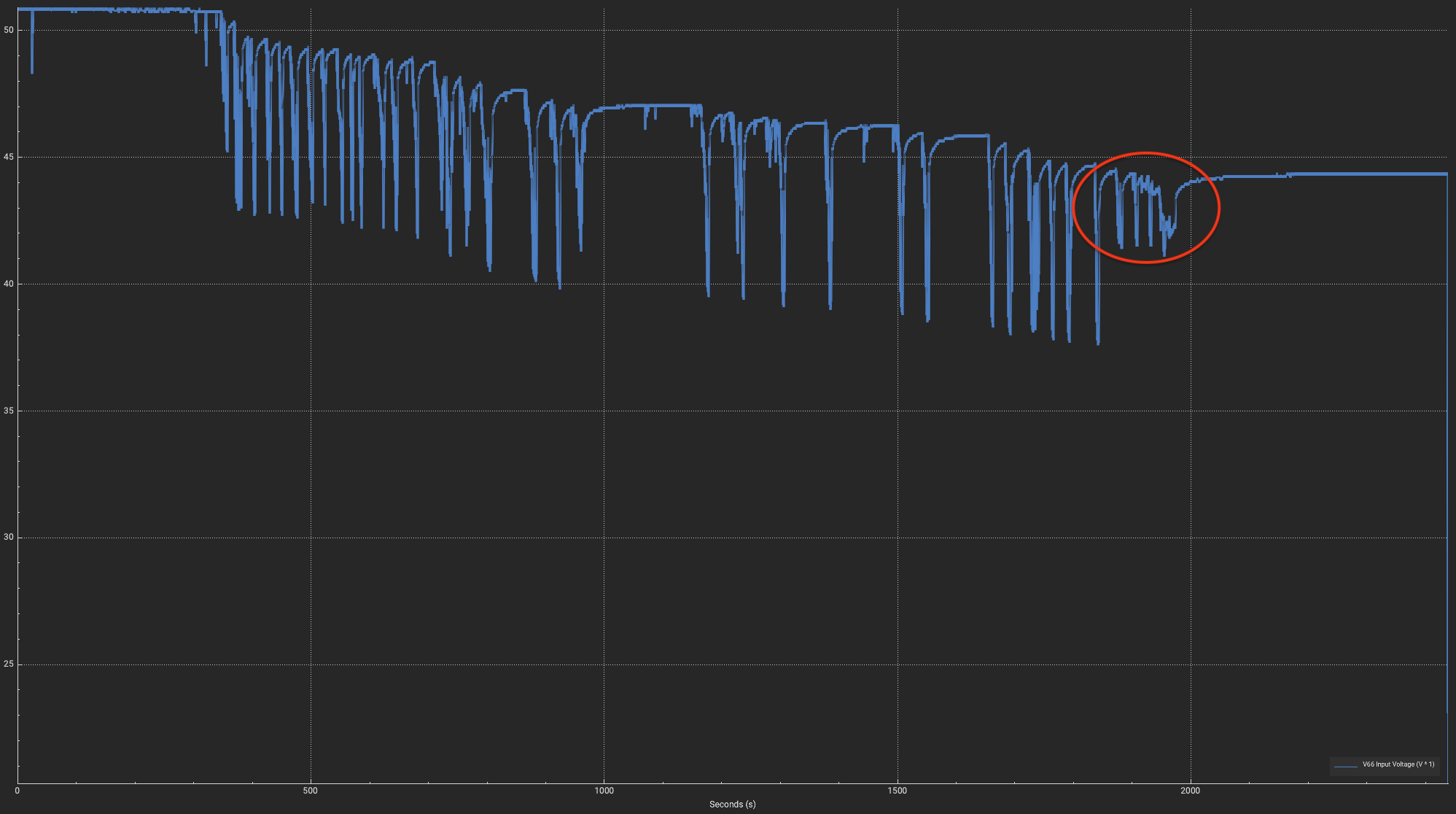
Also it seems like the battery got to its limits. I took a look at the logs and I was not dipping into the voltage cut off (start @35V, end @32V). At one point it only delivered max 20A while being at 44.4V resting voltage. This session I was feeling some heat when touching the pack. Probably the battery overheated. So I decided to end the session.
With the DW Board I did not experience such heat and power losses.
Interestingly the battery amps peak way over the 45A limit I have set.
Edit:
Thought a while about it and do not think anymore it is a battery issue. The voltage drops are also significantly reduced. So I think the VESC did not request more amps even though I was on full throttle. Also that it always cuts at 20 amps is an evidence for a VESC issue. It might be a 75100 VESC issue related to the problems observed in this thread:
I think the time has come to replace this VESC. The Harry M VESC has already arrived and I am waiting for cable lugs.
It just needs to hold up until tomorrow as I will be wake thieving with friends
I will go on the water today and check if there are any fault codes. Unfortunately those do not get logged and there does not seem to be a setting to send them to the VESC Express for logging.
I have a vesc express and SDCard in my build, but did not manage to retreive data by wifi/bt so far and make a correct setup for auto logging. Need to look into it
It is not very easy. Some SD cards do not work. Then they have to be formatted correctly. You need to install a plugin on the vesc express where you need to setup correct IDs. On the vesc you then need to select the data points you want to pass to the express, but it is not named correctly, so you would never know. Then when everything is setup correctly it might still fail. So restart the VESC and voila, it works
Took me an hour or longer to figure it out with Claude haha
I can send some screenshots later of the setup in the VESC. Need to go on the water now
Ah aaand taking a look at logs of a real session does not work either via Bluetooth or Wifi because the download of the logs takes a couple of minutes even via USBC connection. Bluetooth and Wifi are so slow and unstable on the VESC Express that it just freezes while downloading. So always a mess with tearing up the Magic Gel and repairing it again to only connect via USB.
Found out that I did it wrong. In the manual they emphasize to connect via USB on the VESC when setting up logging. I was connected via WIFI which led to a couple of issues and ultimately to get it running I have installed the LogUI Plugin on the VESC Express instead on the VESC itself. It works this way but it logs only values that are available via CAN. When installing it on the VESC the local values get logged including “faults”. So I was complaining unnecessarily about this.
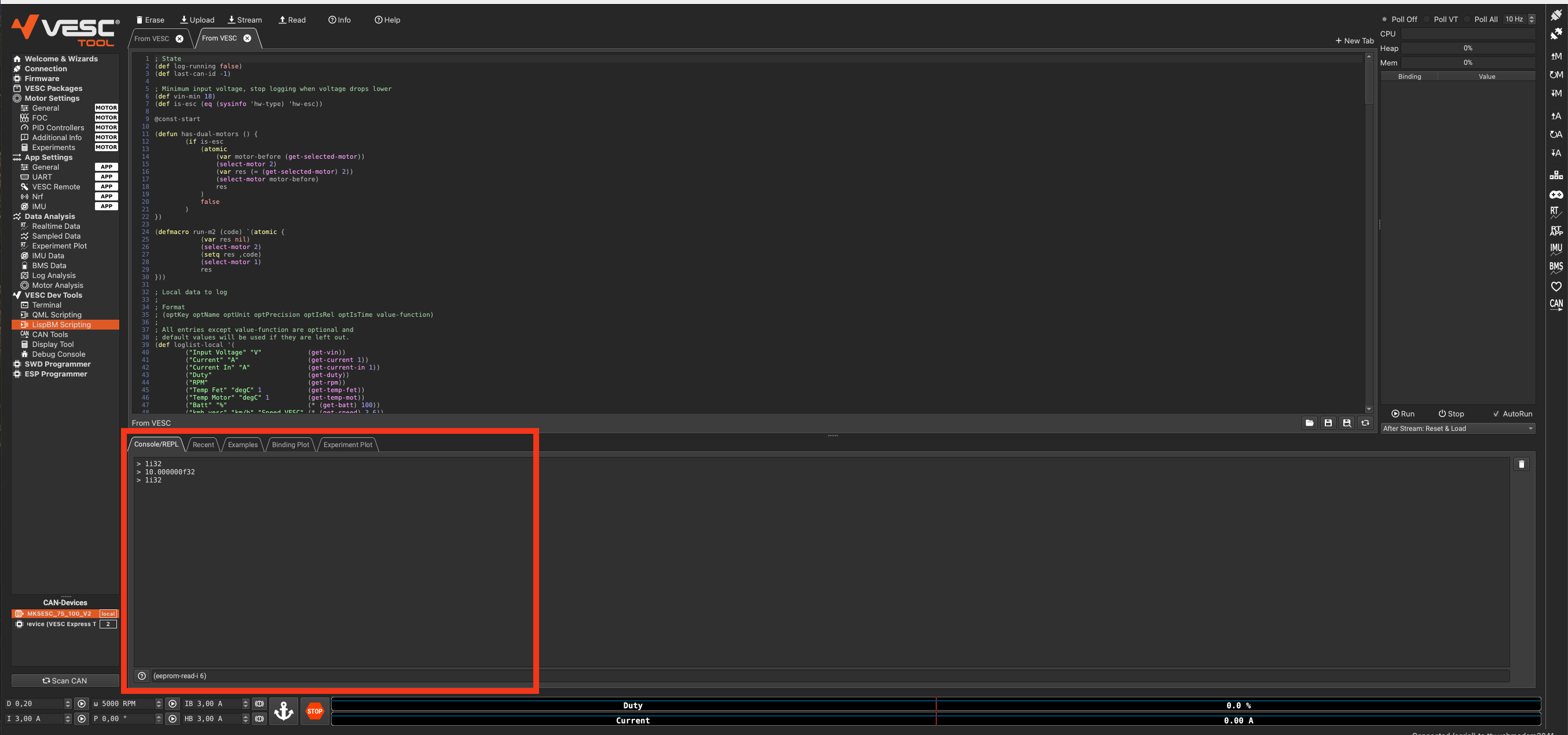
Anyway, I repeated the setup documented in the manual and it works now. But, there are some Bugs in the UI which make you believe that the chosen logging settings do not get saved to the config. I mean the settings from here:
When reconnecting or switching between VESC and VESC Express the form does not reflect the stored config values. In my example “CAN Values” and “Start logging at boot” become unchecked.
Luckily you can verify the values somewhere else. Go to “LispBM Scripting” and then at the bottom in “Console/REPL” you can print the values: