I’m in the process of designing a board that is roughly based on the 4’9" Lift board. I’m getting stuck on designing the interface between the board and the mast. From what I’ve seen, people generally use turtle boxes or plates. I have a Gong Alligator v2 mast, and I want to use it as a passive heatsink to cool the VESC, so I need a hole for the ESC to fit through, too. I was thinking about a 3/8" aluminum plate with a seal built into the board like a Flightboard. Does anyone happen to have any ideas on how to reinforce that area?
For the adapter plate (gong > Fliteboard) we used a 15mm thick aluminium plate.
The thickness was only needed for the “pocket” where the 3 phase wires go through from the motor to the VESC as they needed to be covered with potting for waterproofing.
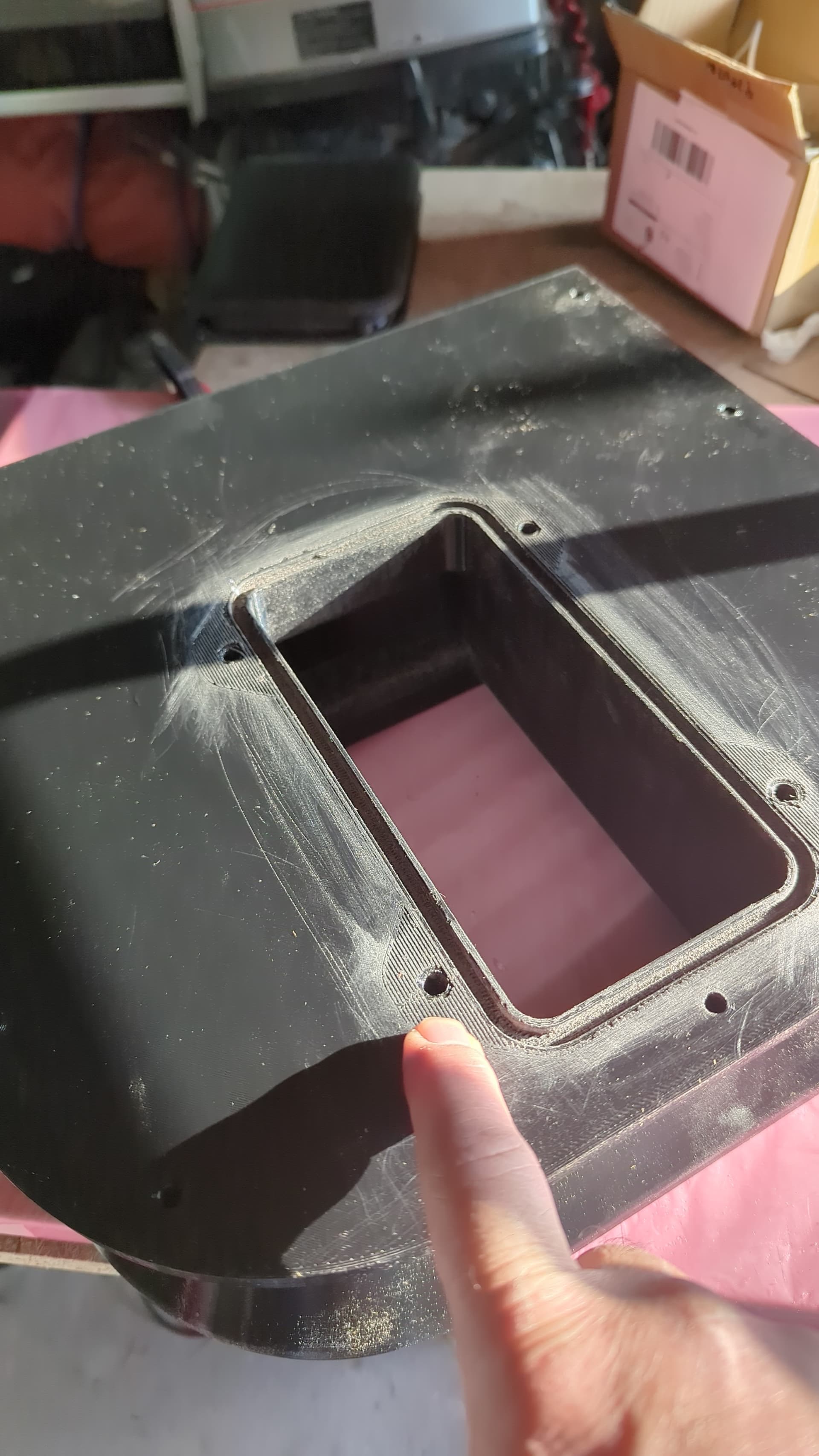
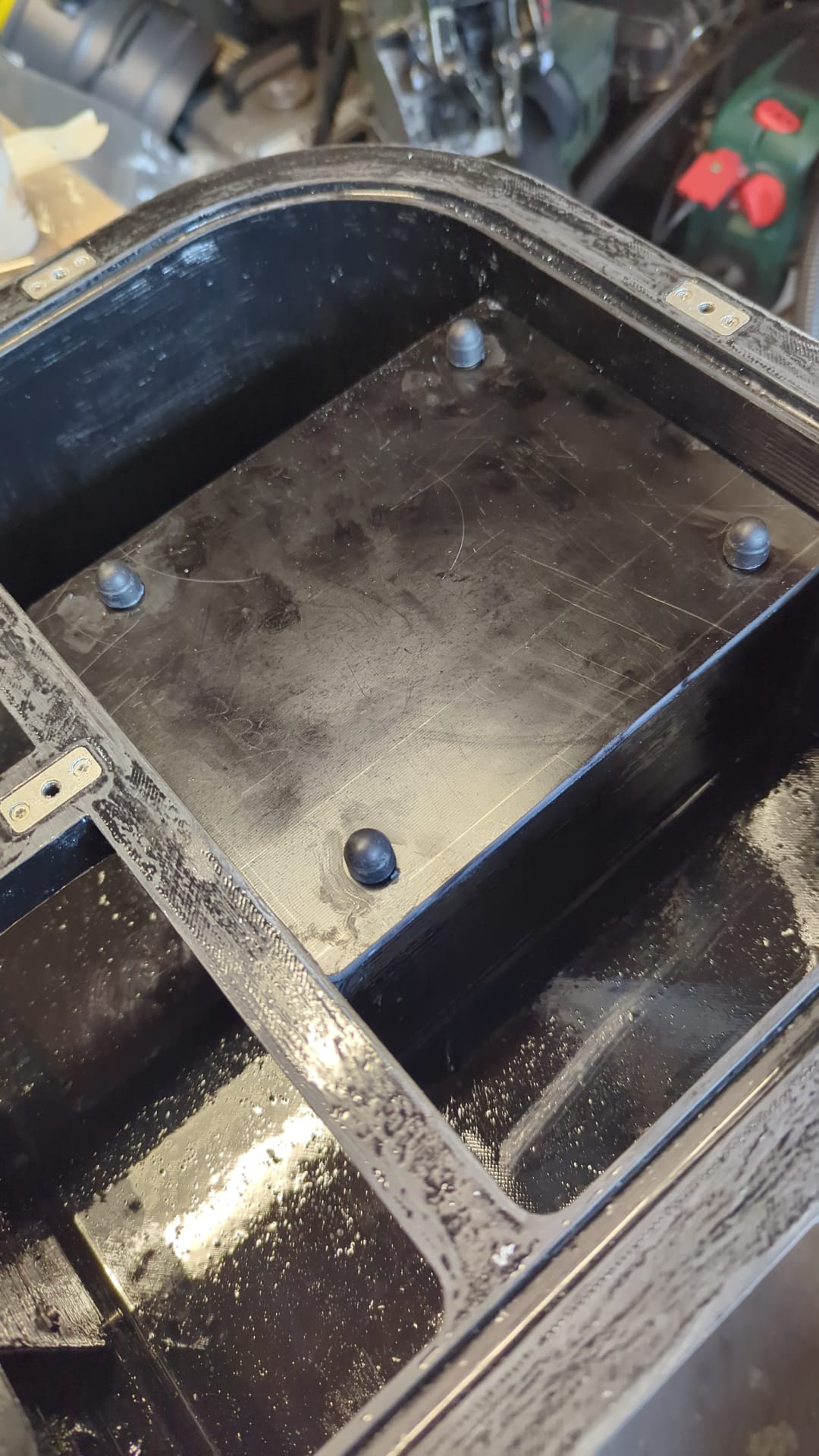
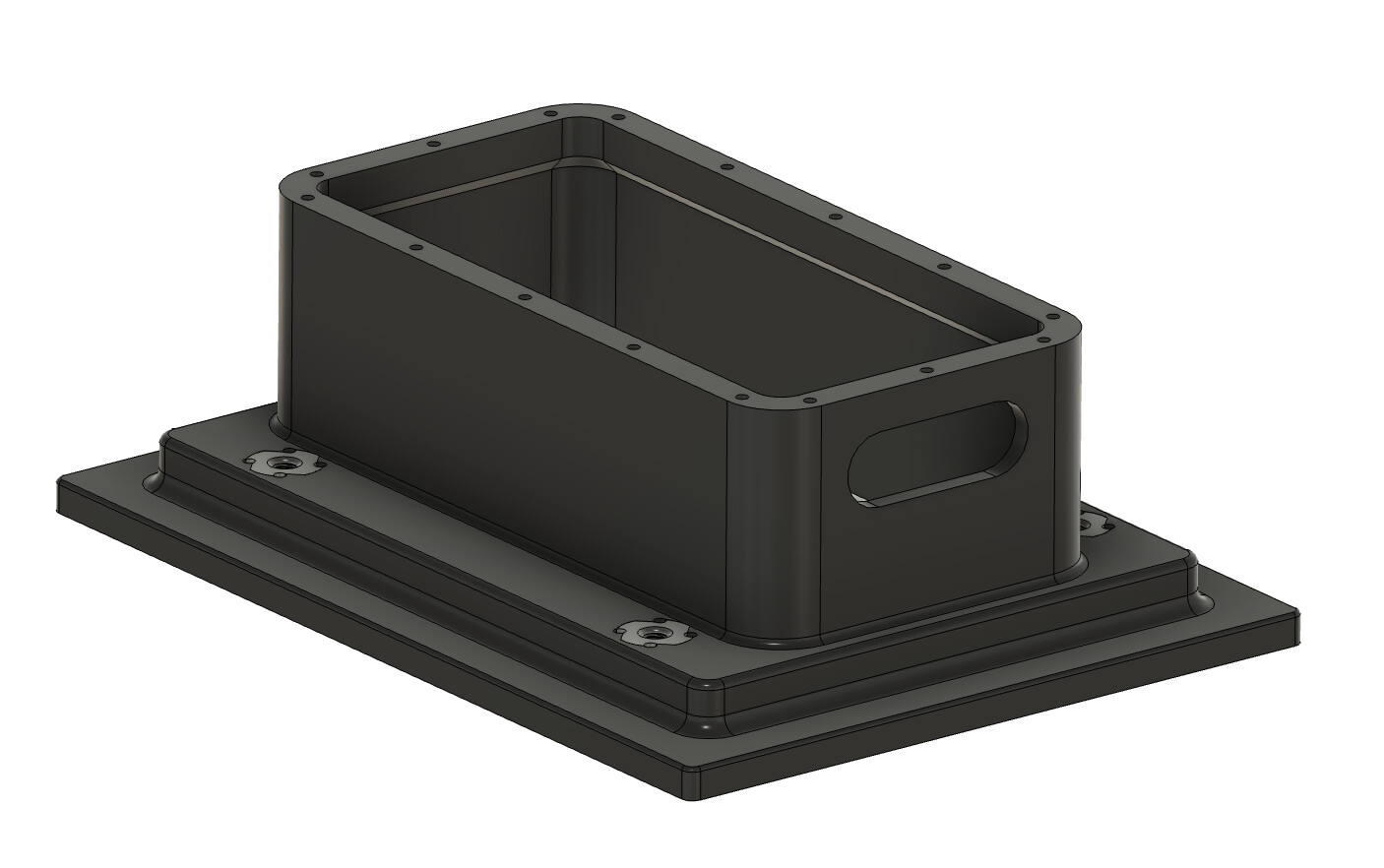
So, after a long pause and a bit of recovery from life, I’ve finally gotten the all-important spousal approval to make headway on this project. I’m going to 3D print the fliteboard-style interface box. After doing some tests, I’ve gone with stainless tee nuts and backcoating them with a layer of glass to lock them in, similar to how I do snowboards. I’m using the tee nuts for more thread engagement as my snowboard nuts are only 5.5mm.
Doing the same basic setup as flite does, but I’m debating on casting it in a task series urethane, or printing in ABS/PPA-CF or similar. I saw a video of a guy who hit the ground hard and ripped his out, revealing that there really isn’t much to it, and I’m way overthinking it. Link to video.
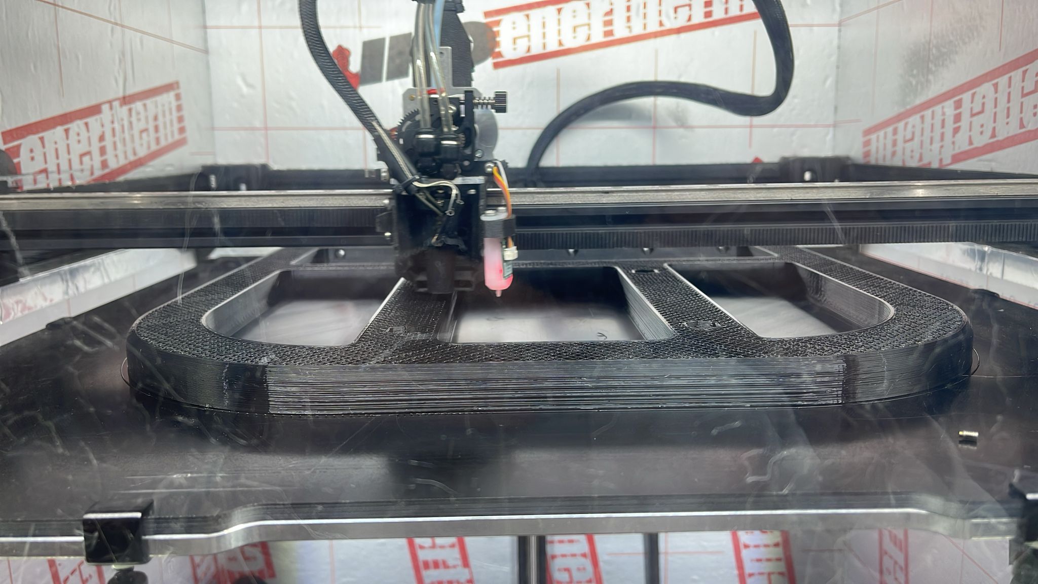
Test piece fresh off the printer, I’ll need to wait for the inserts to arrive from McMaster before making the final one. I’m thinking of inserting some 3mm rods as structural reinforcements in the design for shearing loads along the layer lines. I’m not thrilled about the orientation of the layer lines and the forces that will be acting upon it. At 100% infll it would work fine, but man, it would be heavy. Needs some revision.
I will add a full or half dovetail oring slot to the bottom. I’m trying to figure out how to get the surface finish smooth enough for an o-ring to seal. According to the Parker Oring manual, I’m pretty limited in options for orings of this size.
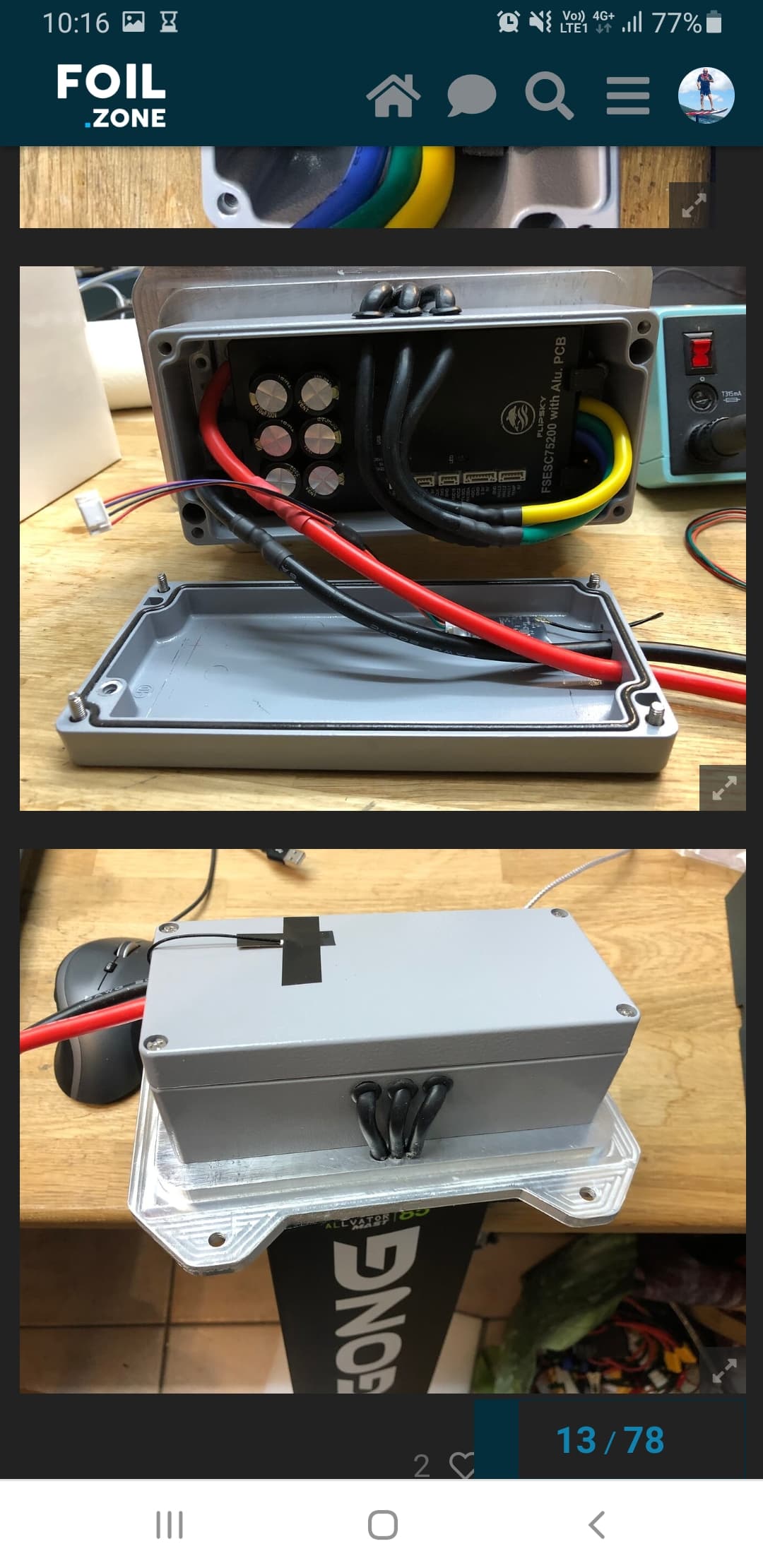
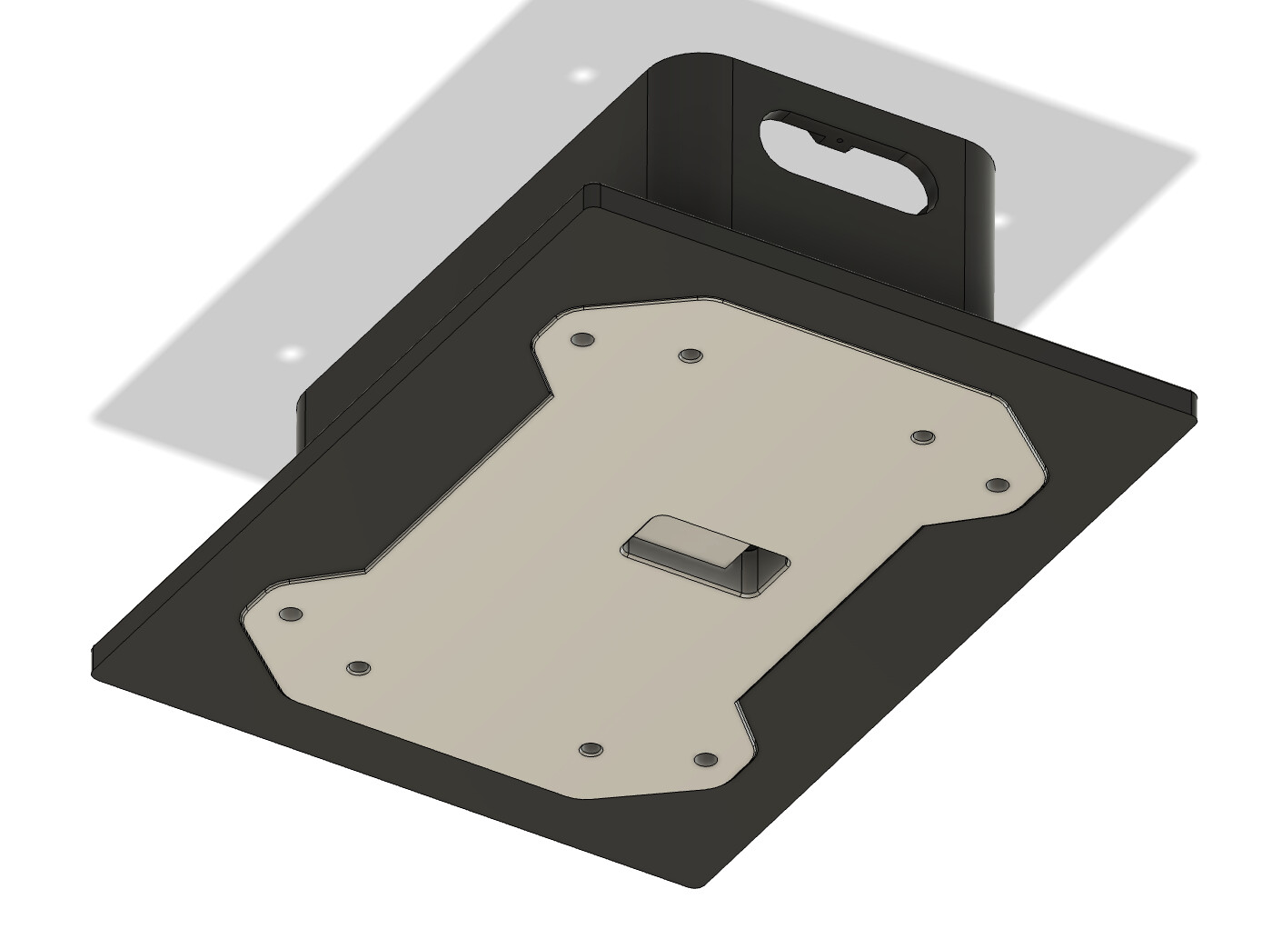
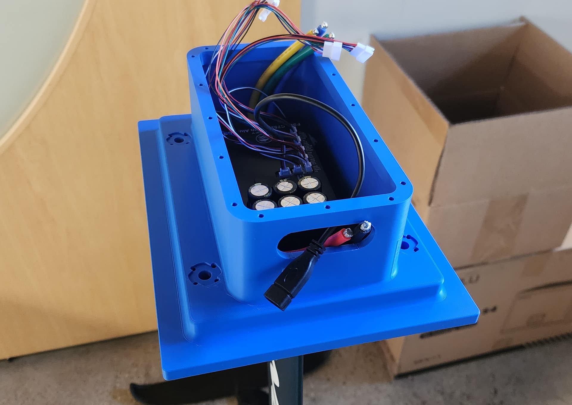
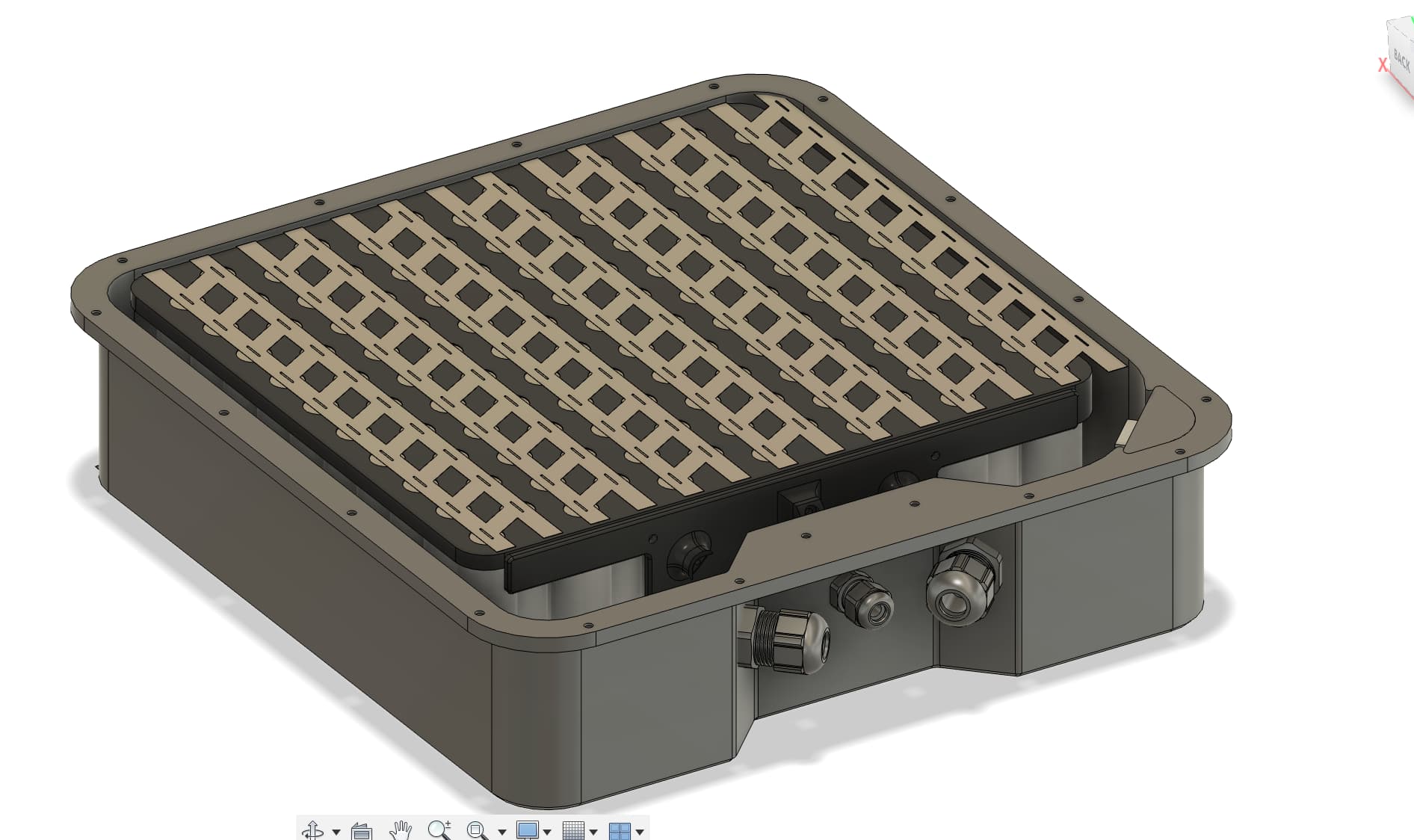
Some minor updates, printed out more pieces, and figured I would add a power button and use a Flipsky 75200 v2 for the phase shunts. From what I understand, that allows for the silent HFI operation mode. I’m also thinking about the power and CANBUS connections. I need to work out the physical spacing required to make all of that fit on the front of the box without compromising structural integrity. I also need to figure out how thick the hatch should be as I need to make sure I have clearance to fit the battery. I plan on putting the cam locking shafts outside of the sealed area. Still working out how to make the seal and would love some opinions.
As I wait on shipping, I want to get foam cut soon, probably will do a test board in XPS for a quick and dirty fit test. Still need to figure out the battery enclosure itself and the amount of actual space needed.
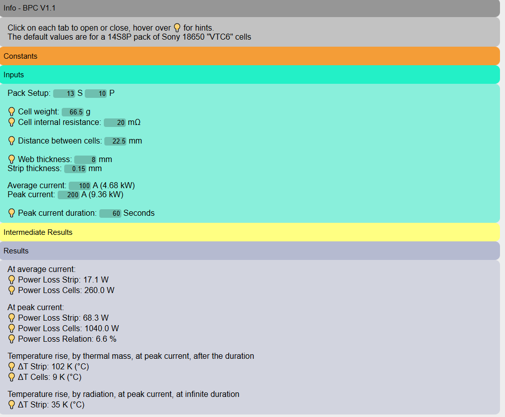
Tried to assemble the pack tonight, looks like my prepunched nickel strip was designed for touching cells, so a new order has been placed. I ran the numbers through Ludwig’s calculator and found that I wouldn’t get extreme heating. Since I plan on making this out of ASA or ABS, I’m trying to keep the peak heating under 80 °C, as I won’t have fish paper rings on this. However, at 200 amps and 60 seconds, I seem to reach 104 °C. Anyone with experience who can chime in, because that seems like a huge increase for what is supposed to be 68.3 watts of loss.
For 200A and 60S you are better off looking at the value from the 2nd calculation method (all the way at the bottom, 35k in your case)
Please also note: All those values are relative, above ambient. So dT=102K, at ambient 30°C on a warm day, would be 132°C on the strip. But as said, for durations >10 seconds, the other value is more realistic, resulting in 30°C + 35K = 65°C strip
Thanks, Ludwig, that makes much more sense to me. I don’t really want to try and calculate the thermal dissipation of a box in a foam box, so I’ll just say it’s super good enough. The 200 amp use case is a winter application, so dT won’t be too bad.
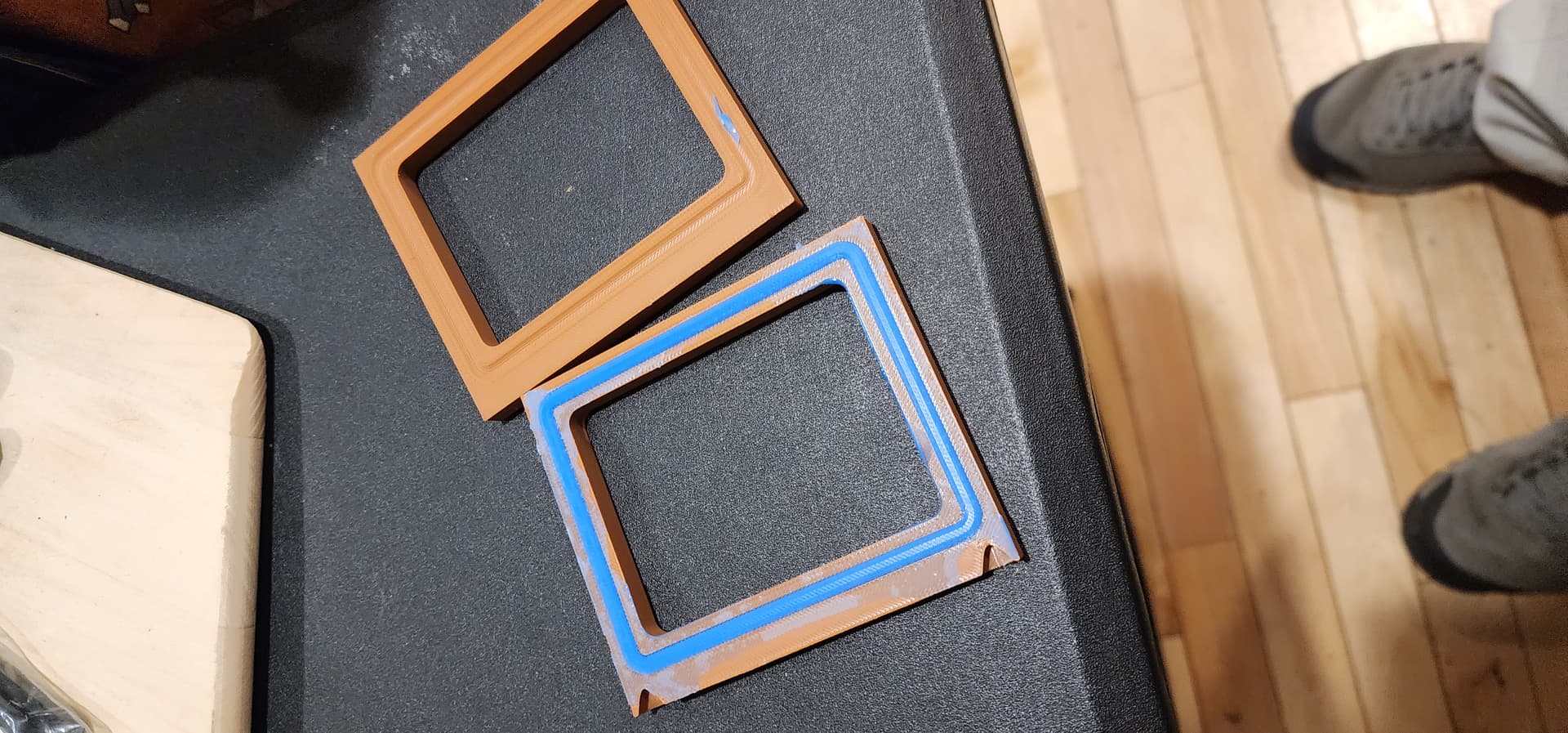
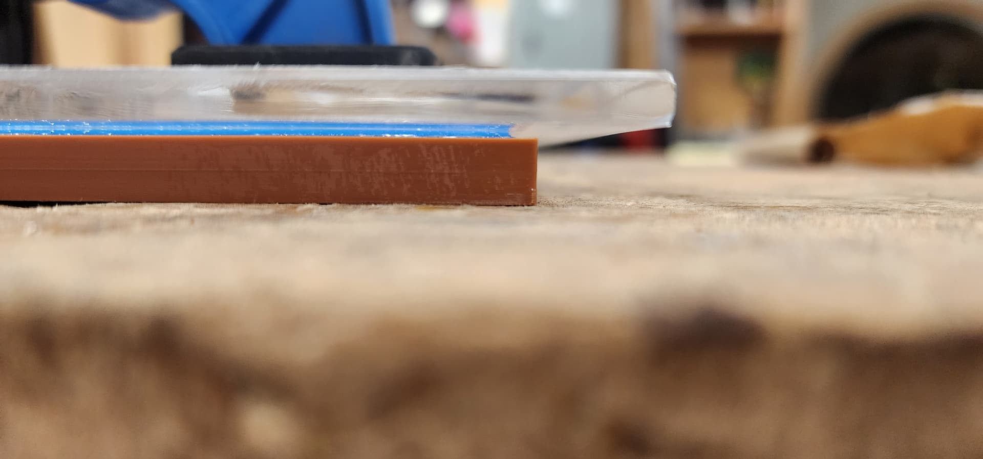
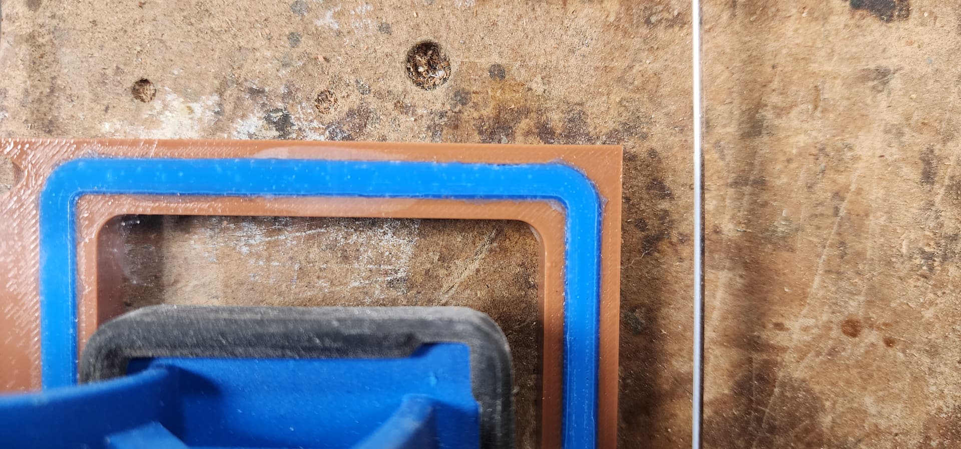
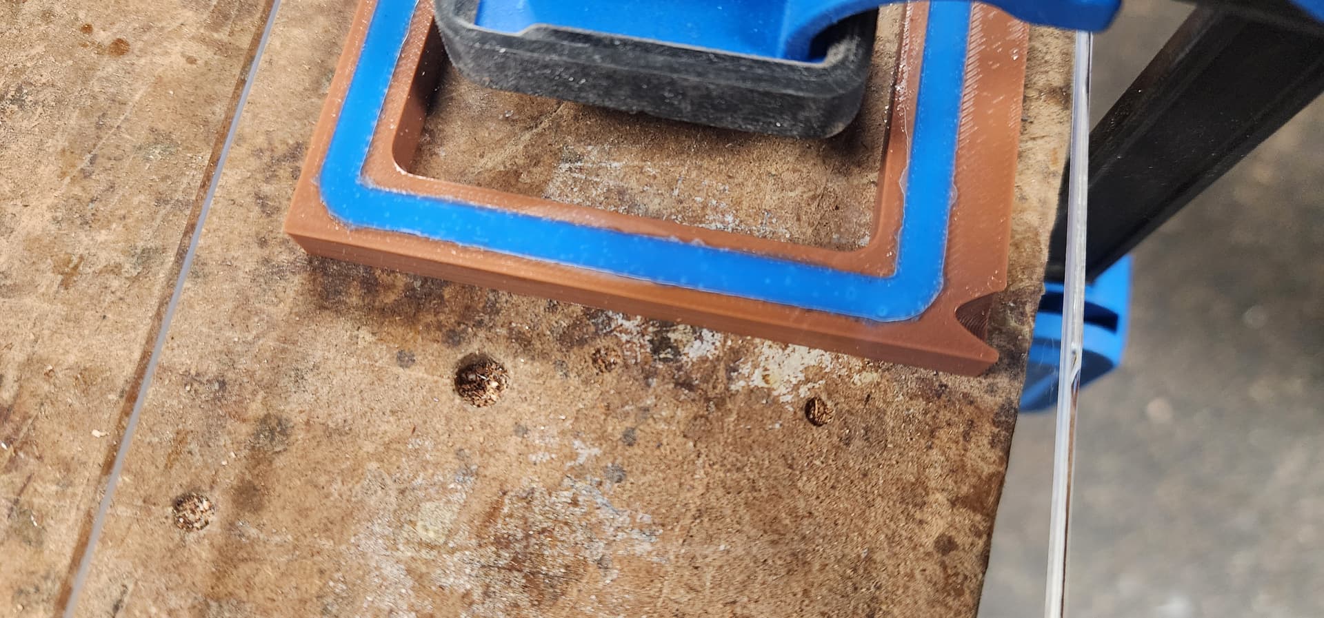
I’m still messing with seal geometry. In doing so, I decided to make some test pieces for a MoldStar 30 seal. My thought was that the rougher surface on the bottom of the turtle box won’t seal well, so I used the geometry from the Parker O-ring manual to create a dovetail slot. Then I cast MoldStar 30 (had it on hand already) into a test mold, which almost matched the seal, but with a little free area at the top to absorb the deformation. This turned out to be not enough room; I should have greatly reduced the lower cross-sectional area. Based on my test results, the seal doesn’t have enough area for deformation to occur and allow the mating surfaces to meet. This probably isn’t worth the squeeze, literally in this case, as I’m hoping the orings I ordered arrive soon. This method would also require a much smoother mold to cast into. However, I could see this being useful on hatch covers, so I may revisit it once I get the bottom interface done.
So orings came in and they fit the dovetail slots perfectly. I tried to enable ironing, which worked great on these PLA testers, but I haven’t tried it with the PPA-CF that the mastbox will be made from. Right now, I’m diverting my attention to the battery pack as most of those components have arrived.
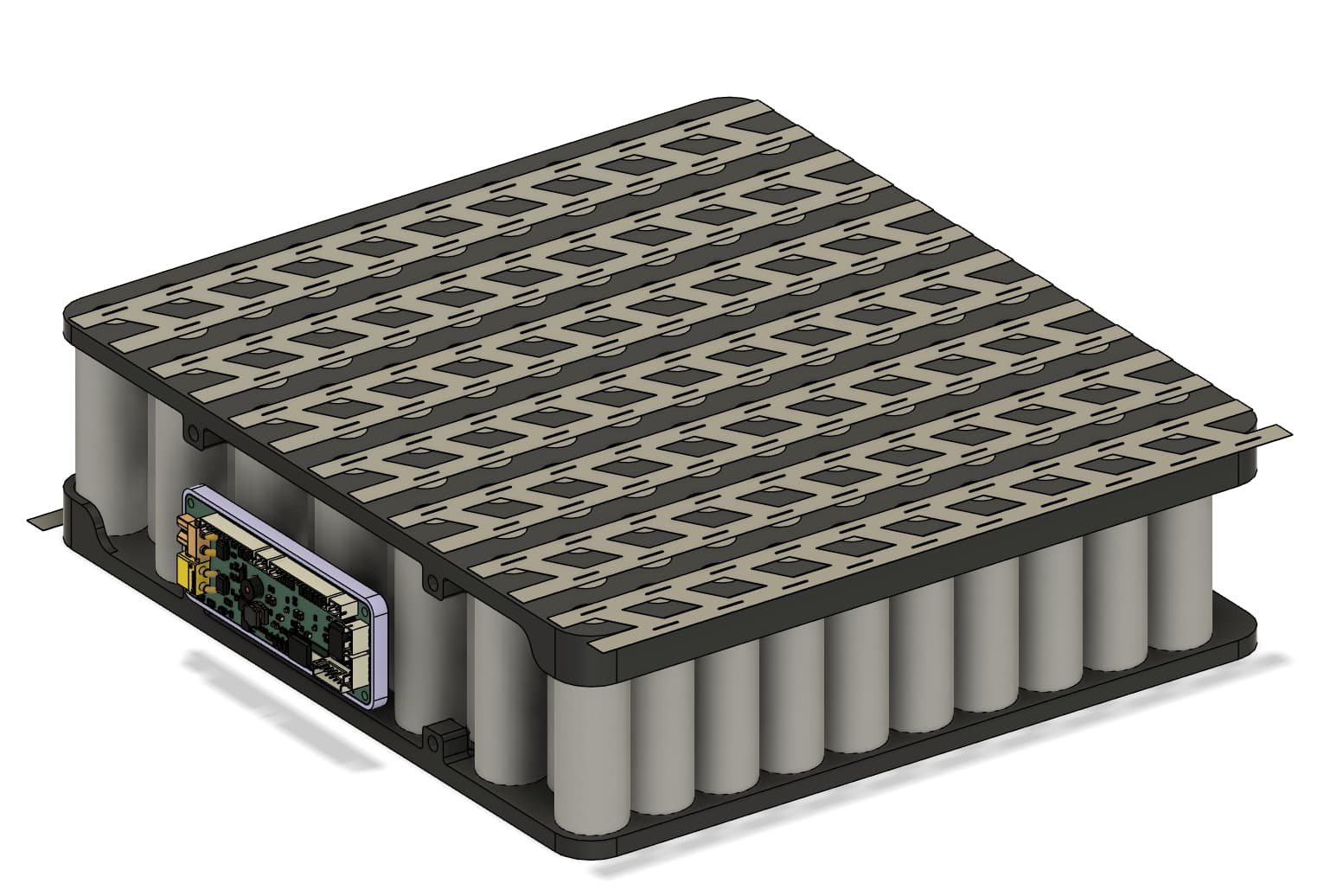
13s10p P42a with an Ennoid Xlite 4 BMS. Currently printing the cell holders for validation in PETG, but they will be ASA once I get the panels back on the big Voron printer. I’m still looking for an adequate charge-only port that will be water-tight when the plug is not connected. I couldn’t find any XLR-type inputs with an IP rating for submersion.
The BMS will be mounted on a separate adapter plate, which will provide some isolation from the pack and prevent rubbing, and give some cable guides for the balance wires.
I’m still working on the exterior, but I’m considering an acrylic top with a twist lock to secure the battery to the board, similar to a window latch.
Good idea to put the ennoid on a heat sink, this is required if you want to charge with currents above 10A. For a 10P pack, 15-20A would be good, otherwise it takes forever to charge the pack. Not sure about balancing with ennoid, as this BMS is mainly used in Onewheels where most packs are 2P. Balancing current of the Ennoid is only 50mA, so it will take some time to balance.
Hmm, I didn’t catch the 50mA balance current. I’ve designed the holder with a modular system so I could, in theory, swap out the unit, but I think I’ll give it a shot anyway since I have it in hand. It should be pretty readily apparent if the cells go out of sync. I’m also going to install some pico fuses on the balance lines as an extra layer of insurance, although with the routing, I shouldn’t have any crossed lines.
I’m planning on a 20 amp golf cart power supply to provide the juice, going with a lead acid version and hoping I can juice it up to 54.6v via the onboard pots and keep the trickle charge function to keep it alive when balancing as I’m not sure if the Ennoid does passive or active balancing. M20 connector will be the bulkhead penetrator for the charge port since the screw on cover is more confidence inspiring in my mind. 250 amp mega fuse on the positive out, and hopefully that covers the big failure modes.
I think balancing is only passive, if one cell is lower, it has to discharge the rest to the same level. Monitoring is nice, if you connect it to vesc over can, you can see cell info directly in vesc tool. You can also directly connect to it over BT.
For the fuse, if you want a smaller form factor, midiOto 200A works well for me and is smaller than a mega fuse. It‘s rated for 58V.
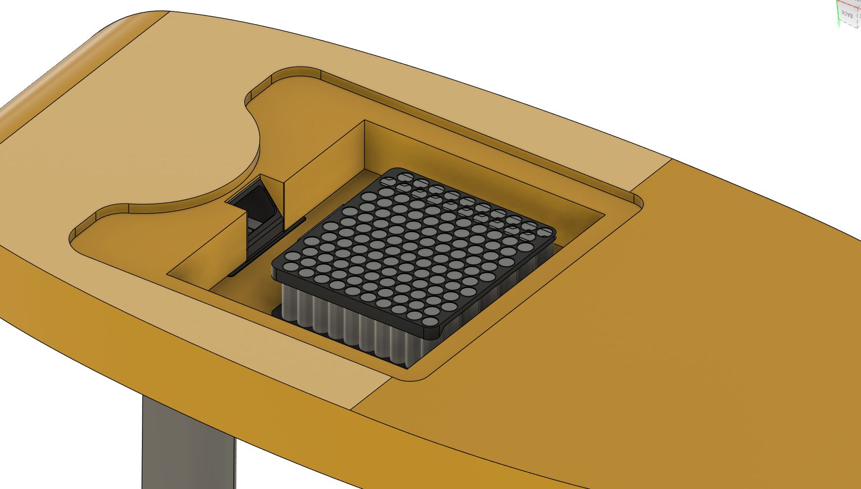
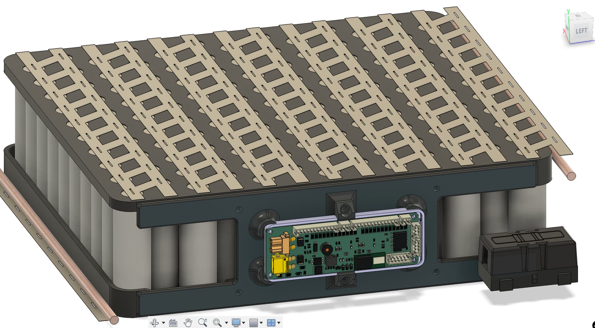
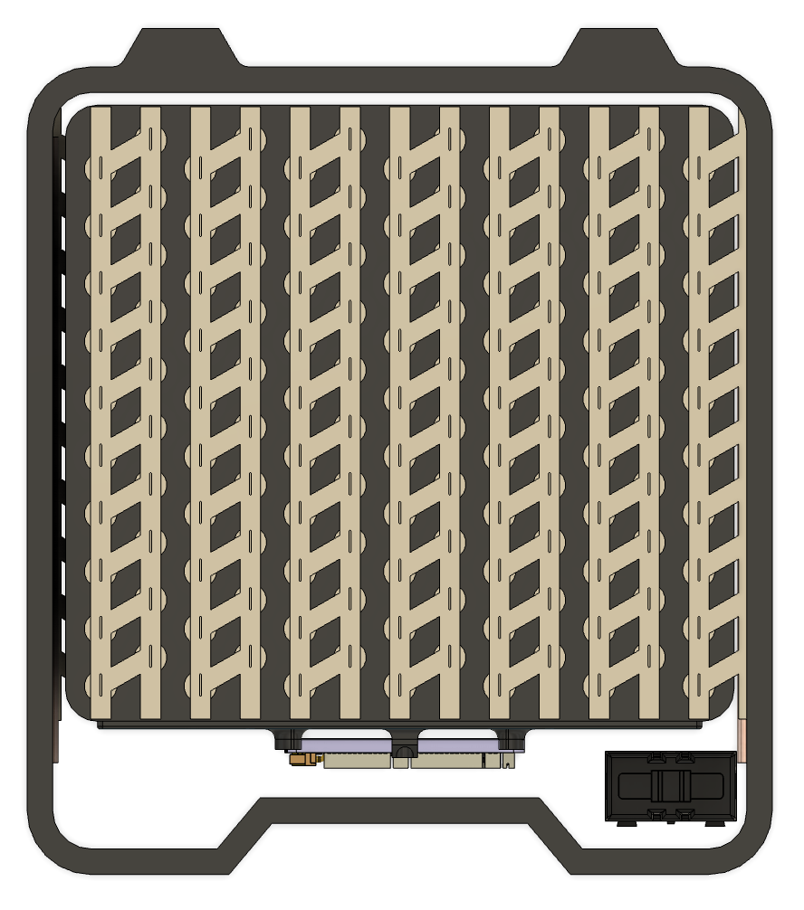
200A is tight on my other use case for a remote-operated rope tow, but its size is very convenient for integrating. I’m still trying to figure out where to place it, though. I want it as close to the positive rail from the battery as possible. I will be using it as a terminal block for the charge system too. The Ennoid in this photo will be flipped upside down so the c0 pin is on the left side instead of the right, as it is in this photo.
I also have to figure out where I will have the two 4AWG wires exit with the CAN bus cable, too, quickly running out of space for clearance. The final case design is still very much a work in progress, but I added a simple one as an example of space constraints.
So did some back-of-the-napkin math with the p42a yields a possible current of over 3k amps… mega fuses and midi fuses don’t have that level of amp interrupt capacity (they are typically in the 2kA range). Looking like I need to figure out how to fit a Class T in here, but I’m a little nervous about having a fast blow in there.
Edit: turns out a fast blow is relative, they pop at roughly the same rate for low currents of around 200% of their sticker value. The t-class, however, doesn’t have the thermal derating issue that the mega and midi fuses do. It does, however, pop much faster at high amp loads (dead shorts). Now the scope of the problem is a bit higher as I realize that 3000 amps is a single cell at 48V, and I have 10 of them in parallel. In a nutshell, while the fuse will blow, a mega or midi won’t break the circuit until something else vaporizes a wide enough track to break the arc, not at 30k potential amps.
OK, t-class fuse holder integrated into the outer case, less than ideal, so I’ll need to be careful when connecting it. I have some 4awg marine cable that I will attempt to use, but the bend radius on this is… less than ideal. I also went with a printed bottom case since I’m short on acrylic atm. Top plate will be acrylic and screwed down with a flat seal, I’m hoping to get away with 1/8" acrylic but deflection due to oring/seal pressure might mandate a different solution like just RTV sealing it up. Just fits in a 350mm Voron, so print is underway.
This is a nice looking case, reminds me of a fliteboard battery.
Also, 4awg cable sounds miserable! I don’t even know what connectors would work with such large wire. Are you sure you don’t want to just use 8awg? I think that’s a much more common and usable size for efoils. My 8 awg battery lines have never been hot, just a bit warm