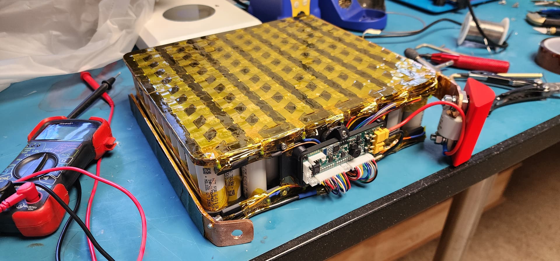
I have astrip of kapton on the back between the fold and the cells plus a syrup on kapton on the back of the busbar. I can put a strip of fishpaper on the side, i added liquid electrical tape benhind the screws mounts since they were a bit close to the cells at around 2mm. Should be fine but details matter for something that will live in my basement most of the time. I’m not going to put fishpaper on top as i want to keep the cells visable but i will add a few spacers to fill any gaps.
I built my first 3D printer back in the Darwin days of the RepRap project. ASA and ABS both develop some intense internal stress when printing long sections. A trick can be to introduce a series of sharpe bends in a part,. This turns out into a 3d printed spring. You can also print at a higher chamber temp, i try to keep it at 50c to 60c. PPScf also likes the hot temps for adufferent reason, laper bonding. You might also notice i didn’t print the ESC box in the normal orientation. it was printed with the cable entry flat on the bed to reduce the loop length and this the internal stresses. PPS CF isn’t compatible with my bigger printer currently so I’ve tried to keep everything within the build size of the X1C. The bigger problem with ppscf is it’s slightly conductive due to the carbon in it. The case is made from petg but it’s really like to swap it to ASA for thermal reasons.
It’s great that you have such an experience. Consider that I just shared my negative.
Before printing ABS and ASA, I always warm up the chamber, choosing the plastic drying mode. I also seal the door and window for throwing out poop with paper tape. But this did not help me much, unfortunately, except for the absence of warping of the model.
I wanted to clarify, are we talking about PPA-CF or PPS-CF?
PPA, my bad, I get the two mixed up due to their similarities. I have used PPA-CF as a static mitigation technique since it will bleed off static and higher voltage charges due to the CF reinforcements. It is pretty ok at blocking signals, too, which is a concern. You won’t notice this unless you test it with a megger or insulation test meter. I’ve left the professional side of things, and I am now an engineer teacher, so I explain a lot of things in greater detail than I might need to out of habit. Please don’t take offense, I have no idea who will read this in the future or what their experience will be.
For your print issue, cover the top glass and sides with a blanket if possible, leaving the back open so the electronics can vent. This applies to P1S or X1C models. It will also really help with any ASA/ABS cracking issues to go above 60 °C. Since the P1S doesn’t have a chamber temp sensor, you need to rely on the hotend thermistor. Don’t turn it on till it reaches 58 or higher, and you should get some very tough parts. Oh, and let the part cool down in the chamber without venting the chamber post-print; it’s on by default. Slow cooling is key. Annealing the post-print before removing the supports is also a good idea to reduce internal stresses. However, with PPA-CF, this approach becomes stiffer and more resistant to heat, but also much more brittle.
Everything is ok, I am not offended and grateful for the advice. I tried to print PPS-CF solely out of curiosity, since for my application it is inferior to PPA-CF in all parameters, excluding temperature resistance. To print at 330 degrees, I had to modify the X1C hotend with a resistor, but the stock heater only worked for 10 hours, after which the ceramic layer cracked.
By the way, I spent a lot of time annealing PPA-CF, because I print mostly blades and I need to make them as rigid as possible so that they don’t straighten out at high speeds and lose efficiency, and at the same time don’t break when opened abruptly. And here’s what I came to: I don’t anneal blades anymore )
That explains, PPS-CF has a way higher flexural modulus, meaning it’s much stiffer. Certainly seems like a better material for your use case. As for shock loading, elastomers are your friends. If you are making folding props, then take a look at polyurethane o-rings, around 90A durometer. They make outstanding shock buffers.
I may switch to this material in the future when I have a printer with a stable high temperature hotend. So far the blades I remove from the X1C bed work without problems. In any case, I will take your information into consideration.
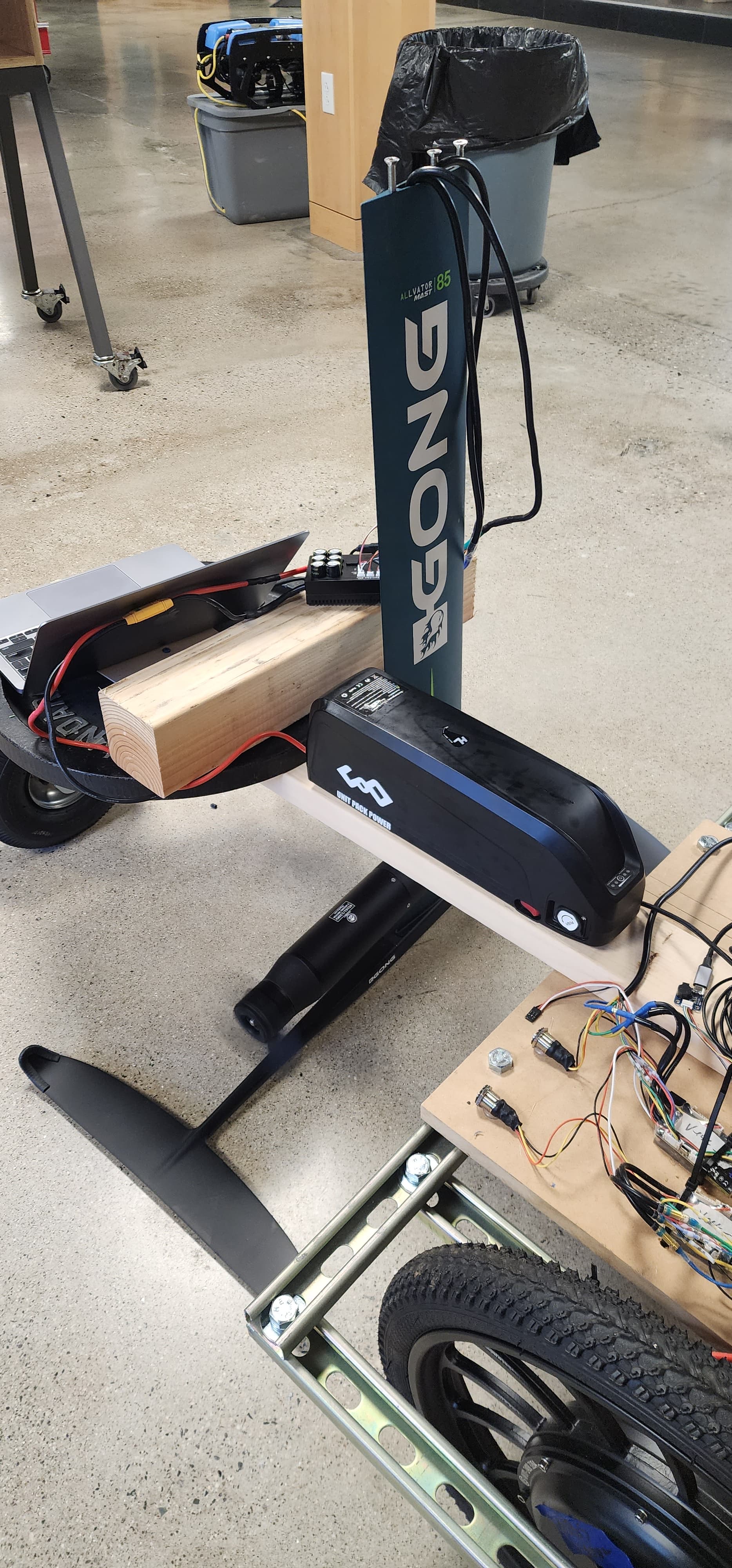
Got the BMS wired with fuses on the balancing leads. I should probably put a 20ish amp fuse on the charge leads, too, but I discovered bigger problems. My “golf cart charger” is outputting an AC voltage; luckily, I didn’t connect it. Looks like I’ll be needing to get a better system for charging. I’m all ears if anyone has a recommendation that is under 20 amps (ennoid max). In the meantime, I’m going to hotwire a charger from my classes’ e-bikes. Unfortunately, it’s only a 2 amp, so I should go get a coffee.
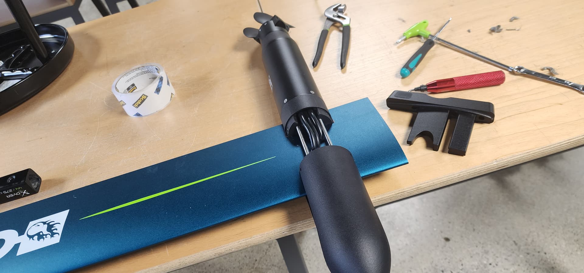
Got the wires in the mast but i noticed my motor doesn’t feel too smooth. Not sure if i damaged some wires though. When i was pushing them up the mast one of them aparently stretched the insulation of the wire out. Now in feeling a little bit like cogging on the motor. I’m not very familiar with these motors but it feels like a phase shorting but i can’t find anthropology physically or electrically. It just feels rough, are these motors normally free spinning?
Just wired up anothe 75200 that i could afford to lose. Seems to be working fine. Amp draw is low, heatup isn’t bad. Just feels a bit rougher than the outrunners in used to.
Thanks, I’m putting some 3m 5200 series sealant on this thing so a i don’t really want to have to take it apart… I ordered the blue stuff instead of the fast set red so I’m here waiting, again. Hoping to get the powerunit done this week and then start working on the board itself. Oh and i have some Ditchol AM Hyrdo on the way to make all of the prints waterproof.
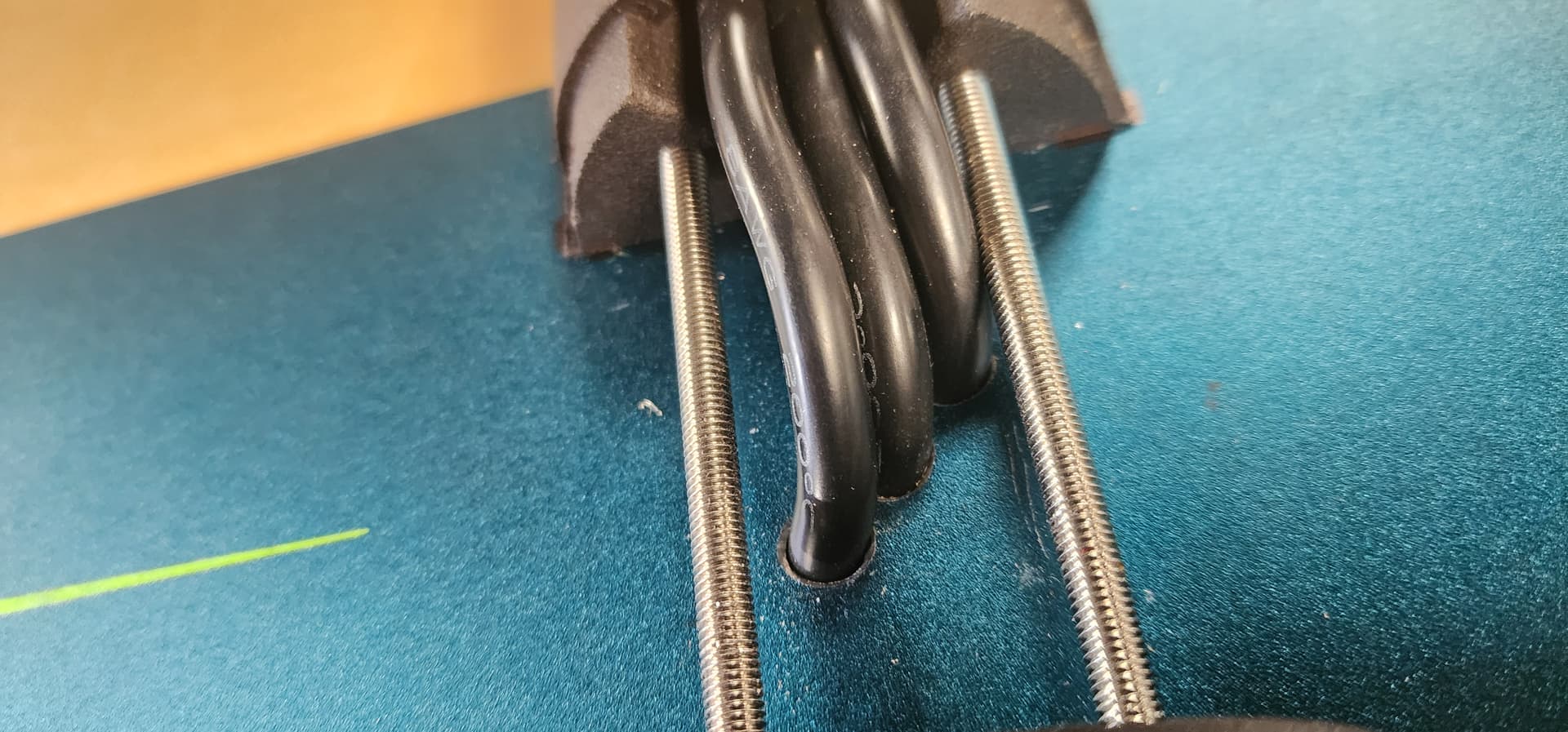
I do hope you deburred the holes for the cables. Would’ve personally gone for one large hole where all the cables go through but as long as it’s deburred from both inside and outside the cables should be fine, otherwise you might have an issue with cables getting cut open…and those cables will rot.
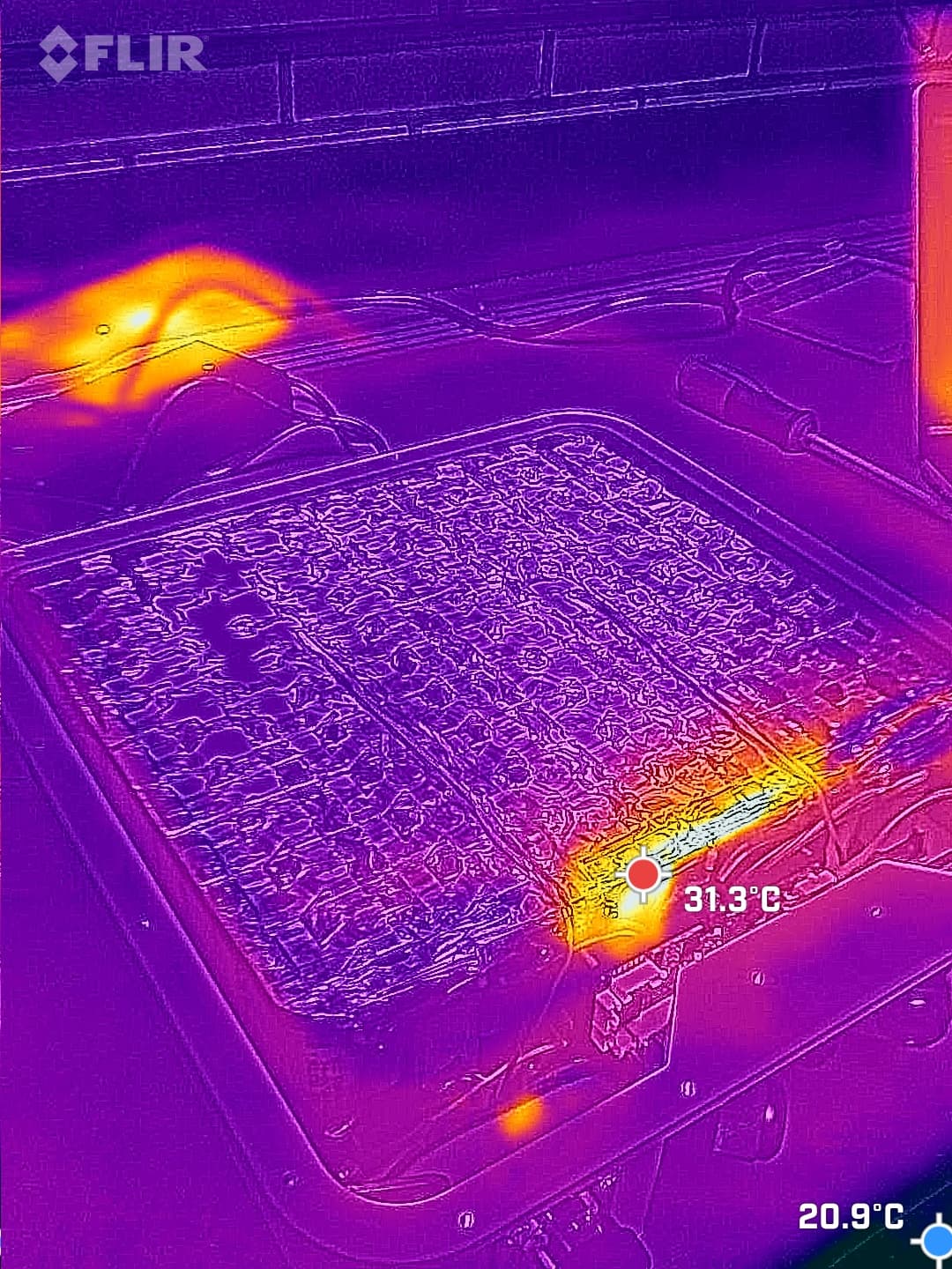
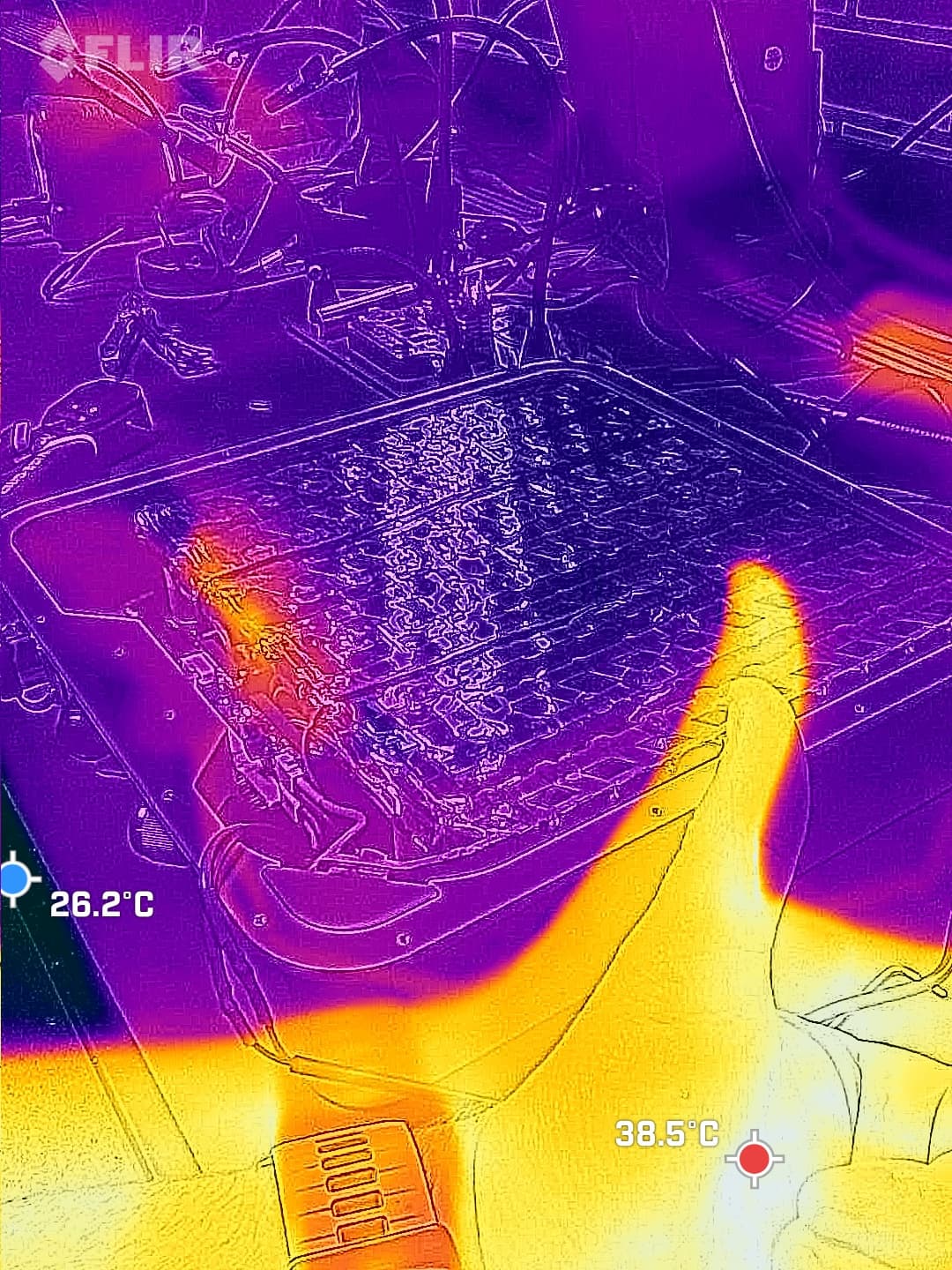
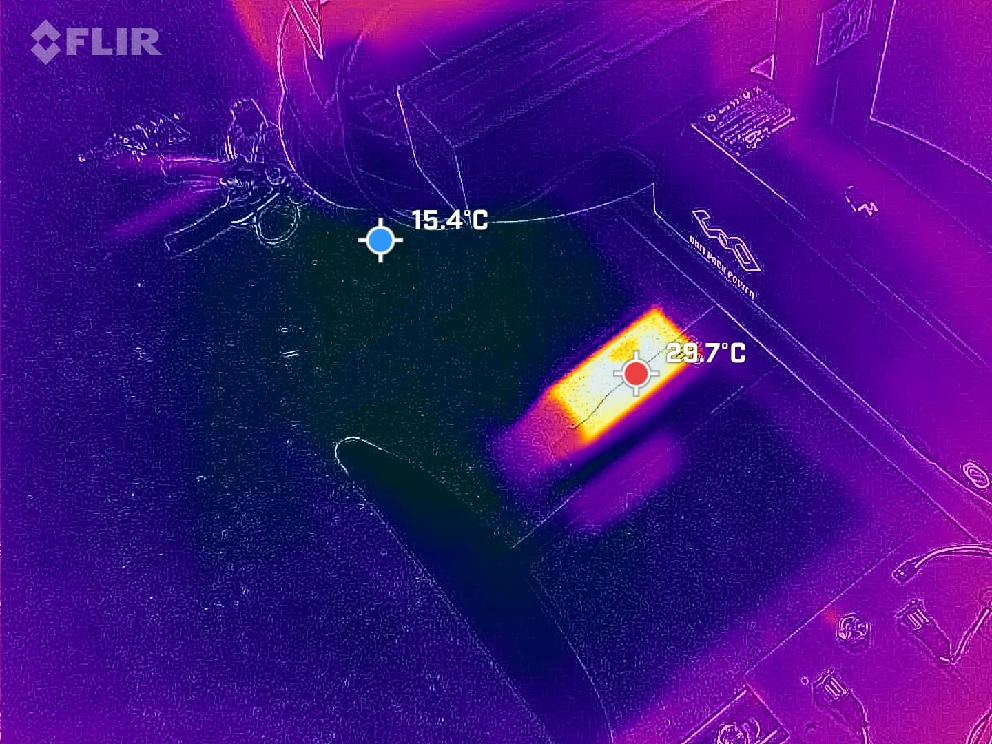
I deburred everything went with 3 holes mostly ti reduce the amount of sealent. In hindsight i would have just done one big one too. Good catch on the seal. I didn’t realize the seal could be damaged by running dry. I ran it for a minute or two while i checked with the thermal camera.
Do you plan to waterproof the mast? I am annoyed that there is water in my masts. I want to waterproof them, but I don’t know how yet - silicone will kill the wiring, I am too lazy to change the cables to others with Teflon insulation. For now I am thinking about split bushings made of TPU.
Yeah, I will waterproof the mast. The 3m 5200 is a permanent adhesive sealant and is urethane-based. I emphasize the permanent, too. It is designed for hull penetrations below the waterline in marine settings. Shouldn’t hurt the silicone, but also won’t really stick to it well without a lot of prep. I had to remove some of this from a boat years ago; I ended up cutting the cables as the urethane cables bonded to the adhesive and grinding the rest out. The 4200 is more removable and better for things you might want to remove in the future, but it is still able to handle below-the-waterline hull penetrations. Unfortunately, it doesn’t stick to silicone, so short of a proper compression fitting with a grommet, I hope it is enough. If not, I will just pull the plug and let the whole thing flood and, more importantly, drain.
If you plan to fill it with silicone and not touch it - it works. I constantly change motors, controllers and removing silicone usually ends up damaging the insulation.
Waiting on glue still, so I got some 25lbs XPS foam to try my hand at shaping. I’m not sure on the general construction yet, though I was thinking about making the bottom of the battery compartment out of a thin 10 mm-ish thick piece of foam with the battery locating features molded into it and a matching top hatch. I’m not really sure how many layers of carbon to use or what weight to choose. On snowboards and skis, I use 16, 19, or 22 oz triaxial glass, so that doesn’t really apply to this, so I’m winging it unless someone has a better idea.