hi everyone, its good to see a tailor made design in the works, brilliant*
has anybody ever tested one of these prop/duct assembly’s, i was thinking to test the 150mm model, and maybe try different props using the duct body, i don’t want to risk buying one if there no good for the job
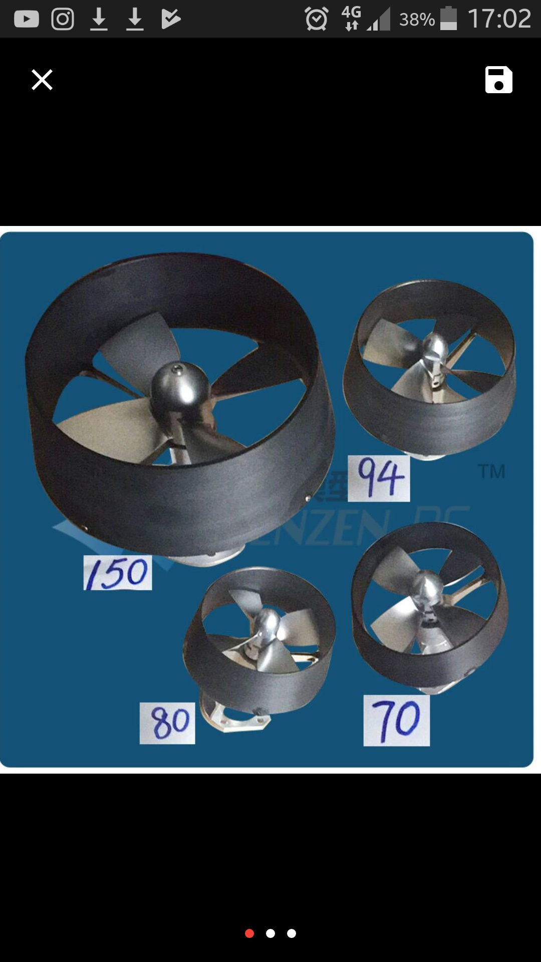
the duct on those propellers look like kort-nozzles. (low performance) you should go for rice speed nozzle (high performance nozzles with airfoil cross sections, not straight).
2 Likes
Actually with a efoil at max speed, a thin straight nozzle, purely designed for that would most likely be better. Both kort and rice nozzles are designed to give enhanced thrust at lower speeds. They do this by reducing tip losses. But eventually he shroud becomes drag at high speeds.
2 Likes
@Roboshack Could you please post the original answer of Martin Hepperle in German? I think there are a few native germans on the forum and they might profit from that.
4 Likes
@Dude No problem, here the original reply…
Im Wasser gibt es das Problem der Kavitation, das grob vergleichbar mit der Annäherung an die Schallgeschwindigkeit in der Luft ist.
Beides hat starke Auswirkungen auf die Profilumströmung und kann zu starkem Widerstand und Strömungsablösung führen.
In beiden Fällen sieht die Lösung ähnlich aus: die Profile bekommen eine große Dickenrücklage (z.B. 50-60% der Tiefe und müssen relativ dünn sein.
Unter Wasser hängt es von der Tauchtiefe ab, bei welchem (Unter-)Druck Kavitation auftritt - ein U-Boot hat es da leichter als ein Surfbrett.
Man muss versuchen, den gewünschten Auftrieb mit relativ wenig Unterdruck (-Cp) am Profilschnitt zu erzeugen, was bedeutet, dass die möglichen Auftriebsbeiwert begrenzt sind. Während man in der Luft problemlos Auftriebsbeiwert von 0.7 bis 1.5 für den Entwurf verwenden kann, muss man für Hydropropeller eher bei 0.2 bis 0.5 blieben.
Für eine genauere Untersuchung muss man sich die Cp Verteilung am Profil ansehen um dort festzustellen welche Cp-Werte örtlich (z.B. an der Profilnase) bei welchen Ca-Wert erreicht werden. Diese muss man dann mit dem “kritischen” Cp Wert vergleichen, der von der Tauchtiefe abhängt.
Siehe auch Hydroprops und Hydroprops .
Grob gesagt sollte also der Entwurf Profile mit großer Dickenrücklege und geringer Dicke haben und die Entwurfsauftriebsbeiwerte nicht zu groß sein.
Das sieht man auch schnell wenn man einen Schiffspropeller nachentwirft - er wird die relativ große Blattbreite des Originals nur erreichen, wenn man niedrige Auftriebsbeiwerte im Entwurf wählt.
Die Profile sollten nicht zu sehr gewölbt sein, die in JavaProp enthaltene MH-Reihe ist da nicht so gut, besser die Clark Y und E 193 Profile verwenden.
An der Nabe können diese dann im CAD noch aufgedickt werden um genügend Festigkeit zu bekommen. Da an der Nabe sowieso wenig Schub produziert wird, sollte diese nicht zu klein ausfallen (und den recht unwirksamen Bereich abdecken). Zur Blattspitze hin sollten die Profile eher so 5% oder dünner sein, da müsste man das Clark Y oder E 193 dann dünner machen. Dort würde auch das ARA D 6% Profil ganz gut passen.
Ansonsten würden Profile der NACA 64xxx und NACA 65xxx Reihen ganz gut passen, mit geringen Wölbungen von ca. 1%.
Im Internet findet man auch da ein oder andere Dokument zu Schiffsschrauben in dem man auch Profilformen erkennen kann.
Im klassischen Schiffsbau ist aber vieles sehr empirisch gemacht (z.B. die “Wageningen” Propeller), das ist nicht mehr unbedingt “State of the Art”.
Für JavaProp spielt die geometrische Profilform keine Rolle, es kommt nur auch die aerodynamische Charakteristik an (Nullauftriebsrichtung, Auftriebsbeiwert beim Entwurf). Die Geometrie taucht dann nur im Export wieder auf.
Man könnte die Profile auch hinterher im CAD Modell noch austauschen, sofern die Nullauftriebsrichtungen übereinstimmen. Die Auftriebsanstiege (Ca = f(alpha)) sind bei allem Profilen sehr ähnlich und praktisch unabhängig von der Profilwölbung. Der Widerstand (und damit der Wirkungsgrad) ist natürlich schon von der Profilform abhängig.
Der Export schreibt tatsächlich nur die Oberfläche, keinen Volumenkörper, da ja sowieso noch Anpassungen an der Nabe und an der Spitze vorgenommen werden müssen. Meistens ist es am besten die Profilschnitte zu einer neuen Oberfläche zu verbinden und vorher die Schnitt im Nabenbereich und an der Spitze zu modifizieren.
9 Likes
Uff, da bin ich Mal gespannt!
1 Like
Very interesting. Now can you explain that to us like we are 5 year olds 
1 Like
Well the easy part of this is to imagine you all as 5 year olds, the other part is really tricky. Very much propeller voodo in German, as I originally said. Takes some time to figure it out step by step, even if you are a German native speaker.
3 Likes
Well said… Makes sense now, Cheers! 
hj, i got a lower unit off a johnson 5hp outboard, planning to use the prop shaft and the seal plate piece, the prop is a little big 9.1/4" x 6.5 pitch, how did the. Solas Amita 3 Diameter 7 1/4" prop work out , thinking i might try that one on my ple60 5.1 gearbox with the sss360kv, would be great to hear how it worked out for you,
The problem with rim drive: patents patents patents.
Anyone thinking of putting that on a commercial efoil is in for a dozen Cease & Desist letters a week.
True. Have looked a little into it, found a few patents that are pretty old, so might be a small window to get around the remaining valid patents. Would be interesting to develop and build anyhow.
Actual energy potential contained in a cease and desist letter. Near zero, we have been told in the past to ignore them.
“Getting around” patents is a nice concept, but a patent holder has broad possibilities of threats, the only resolution of any conflict is legal action or mutual understanding. Even if it is seems glaringly apparent that there is no IP overlap. The slightest amount of overlap will open up a lawsuit.
A lawsuit, at the very end, after all the dust has settled, with a clear resolution of infringement, results in the court deciding on a penalty. The penalty is based on a value of the IP multiplied by the cost of the product being sold. With the possibility inthe US of triple multiple if deemed willful, countries like Japan, no triple multiple, just penalty.
The value of the IP is argued between the two parties before the court, based on what a reasonable licensing royalty. The patent holder says the value is 50%, the other party argues the values of the IP is a reasonable 2%. The court knows that a maximum licensing value for such IP might be 10%. The court settles on a value of 5%, for example. In the example of a rimless motor in a system, this value is based on the cost of the motor in the system. Total foil board cost sold by the “infringer” to his distributor $6000 retail value $10,000. Penalty is assessed on the price sold, not retail. Motor costs $400 * 5% = $20 * triple damage (worst case) = $60 * number of units sold. The other side will argue for legal fees, your side will argue against. Important here not to act wilfully, but to proceed through business actually looking to avoid infringing and act in the clear.
That, in the end, is the check that the patent holder gets for his hundreds of thousands spent.
Sucks to be a patent holder for a small idea.
The amount of cases that ever reach this stage is probably less than 1%, everyone realizes (exception Samsung v. Apple) that there is no benefit in continuing the legal fight past some point of financial pain.
Bottom line, make your good ideas, innovate, and don’t be intimidated. Incorporate. 
2 Likes
So be first with the innovation, have plan and means to execute, get ahead of pack, make sales while sun shines, while everyone else copies you.
2 Likes
Has anyone thought about using a mesh cowl rather than a duct?
I.e. a robust mesh for safety to prevent fingers and general mincing, but avoiding the limitations of ducting and also the lower maneuverability of solid duct when turning or rising/falling?
3 Likes
Hi Aaron
would you mind re-sharing the Dropbox link, it expired. I’m not commercially interested, I’m planning to build my own e-foil and still analyzing and evaluating different designs. 3d assemblies are a great way to understand how other people built something, before actually building it. Helps to avoid mistakes.
Daniel
1 Like
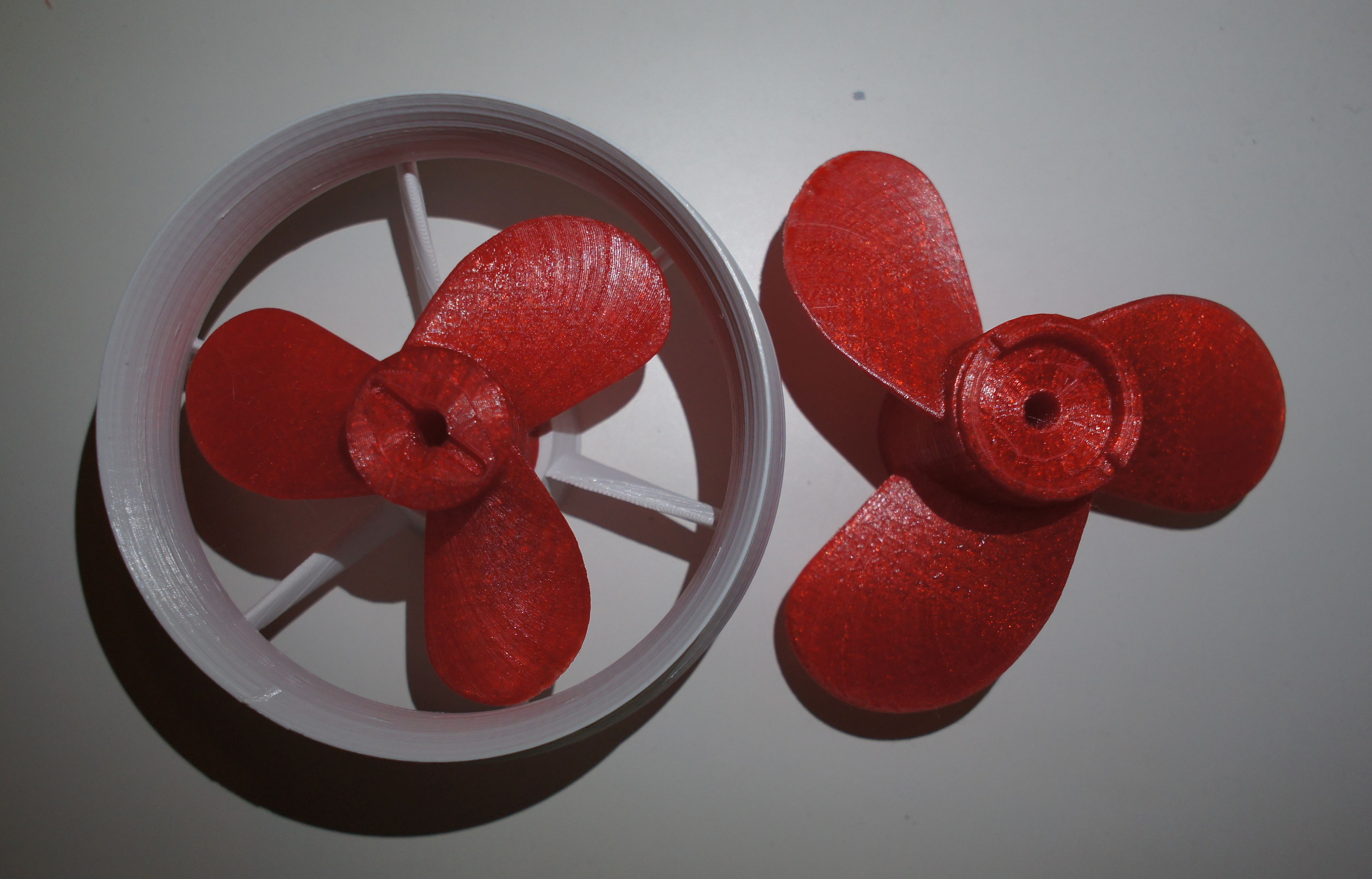
Looks like you got a nice prop! ![]()
I just thought it would be great to scale this one down so it can be used with @pacificmeister 's build so here it is Fusion Fusion
The second one is the same but I just kept the 9.6mm sided square hole
2 Likes
Oh I forgot, with this one the duct needs to be a bit longer but I couldn’t modify it because my solidworks version won’t open the duct file correctly
But maybe it’d be better to scale the duct up to @tunnelvision’s prop size
Hi Daniel,
Will do. What your email address? Do you use onshape?
Aaron
1 Like
Hi Aaron
Just been printing out your prop and other parts in pla for testing but will be getting some apolloX soon. Just wondering what bearings, seals etc you use with your setup and where to buy them? I’ll probably copy your board to mast connections too… Where did you get those?
Cheers!