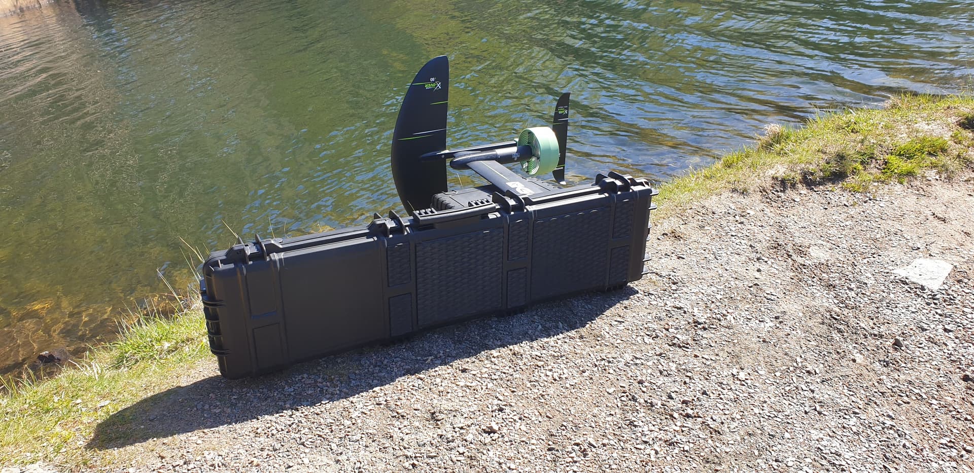
I’ve just finished building a sniper rifle case board based on the design by @superlefax and @kotnascher design in this thread: [Surf n' Destroy] Building a flying sniper rifle case
First of all I must say that I am very thankfull for all the information provided earlier. I made some modifications to customize the design, that I would like to share.
Basic info:
Board: Nuprol X-Large Hard Case Waffenkoffer
ESC: FSESC7200
Motor: Flipsky 65161
Remote: Flipsky VX3
Mast and foil: Gong Allvator V2 X-over
Batteries: Powerworks 60V6AH
My modifications:
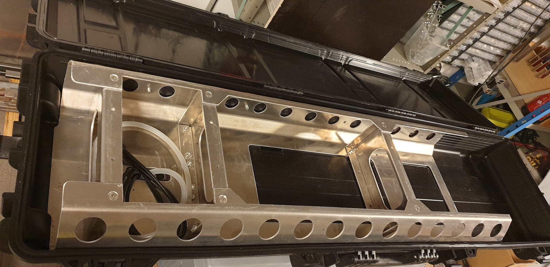
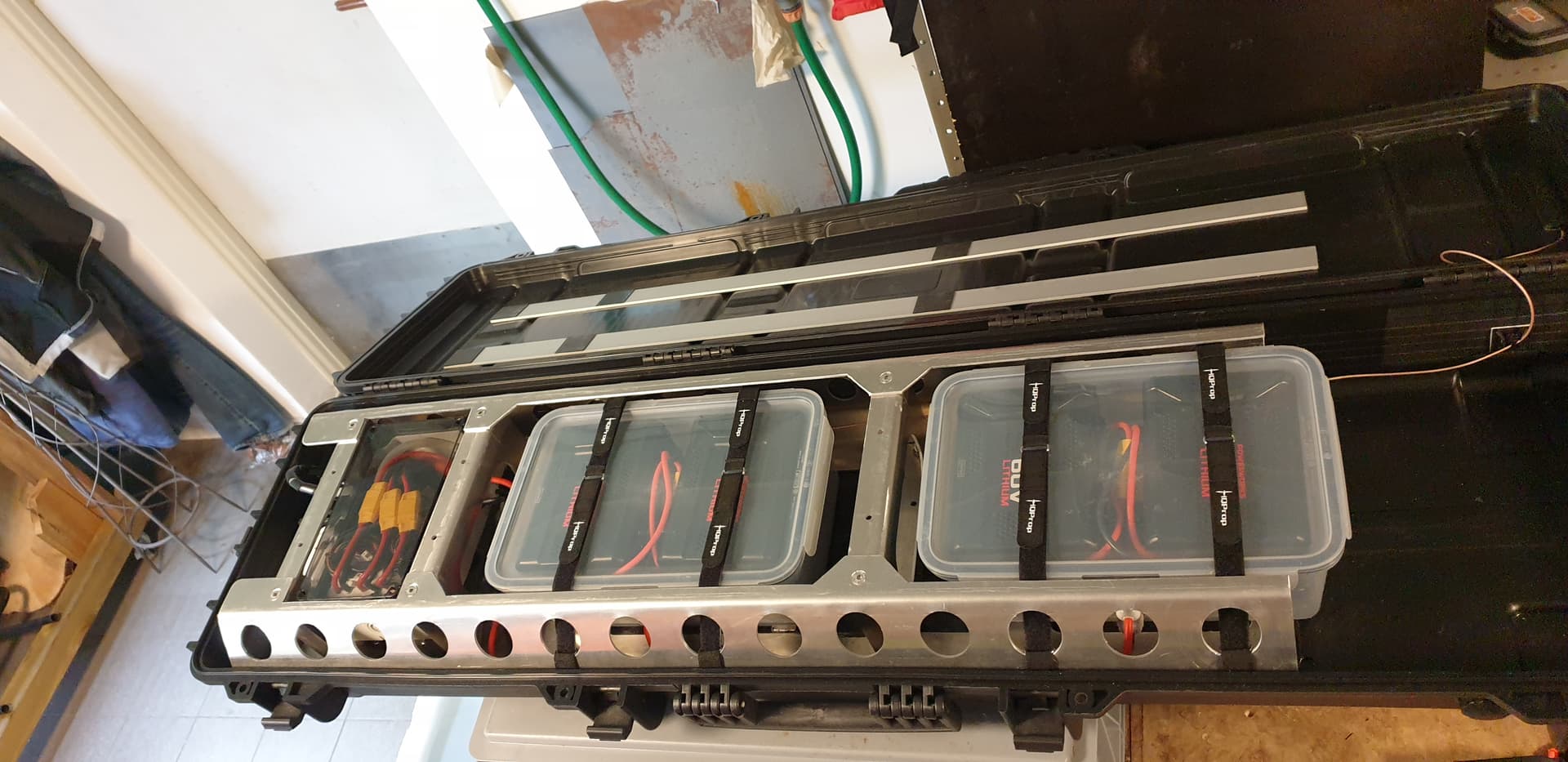
Extended the 3 mm aluminum framwork to also support the lid and added lasercut reinforcement brackets to simplify the build. This was all manufactured by the company Laserboost in Spain to a very reasonable cost. You just send in 3D solid STEP files and back comes cut + bent parts. They ship to Sweden. https://www.laserboost.com/
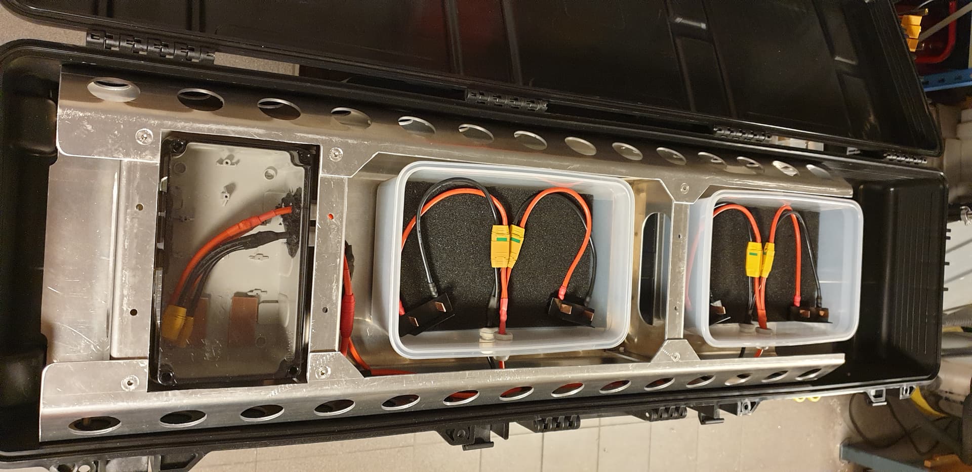
Used 4 standard Powerworks 60V6AH tool batteries from Bauhaus with custom 3D-printed connectors placed in waterproof IKEA food boxes. I opened one of these batteries and there are 15S2P quality Sony Murata VTC6 cells inside. https://www.bauhaus.se/batteri-powerworks-p60b6-60v-6ah
Unfortunately it seems Bauhaus are removing this battery from their shelves now.
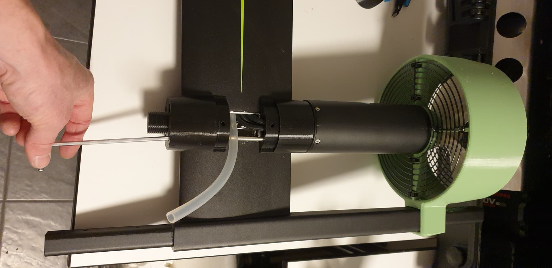
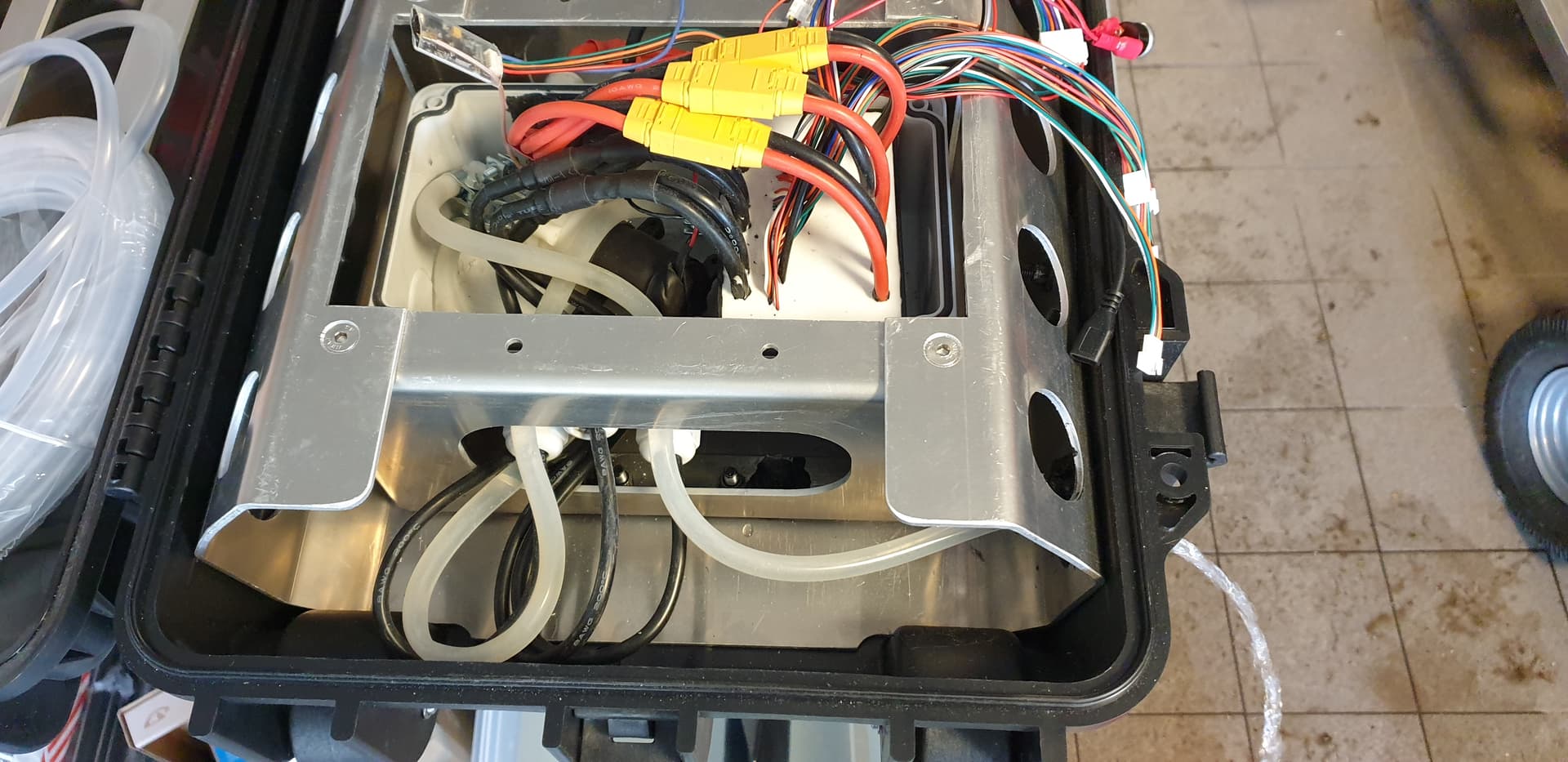
Added water cooling with modifyed nose cone and this self priming pump: 12V 180L / H vattenpump med fäste - Opencircuit
That pump had just the right suction power to bring water up through the mast and through the Flipsky heatsink by itself, with a decent flow. Still fitting inside the control box.
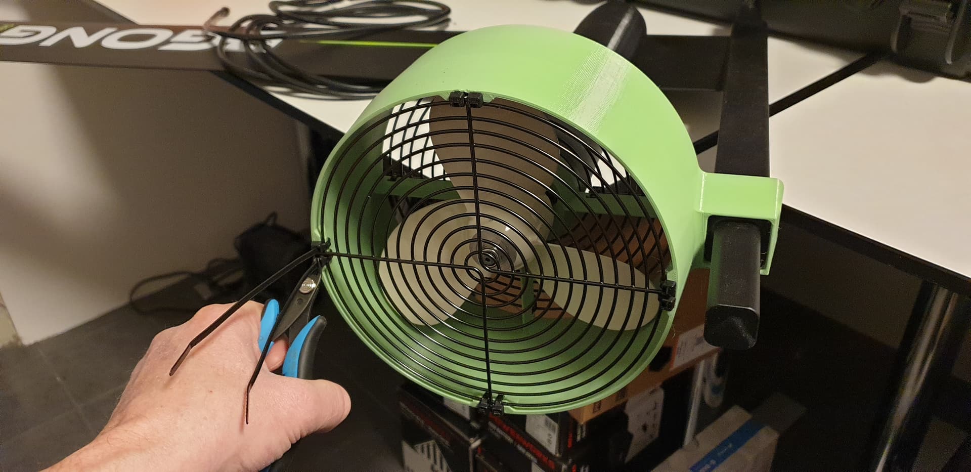
Added custom propeller duct with 180 mm computer fan grill as additional foot protection.
I had some doubts on the first testride that this board would be hard to get flying, but by setting the VESC to max current 200A and abs max current to 300A it just pops out of the water like a dolphin with full throttle. My weight is 75 kg.
When using tool batteries its extremely important to charge them full, then check all voltages and finally check that current is not higher than charging spec when they are connected together. These had an offset of 1V and that only created a current of 1.3A, so that was perfectly fine.
Lids and straps mounted on boxes. Here you can also see 3 x 40 mm aluminium bars mounted with double sided tape to top of case. It felt a little bit soft. Antenna wire to top is visible as well.
The battery packs have a built in sheet metal fuse without any marking, so I could not know the rating. But the VTC6 cell spec is 20A without temperature monitoring and 30A with 80 degrees cutoff. So I figured that I could draw 40A per pack (in 15S2P config) and thus 160A total from 4 packs. I set the VESC to maximum battery power 120A and everything worked fine. No fuses are burnt.
This pack does not have MOSFETs controlling the output, so the BMS cannot turn off discharge. It has 2 MOSFETs controlling input, to regulate charge only. This is a quite common practice in tool batteries, where the BMS would only recommend (through a com wire) to the tool to turn off the power. So in practice this is same as using a LiPO pack, where the VESC has to take the decision to stop, or lower the power draw.
The current is caused by all internal resistance in the circuit, generated by resistance spread out evenly over the 15S2P cells in the one package receiving current, 15S2P cells in the other 2 packages that are providing current and the interconnections. So the individuall cell resistance wouldnt be that high. Doesnt that sound right? (bonus points for the reader who calculates the internal resistance based on these numbers)
If the measurement is correct then yes it would seem correct - but still huge. This would mean you have higher losses in the battery circuit than in the motor, losses that would heat and damage the batteries with time. It would be good to find the root cause.
The cells have 8 - 18 mOhm internal impedance according to the datasheet, so 15S2P gives 158/2= 60 mOhm best case and 1518/2=135 mOhm worst case for one pack. This sounds high but I guess this is what you get when using 18650 cells. I have 4 of these packs in parallel so I would have between 15 mOhm and 34 mOhm out, if calculated correctly.
Yes, and this is the issue, if two parallel strings are 770mohm then 4 are 385mohm since there are 2x2 in parallel - something is off.
Either measurements or battery connection resistances are too high.
If it’s the measurement then you might have a larger current when connecting the parallels in reality (which is what i would expect with 1V diff)
Nice project ! 250usd/eur here for this metalwork, @kotnascher how much was yours ?
To both of you, how do you prevent water ingress at mast plate level ?
My tip would be to check the voltage drop in vesc tool or with a multimeter while using full throttle. If this battery resistance is real then it will show. Otherwise it’s just measurement error.
Our laser-cutted plate was 53€ from a local laser shop + 26€ for the other aluminiumprofiles.
We covered the whole suface of the mastplate with 5mm foam rubber to prevent water ingress
First I sealed the cabling in the top of the foil mast with marine sealant. I also sealed between the aluminum framework and the inside of the plastic box (kind of irreversible, which is not perfect). Then I used a flexible silicone gasket (that can be removed) between the mast plate and the plastic box.
Ahh, that is 770 mOhm in your calculation. I first read 77 mOhm and thought that is not a problem. Now I understand why you think it is rather high.
Actually, you are probably right that I took the photo of 1.3 A a while after connecting the battery and the initial current was higher. Good that you spotted this error. I will measure again when the voltages are off and come back with better values.
It is the standard propeller from Flipsky that I purchased in July last year. I believe they called it 173 mm, which I measured to need a circular tube with approx 184 mm inner dia. I am very sure that my propeller is not larger than 188 mm, as that is my duct / foot protection inner diameter.
Now Flipsky ship motors with a propeller that is called 190mm/7.5". Either they have increased the size of the propeller or they have renamed it. Perhaps someone else knows if they have changed this size.
After some further testing I have realized that the 180 mm computer fan grills are not so good. They lower the efficiency quite a lot. I highly recommend to not mount those.