Just came across an ad for Stoke foiling. Looks interesting as they’ve integrated the battery as part of the motor pod. I guess this is okay as it is mounted high up the mast.
Their motor pod is also a universal fit (rubber packers though) and a new remote design.
Priced similar to Foil Drive. Will be interested to see the feedback from people. I see a lot of feedback from people that think the Foil Drive product feels very “DIY”.
So what prevents people from implementing e-foil assist using this way of inlining everything on the mast ?
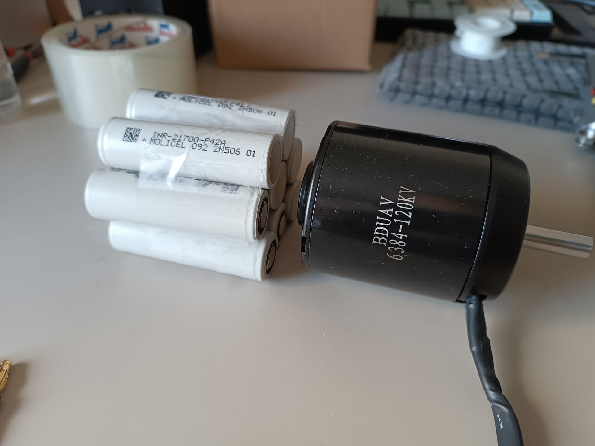
Weight of the battery is like P42a 70gr 16WH *10 = 160WH 700gr.
Need an effort 3d printing this. But it is feasible, right?
Lets open a thread about it and discuss it!
You are saying that it is easier to control the board when more weight is at your feet.
Probably you are talking from experience… I have not ride Foil yet.
I have a few questions though:
Isn’t it it is the lower weight the better - like a battery in a car?
Aren’t you controling the board by moving your center of bodymass?
Does it really make an impact, when 1kg of weight is moved 25cm lower ? (if it would, they probably would not make the product)
I think this is a very poor design for the Foil Assistant, a device that operates at the limit of its capabilities. When the board plunges into the water, this huge torpedo offers strong resistance. And I would really not like to have a battery that is constantly in water, in a case printed on a 3D printer.
Well who says its 3d printed? On the photos it looks like solid frame and tube… And I think they just did it high quality, at least it looks like and very similar to the #scubajet oder waydoo subnado dive scooter, which both work well down to 60m underwater…
just discovered this thread… am contemplating this design myself… @jezza, I agree with @lishine , my experience winging has left me with the opinion; the less weight in/on the board the better (which is why I want this assist for a prone/small board) - definitely better lower, certainly on foil but maybe less so (probably inconsequential) while taxi’ing (off foil). In fact the swing weight is largely what put me off winging.
My main concern with this design is more the impact it has to withstand when coming off foil - quite a bit of leverage… so for DIY I would probably lean towards aluminium tube with 3D printed ends/fairing.
I suspect this design is a lot more hydrodynamic than the Foil Drive gen 2 (or Manta as per this post ) - as you need to displace that (front facing) profile of the motor regardless… so extending that shape forwards shouldn’t add nearly as much drag as a whole new object under the board.
As mentioned this gives great benefit to cooling and no external wiring.
WRT waterproofing challenges. You would pot the batteries inside (or at least the ends of the tube (epoxy or marine sealant) so it’s 100% sealed with only the connectors exposed. Likewise the ESC. Just not sure about heat dissipation while charging - maybe thermal epoxy and a fan on it while charging (maybe a vent screw too)… and do so outside (I know a guy who nearly burnt his house down charging li-ion cells)!
Any idea what voltage the battery is and what KV the motor is?
WRT small battery capacity - prob not such an issue once you get good and need it less. But learning will chew threw a few packs. But I like that you could probably charge these small packs. And major plus is lower weight.
Put 3x8=24 batteries diameter=75mm, length =21cm in a cylindrical tube which is readily available.
The controller fits next to the mast.
Front cover 3d printable.
For charging switch batteries - either open the front and slide the battery like with FDgen2 or disconnect the box , like in Stoke foiling or in Flying Rodeo.
Potting the battery, controller and receiver - it is not hard.
The challenges to solve:
Detachable waterproof front cover.
How to hold the tube on the mast.
Yep. Although, space-wise 7 batteries fit perfectly (6 round with 1 in centre) together with a width of exactly 63mm (3x21) - and you can get aluminium tube of 70mmOD (1.65mm walls).
With this optimal (space wise) config you can only get 14 cells with 2 long and 21 cells with 3 long. which explains StokeFoil’s small battery (211Wh).
I think the best would be 10s1p (or 12 or 14s1p) for 2 long or 10s2p for 3 long (7,7,6). Which I would be happy with… just trying to decide on that or the FD#2 style under the board - 10s2p (stacking cells next to each other) would be 420mm long (plus battery zinc, wiring , ESC, etc).
Yeah 8s would be ideal stacking 1p per layer - but you need the next size tube. The 70mm tube fits, coincidentally, nicely over the 63mm diameter mast clamp I’ve printed (the motor is 63mm also)- which helps solve how to attach it.
The ESC could be thermal-glued onto the tubing next to the mast (easy heat sink) - same with Rx on the other side of the mast.
Exactly, yes. 10s2p is nice enough.
Although the problems of battery exchange and holding on the mast has to be solved. The attachment to the mast has to be robust, maybe the tube to be attached to the motor.
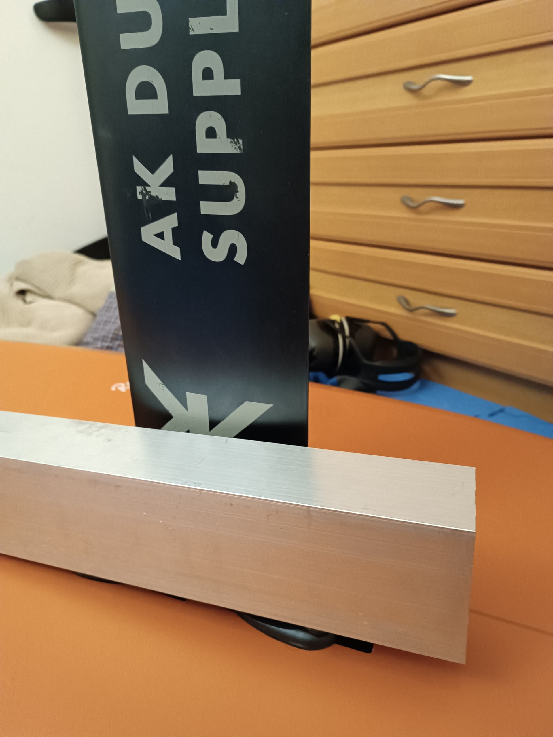
Are you considering here the aluminium box between the mast and board?
I thought about it. You can use 120x36x3 for one row of cells or 120x50x4 for two rows of cells. Maybe need strong spacers on the screws.
I moved from the fdgen2 concept to placement of 80x50x2 next to the mast.
That aluminum box may be even sealed one time including the esc and even the receiver. Exchangeable as a whole unit.
End of 2022 / early 2023, one year before the FDGen2, a member proposed a claw system to fix a motor to the mast. Does anybody remember who it was ? @brycej ?
@lishine yes (box between board and mast base plate) - yeah would need something solid under the screws -a lot of pressure - prob solid aluminium.
Re the SF torpedo/tube style - I was thinking similar - the battery section would extend over the mast - or at least maybe 1/3. Then have similar tube or 3d printed on the rear that would house the ESC and have motor attatched - and again extend forward across the mast.
Connecting front and rear…
on front/battery section have aluminium plate welded or riveted on that is perpendicular - ie like an end cap but inside. This would be at the very front of the mast (whether the tube ends here or exends with cutouts around the mast). This end cap would have holes for cam lock pins (the ones that pull the pin up when you push the leaver - like for adjusting a bike seat) - this with a rubber seal would hold it super tight.
have a 3d printed thread that fits inside the tube (fixed with either epoxy or screws from the outside). It could be one of those very course threads that needs to be pushed hard (against a rubber seal)then clicks into place. This is prob similar to what SF actually used (my guess).
Does anyone know if you can completely pot the ESC and receiver? that would make things easier (rear part of tube not 100% water proof)?
I haven’t done that , maybe somebody will talk from experience. But talking as an EE, rest assured you can pot ESC and receiver, I consider it as solvable.
The material is potting silicon, you look it on Ali or Digikey etc. It is thermally conductive but electronically isolate . There is hard and there is soft. For the ESC will be some specific work , for transistors may use thermally conductive epoxy, need to check if the back side of transistors connect electronically.
I don’t understand the cam lock in this case, that is strong, will not open and where is it placed.
You are probably good in mechanics. For me it is not simple enough to tackle.
The 1kg motor and printed pod is working , so why not put 1.5kg on the other side, ok.
How you would detach the battery?
Have you considered putting it on the body? People consider it as the lightest form of assist , aside buggy.