How does that fit into the real world?
Thrust at 30 km/h is equal to drag, a constant depending on your setup (board/foil/weight/water).
It can not really change depending on prop.
How does that fit into the real world?
Thrust at 30 km/h is equal to drag, a constant depending on your setup (board/foil/weight/water).
It can not really change depending on prop.
Is the onshape blade generator a public feature?
Will you allow for “Airfoil” change as a parameter?
I was looking into this earlier, and it seems like Naca 16 (15% mrophing into 5% at the tip… ) and 66 series are better suited for our use case… With up to 20% efficiency gains (according to AI… I didn’t run the CFD numbers… )
Which Airfoil did you use?
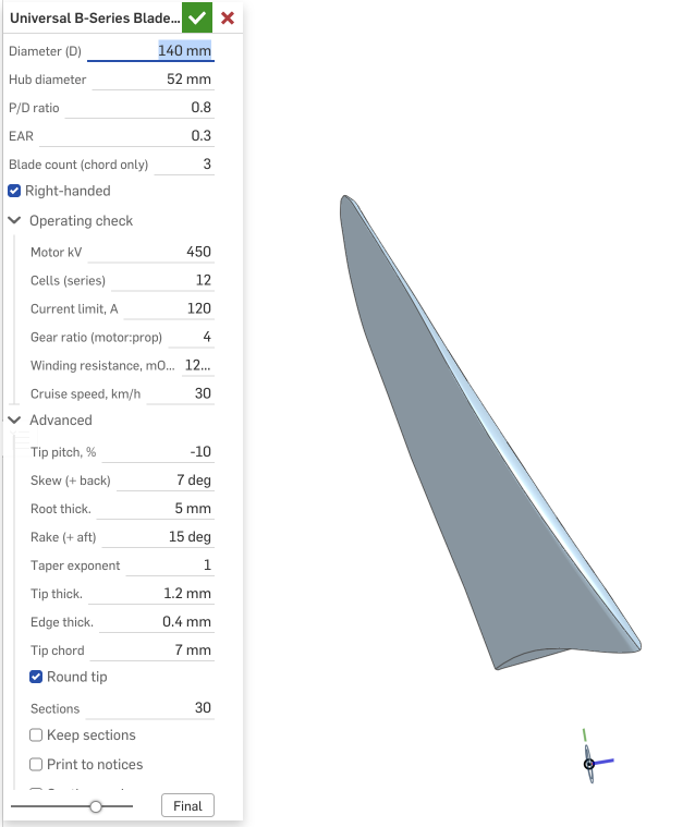
Yes, the FeatureScript is publicly available in Onshape — search for “B-Series Propeller Blade Generator” and have a go yourself.
Fill in the Operating check group (motor kV, cells, current limit, gear ratio, winding resistance) and it prints the predicted operating characteristics to the FeatureScript notices panel, updating every time you change an input. Leave the kV at zero and it skips the calculation entirely.
The 30 km/h figure is just a reference point to measure against (also a parameter in the script). If your drag at that speed is less than the thrust shown, you’ll accelerate through it; if it’s more, you may never get there. It’s not really a top-speed calculator — it’s there to give you a consistent point of comparison between designs.
It’s not currently using a published aerofoil section — it’s generating the shape from the Wageningen B-series tabulated section ordinates. They’re cambered inboard and flat-faced from about 0.7R out.
Foil Drive have quietly turned props into a tuning choice rather than a fixed part. They sell three, colour-coded, and MACkite did a video walking through when you’d pick each. Worth a look if you haven’t seen it — it’s the closest thing to a public comparison of blade geometry on these systems.
The short version: black is the standard one that ships in every kit, the blue is aimed at low-end thrust and take-off, and the grey at top-end speed and grip when you’re moving.
What caught my attention is what they actually changed between them. The blue (LR6) is 6% longer and 6% wider than the black, so diameter and blade area both move. The grey (MHR10) is 10% wider at the same diameter — area only, no extra length.
That grey one is the interesting case for what I’ve been doing in this thread, because changing area at a fixed diameter is exactly the knob I’ve been turning. Ryan describes it as the high-gear prop, and notes it aerates more readily when the pod surfaces. Which matches the numbers: more area at the same diameter means lower rpm for the same load, but more blade to ventilate when it breaches.
No actual figures are given — pick a colour for your conditions — which is fair enough for a product, though I’d love to know their real diameters, pitches and EARs.
Their system is nominally 40 V and rated around 27.5 kg of thrust on the three-blade alloy props, so a very different power envelope to what I’m running (12S through a 4:1 box, about 3 kW at the shaft). Not directly comparable, but the blade-area trades should hold either way. I think they’re on a 63-series motor around 120 kV, but that’s a guess — they don’t publish it
Yes — added it as a parameter. The list is now:
There’s also a camber input, as a percentage of chord, for the profiles that take one. The B-series carries its own camber and ignores it.
Two things worth separating out from your question. The “15% morphing into 5% at the tip” part is thickness ratio, not section shape, and that was already parametric — root thickness, tip thickness and a taper exponent. On a 150 mm blade, 7 mm at the root over about 45 mm of chord is roughly 15%, so the script was already doing that bit.
On the 20% efficiency claim, I’d treat that with some caution. Between well-designed sections at this scale I’d expect a few percent, not twenty. Where the section really earns its keep is cavitation and ventilation onset, not efficiency — in water the limit is how deep the suction peak on the back of the blade goes, which is a different problem to the lift-to-drag ratio an aerofoil is usually judged on. That’s also why I’d be wary of the high-lift low-Reynolds sections: they get their lift from exactly the suction peak you can’t afford near the surface.
Also worth flagging that the NACA 66 option is approximate. The 16-series is genuinely the four-digit-modified construction so that one is exact, but the 66 is defined by tabulated ordinates from potential-flow design, and what I’ve built matches its crest position at 0.45c rather than transcribing the published numbers. And the 66’s laminar-flow advantage largely evaporates on a printed surface, since layer lines trip the boundary layer near the nose anyway.
One limitation: the operating check only describes the B-series. KT and KQ are fitted to B-series geometry, so pick another profile and the numbers are for the equivalent B-series blade, not the one on screen. The script prints a warning saying so. Modelling section choice properly needs blade element theory with lift and drag data per section, which is a different tool.
Was just trying to understand what those numbers actually reference.
30km/h should be foiling speed for pretty much all setups. So drag is probably on the lower end for that setup.
I assume in your examples, the 0.8 can have high thrust at lower speeds?
So to get a real feedback, you probably need to consider the complete speed range.
For example your 1.0 version could possibly struggle to get the needed thrust at 20km/h and that way not even reach 30km/h?
Or do I interpret those numbers incorrectly?
Fair question. One speed on its own doesn’t tell you much. Here’s the same three props across the range — 140 mm, EAR 0.3, 120 A, 12S.
Thrust, kgf:
| P/D | 0 | 10 | 15 | 20 | 25 | 30 | 35 km/h |
|---|---|---|---|---|---|---|---|
| 0.8 | 58.6 | 55.5 | 52.1 | 42.5 | 32.1 | 20.9 | 9.0 |
| 0.9 | 53.2 | 50.7 | 48.6 | 46.3 | 41.3 | 30.6 | 19.3 |
| 1.0 | 48.4 | 46.3 | 44.5 | 42.5 | 40.5 | 38.5 | 28.8 |
Motor current, A:
| P/D | 0 | 10 | 15 | 20 | 25 | 30 | 35 km/h |
|---|---|---|---|---|---|---|---|
| 0.8 | 120 | 120 | 118 | 103 | 86 | 65 | 41 |
| 0.9 | 120 | 120 | 120 | 120 | 114 | 93 | 68 |
| 1.0 | 120 | 120 | 120 | 120 | 120 | 120 | 99 |
And for reference, thrust again for the same props, with the current limit taken off entirely — motor and pack only held back by voltage:
| P/D | 0 | 10 | 15 | 20 | 25 | 30 | 35 km/h |
|---|---|---|---|---|---|---|---|
| 0.8 | 74.4 | 60.7 | 52.1 | 42.5 | 32.1 | 20.9 | 9.0 |
| 0.9 | 81.1 | 68.4 | 60.3 | 51.2 | 41.3 | 30.6 | 19.3 |
| 1.0 | 86.9 | 75.2 | 67.7 | 59.1 | 49.8 | 39.6 | 28.8 |
That one’s theoretical — it’d want 215 A off the line on the 1.0 and no ESC I’d fit is doing that. But it shows what the limit is costing and where. Above 25 km/h the three lines are identical to the 120 A table, because up there voltage is the limit and the current setting is irrelevant. Everything the ESC limit costs you is below 25.
Half your guess holds up. The 0.8 does make the most thrust down low. But the 1.0 isn’t struggling at 20 — they’re within 6 kgf there, and past 25 the 1.0 is ahead. It’s the 0.8 that runs out.
Look at the current to see why. As the prop approaches no-load rpm there’s no voltage headroom left over the back-EMF, so the motor can’t push current through any more. At 30 km/h the 0.8 is only drawing 65 A of the 120 it’s allowed.
And yes, thrust equals drag in steady state, you were right about that. The tables are what each prop can make at that speed, not what it will be making. The surplus is what accelerates you, and it’s zero once you’ve settled.
Which brings up the bigger gap: none of this knows anything about drag. It’s purely the motor and the prop — what the drivetrain can put into the water at a given speed. Your board, foil, weight and how you’re riding set the other half, and that’s the half that decides whether you reach 30 km/h or more. Take these curves, draw your own drag curve over the top, and where they cross is your top speed. Where the gap between them is widest is where you accelerate hardest.
So I can’t tell you whether the 1.0 gets you to 30 — that depends on your drag at 20 and 25, not on the prop alone. What I can say is that the 1.0 has more left at those speeds than the 0.8 does. If anyone has a measured drag curve for a foil setup I’d love to see it, because that’s the piece missing to turn this from a prop comparison into an actual answer.
Which one is best depends on how you ride, this is all theoretical limits of the motor, prop and current combination
That blade generator is nice work!
Thanks!
I like that it is now all parametric and can both drive analysis as well as design. You can go back and tweek the settings without having to do too much rework. You can also feed the operating analysis back into your favourite AI and explore optimisations.
Looking forward to seeing what gets created with it
Drag curve should be near identical to power output (unless I am missing something).
So any VESC log should give that information.
For me (FD props) I have the data from my remote.
Drag is maxed out somewhere between 15km/h and 18km/h, then significantly drops and slowly rises again until max RPM. At max RPM its still far below its maximum at below 20km/h.
Its likely similar to your 0.8 example.
Assuming you need less than 50A at 30 km/h and a curve like I described, the 0.8 would probably work best (least amount of current) of the three at any speed up to 30 km/h.
That’s the half I was missing, thanks. And your drag shape — peak around 15–18, drops hard, creeps back up — is what I’d have guessed but couldn’t back up.
One thing on the method though. Power isn’t the drag curve on its own. It’s drag × speed ÷ efficiency, so to get drag out of a log you want:
drag = shaft power × prop efficiency ÷ speed
Only works in steady state, since anything spare is going into accelerating rather than holding speed. And you need the efficiency at that point, which moves about a lot — 54% at 10 km/h up to 74% at 30 on these props. So your logs give power and speed, the script gives efficiency, and between them you get an actual drag number. Neither of us gets there alone.
On the last bit, I ran it. Took a drag curve like you describe and asked what each prop needs to hold it:
| km/h | drag kgf | 0.8 motor A | 0.9 | 1.0 | 0.8 batt A | 0.9 | 1.0 |
|---|---|---|---|---|---|---|---|
| 10 | 16.0 | 37 | 40 | 44 | 21 | 22 | 22 |
| 15 | 18.0 | 45 | 48 | 52 | 31 | 31 | 31 |
| 20 | 13.0 | 38 | 40 | 42 | 27 | 26 | 26 |
| 25 | 12.0 | 39 | 41 | 43 | 32 | 30 | 29 |
| 30 | 12.5 | 45 | 46 | 48 | 41 | 38 | 37 |
You’re right on motor current, 0.8 wins everywhere. But battery current flips above 20, and that’s the one draining the pack — 41 A for the 0.8 at 30 km/h against 37 for the 1.0.
Efficiency is why:
| km/h | 0.8 | 0.9 | 1.0 |
|---|---|---|---|
| 10 | 54% | 54% | 53% |
| 15 | 64% | 64% | 64% |
| 20 | 70% | 72% | 73% |
| 25 | 68% | 72% | 75% |
| 30 | 65% | 70% | 74% |
The 0.8 is spinning faster for the same thrust, so more of it goes into swirl and friction. Low torque per rev means low motor current, but it’s running at high duty, and battery current is motor current × duty.
Below 20 it’s a wash anyway, 21 vs 22 A is nothing. Above that the extra pitch quietly buys you range, which matters more now packs are getting smaller.
No universally right prop though. It’s the right one for your board, your foil, the conditions, your style and your weight. The numbers just show you what you’re trading.
Your generator on Onshape is amazing, thanks for that.
I think you underestimate the curve there.
But I am probably also just seeing my foil assist angle there.
I drain 95% of the battery in the 15 to 22 range and like nothing in the 28+ range.
For an Efoil its a complete different story.
Jan, you were right about the drop, and I can now show why, because I went and built the other half. The prop tables in #48 had no drag curve to sit on, so I wrote a foil model that gives one for a wing, stab, mast and pod. It’s what I should have had before I started arguing pitch with you.
Your log shape is the physics doing what it does. Induced drag goes with (weight/span)² over V², so it’s huge at the slowest speed the wing will fly and collapses as you go faster. Profile drag goes with V² and takes over past the trough. The peak at 15–18 is simply take-off. The trough is best L/D at about 1.5 × stall, low to mid 20s for you. That’s it, nothing you didn’t already have from your remote.
The bit I’d got wrong: my drag line in #52 was closer to an eFoil with a big wing and the pod always in. Take those out and 30 km/h drag is barely above the hump. From the model for a foil assist at 95 kg all-up on a 1000 cm² wing, pod out, newtons:
| km/h | induced | profile | mast | total |
|---|---|---|---|---|
| 15 | 42 | 14 | 5 | 61 |
| 20 | 27 | 16 | 8 | 51 |
| 25 | 21 | 20 | 13 | 54 |
| 30 | 19 | 25 | 18 | 61 |
Pod in the water adds about 7 N everywhere.
So on the prop I’ll concede the whole thing for foil assist. You spend the battery on the hump and ride the rest unpowered, so thrust per amp at 15–22 is all that matters and the lower pitch wins. The battery-current argument I made only holds if the motor is on at 25+, which is an eFoil, and as you said that’s a different story.
All of it is steady state, mine and the curve you’d fit from logs. Flat water, constant speed, rider standing still. Every bit of chop or pumping pushes the wing up its lift curve and induced drag goes with lift squared, so the real thing lives above these lines. Treat them as the floor.
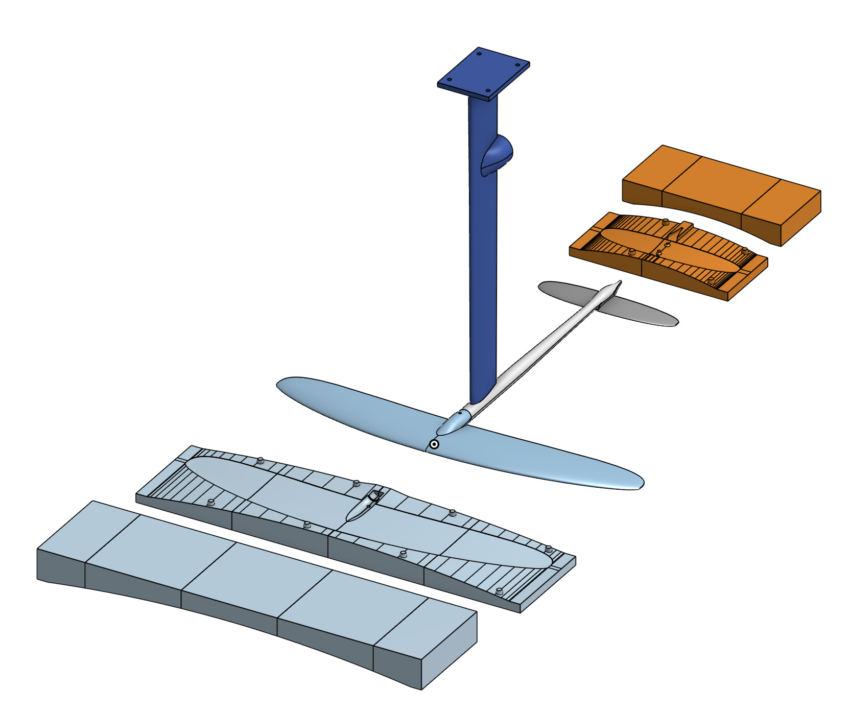
The foil model grew out of that nine-hour flight I mentioned and got a bit out of hand; it now draws the whole foil and generates the printable mold shells and layup schedule to build it in carbon. Different subject, so I’ll start a thread rather than clutter this one. The part that belongs here is that everything the mold feature had to learn, parting along the camber line so both halves release, printed keys, a pinch-off groove, holes molded undersized and drilled after cure, plugs taken off the part’s own cavities, applies straight to blades and a folding hub. A blade is sections along a radius instead of a span. So the blade generator could get a mold feature of its own, and a wet-laid carbon blade with the root fillets and pivot boss in one piece might be the answer to the layer-line failures you’ve had with printed ones.
A teaser, since the blade generator has grown a bit since the last post.
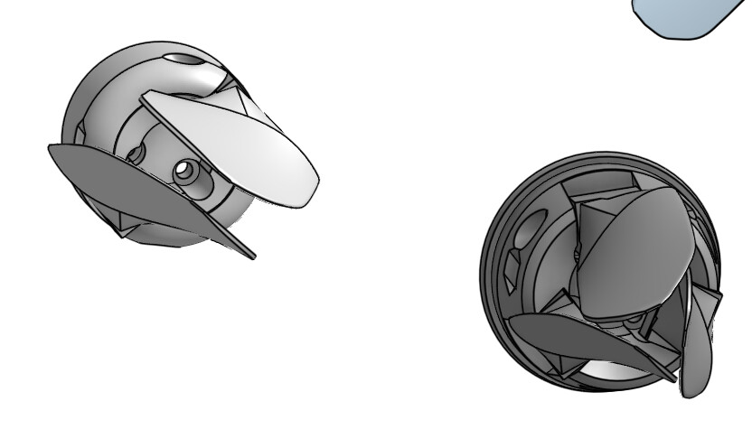
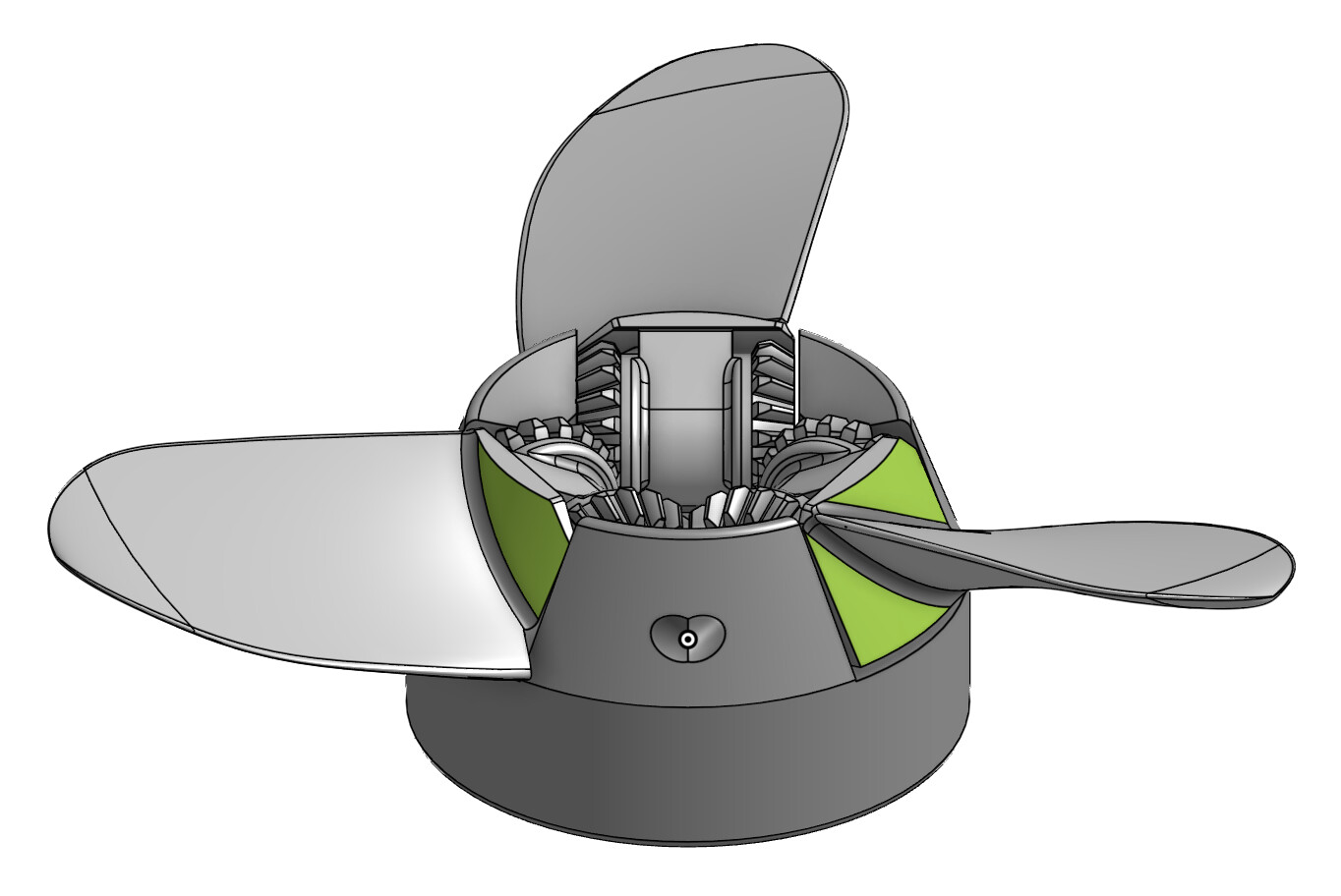
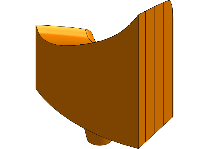
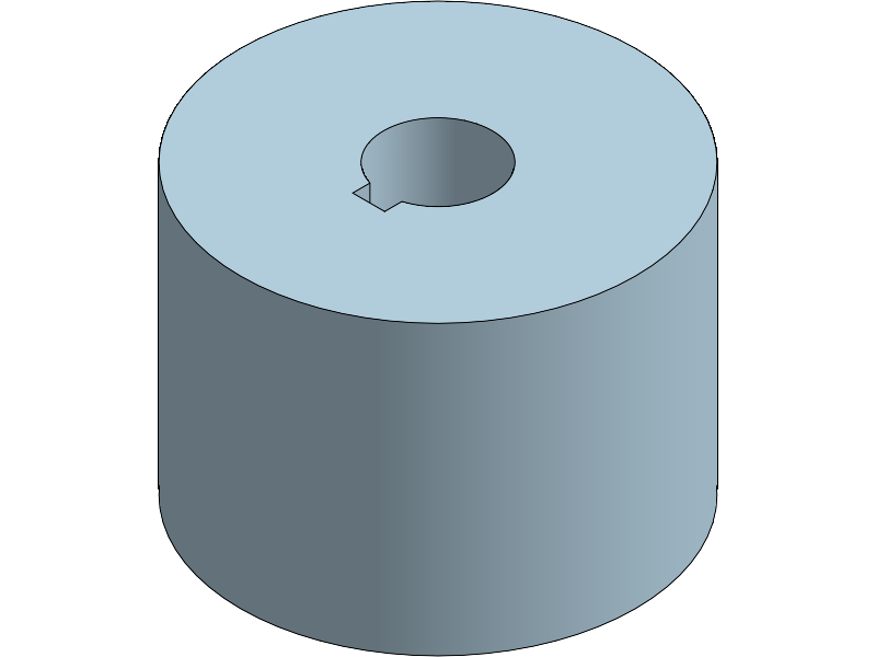
It’s about to build the whole propeller, not one blade. Fixed props with their hub, any blade count from two to seven, and folding props with the pin, the boss and tongue, the stop, and the relief round the tail so the blades clear the hub through the fold. Mounts for a plain bore, a keyway or a bolt circle. The picture is what it makes today from the same set of dialogs:
The folding hub is the part that took the work, and what shaped it came from this thread’s printed hubs and blades: no fairing on the blade roots, trim the blade not the hub, the blade root follows the hub’s own profile, and the fold relief runs all the way round the tail. It builds that way now.
The operating check has been corrected too. The motor torque constant read 13 % low against the datasheet’s number, so it’s a field now, along with cell voltage under load, and the hub’s share comes off the thrust and torque so a 63 mm hub on a 140 mm prop reads right.
Still to do before it goes into the public document: the gears, and the mold feature for a wet-laid carbon blade. I’ll post here when it’s up; the one-blade feature stays as it is until then.
A digital twin for the prop generator, and what it says about a foil-assist prop on a 6384
Since the last update the generator has grown a digital twin: a Python model that builds the same blade the FeatureScript builds, from the same dialog fields through the same tables, and scores it without going near Onshape. I use it to iterate, then build the winner once in Onshape to check it folds and clears.
What it simulates:
What it does not: the free surface, ventilation, the board’s hull drag through the hump, a duct. The section polars are fits for NACA-like sections, not XFoil runs of each one. Open water, plus the pod.
How it checks out. Against the polynomials on the same geometry, within 7 % at static with the same efficiency curve. Against the root loads I worked by hand for the narrow_140 review, 65 MPa against 64. Against e-Foil Holland’s static pulls of twelve props on a 65161 (the test Kwint published in 2023), within about 10 % on the eight props whose shape is known, and it gets the P/D 1.0 to 1.2 group right where the polynomials read 15 % low. Two findings from the loads that I had not seen by hand: the folder’s weak part is the pin in bending between the cheeks, not in shear.
A folding prop for a foil assist on the waterproof 6384
The job: a 6384 at 140 kV on 12S (88 A burst, 59 A continuous, 35 mOhm, its 63 mm bell as the hub), on a Silk 1050 with a 135 stab, 100 kg all-up, motor in for the take-off and folded for the glide. I swept 150 props (130 to 240 mm, P/D 0.7 to 1.1, two and three blades) and scored them at the take-off first, static thrust and thrust at 10 and 12 km/h at the burst, with the cruise as a limit, the top speed at the continuous current, the root and pin strength, and the folded blades’ wetted area.
Two things came out that I did not expect.
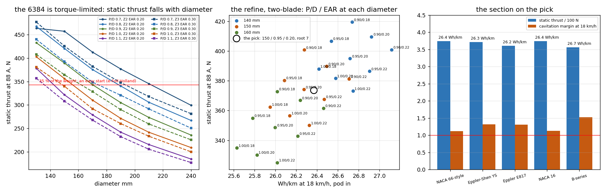
static thrust against diameter, the refine round 150 mm, and the section on the pick
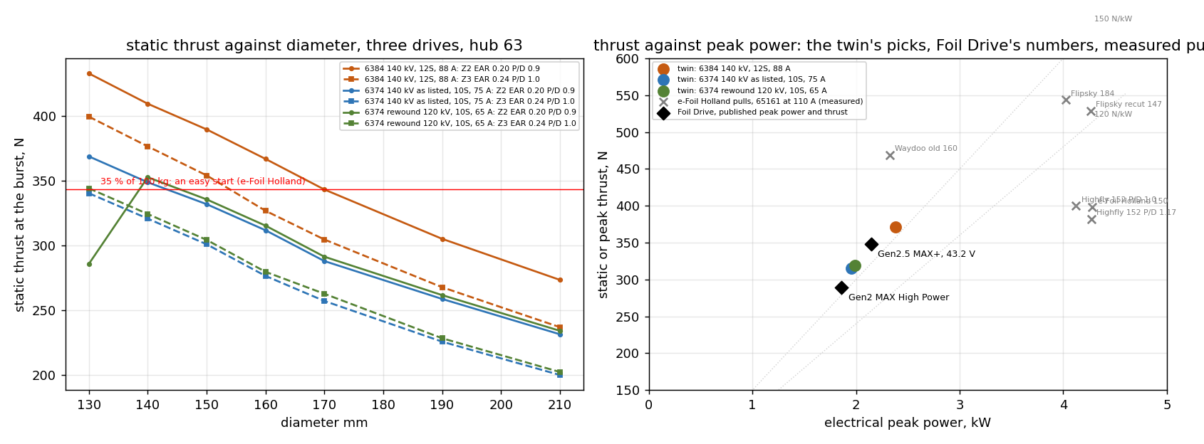
The 6384 at 88 A is torque-limited, so a bigger prop pulls less, not more. At P/D 0.9 a 130 mm two-blade makes 465 N static, a 150 mm 390, a 190 mm 305, a 240 mm 235. Everything over 210 mm failed the take-off or the top speed. 150 mm is the size.
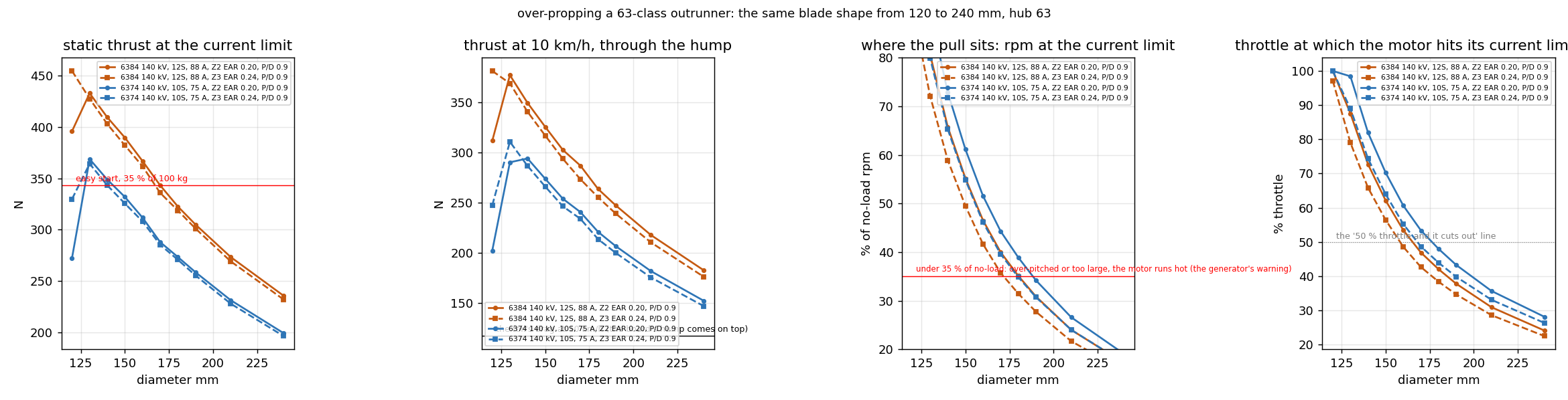
That is worth a chart of its own, because I think a lot of builds here are over-propped. Same blade shape from 120 to 240 mm on the 6384 and on a 6374, all at the motor’s current limit: the static thrust falls with diameter, the thrust through the hump falls with it, the pull rpm drops from 80 % of no-load at 130 mm to 30 % at 190 and under 20 % at 240, and the throttle at which the motor reaches its current limit drops from 90 % to 40 % to 25 %. A 190 mm prop on a 63-class motor is a motor at a third of its speed, full current, and an ESC that clips at 40 % throttle. That is the “horrible sound and it cuts out at 50 % throttle” from the 10S 6374 thread, and it reads as a weak motor when it is a prop the motor cannot turn. The bigger-prop instinct is right on a motor with torque to spare; on these outrunners at the burst it is backwards. The generator’s operating check warns under 35 % of no-load speed for exactly this.
over-propping: static and hump thrust, the pull’s rpm as a share of no-load, and the throttle at which the motor hits its current limit, against diameter on the 6384 and the 6374
And the cruise energy hardly moves across the whole sweep, 25 to 27 Wh/km at 18 km/h, so the choice is made at the take-off and the folded drag is a rounding error (under 1 N at 18 km/h).
The picks, the same prop with two blades or three:
| Two-blade, EAR 0.20 | Three-blade, EAR 0.21 | |
|---|---|---|
| Geometry | 150 mm, P/D 0.95, YS-920 2 %, 7 mm root, tip pitch -10, rake 15 | the same |
| Static at 88 A | 371 N (38 % of the all-up weight) | 371 N |
| 12 km/h at 88 A | 299 N, 214 N over the foil’s drag | 299 N |
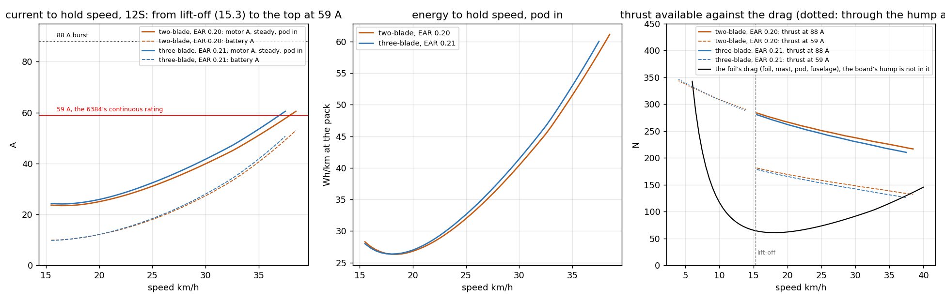
| Cruise 18 km/h | 26 Wh/km, 24 A, 44 % throttle | 26 Wh/km, 42 % |
| Cavitation margin at cruise | 1.3 | 1.3 |
| Top at 59 A | 38 km/h | 37 km/h |
| Root factor in PPA-CF | 4.8 | 4.9 |
| Pin bending factor, 5 mm stainless | 7.6 | 11 |
They are the same prop in the water. The two-blade folds flatter and is two of everything; the three-blade loads each pin a third less, turns 5 % slower for the same pull and is smoother past the mast. The YS-920 over the NACA 66 is for the cruise cavitation margin, 1.3 against 1.1, at the same thrust and energy. Both built in Onshape with no warnings and clear the hub folded to 90°. Kwint’s test put the line for an easy start at about 35 % of the all-up weight in static thrust; these sit at 38 %.
current, energy and thrust against speed for the two- and three-blade on the 6384, pod in, from lift-off to the top at 59 A
along the blade at the pull and at cruise: angle of attack, lift coefficient, cavitation margin and stress
For comparison: a 6374 on 10S
The 6374 comes up here as the Foil Drive’s motor: e-Jetter’s 2021 guess was a 6374 at 120 to 300 kV on 6S. What Foil Drive publishes since then is the battery voltage, not the motor: the Assist Plus and the Gen2 Slim run 8S (28.8 V nominal), the Gen2 MAX 40 V (11S), the Gen2.5 MAX+ 43.2 V (12S), and the MAX+ is rated 2150 W peak and 35.5 kg of thrust. So none of them is 10S; 10S on a 6374 is the DIY convention on this forum, and that is what I ran. Flipsky’s waterproof 6374 is listed at 140 kV only (2400 W rated, 3600 W max, 50 A rated, 75 A max, 44.9 mOhm; 120 kV is a custom order), so I ran the motor as listed, and the 120 kV rewind with the same copper (65 A burst, 45 A continuous, 61 mOhm) for comparison.
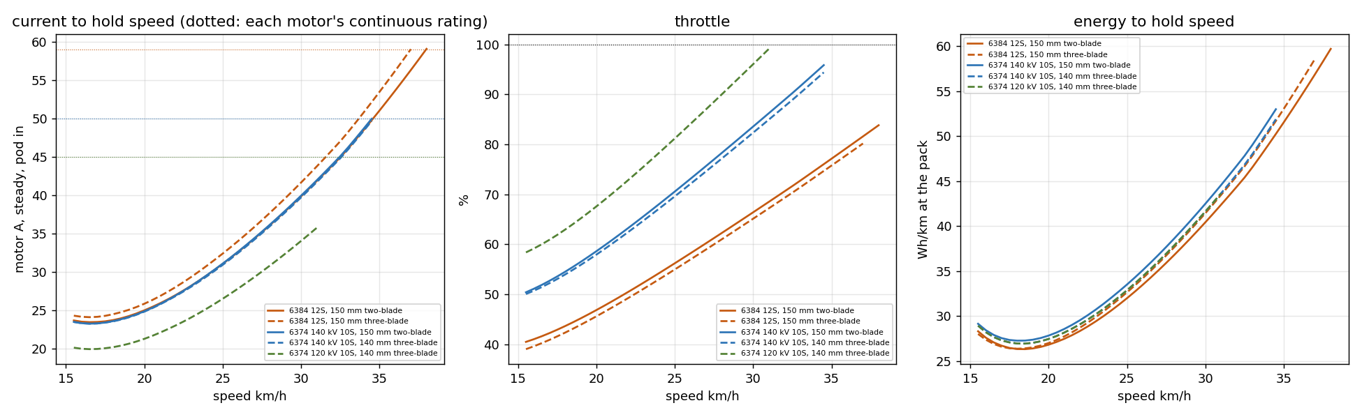
Torque at the limit is nearly the same as the 6384’s, 5.1 Nm against 5.9, so static thrust is only 15 % down. The difference is the pack: 10S gives 30 % less no-load speed, which pushes the pitch up and the top speed down. The same sweep, 216 props, picked the same two shapes on both windings:
| 6374 140 kV as listed, 10S: 140 mm, P/D 1.0, EAR 0.24, three blades | the same prop on the 120 kV rewind | 6384, 12S: 150 mm, P/D 0.95 | |
|---|---|---|---|
| Static at the burst | 316 N (32 % of the weight) at 75 A | 319 N at 65 A | 371 N (38 %) at 88 A |
| 12 km/h at the burst | 253 N, 168 N over the foil’s drag | 257 N | 299 N, 214 N over |
| Cruise 18 km/h | 27 Wh/km, 24 A, 54 % throttle | 27 Wh/km, 20 A, 63 % | 26 Wh/km, 24 A, 44 % |
| Cavitation margin at cruise | 1.3 | 1.3 | 1.3 |
| Top at the continuous current | 34.5 km/h at 50 A | 31 km/h at 45 A | 38 km/h at 59 A |
| Root factor in PPA-CF, pin factor | 7.1, 14 | 7.0, 14 | 4.9, 11 |
| Range on 10 Ah, motoring | about 12 km | about 12 km | about 15 km |
The two-blade for the 6374 is 150 mm at P/D 0.9 and EAR 0.24: 313 N, the same energy, top 34.5 km/h. The listed 140 kV winding is the better of the two on 10S: the same thrust with 8 % more top speed and more throttle in hand, because it keeps the no-load speed; the rewind only trades amps for volts. Because the rev ceiling is low, diameter matters less than on the 6384: everything from 130 to 160 mm pulls 305 to 325 N, the motor sets it. The three-blade edges the two-blade because it turns slower for the same pull. At 32 % of the weight it is a medium start, not an easy one: the rider pops the board rather than rides it up. 12S on the same motor gives most of the top speed back.
current, throttle and energy against speed: the 6374 picks on 10S beside the 6384’s on 12S
Set against what Foil Drive publishes, the pulls line up. At a static pull the motor sits well under pack voltage (the rpm sets it), so the 6374 at 75 A is a 2.0 kW pull for 316 N and the 6384 at 88 A a 2.4 kW pull for 371 N: 155 to 160 N per kilowatt. Foil Drive’s Gen2 MAX High Power is 1.86 kW for 289 N and the MAX+ 2.15 kW for 348 N, 155 to 162 N/kW. The e-Foil Holland props on a 65161 at 110 A measured 120 to 135 N/kW, bigger motor, higher pitch. So the twin’s 6374 case sits between the two Foil Drive units in power and matches them in thrust per kilowatt, which is as close to a check on the Foil Drive’s motor class as the published numbers allow.
static thrust against diameter for the three drives, and thrust against peak electrical power: the twin’s picks, Foil Drive’s published points, and e-Foil Holland’s measured pulls
What would help most now is water data: a static pull on a scale from anyone running a 6384 or a 6374 with a known prop, and a VESC log through a take-off. The twin is calibrated on Kwint’s twelve pulls and one log of mine; every pull added tightens it.
I run all my motors ( BDUAV 6384, Flipsky 6384, Flipsky 6374) with 105A phase current.
But with 2000W power output limit.
Less current is less effective since the motor stays longer in the acceleration phase .
Hey Jan, yup, getting over the hump quickly is definitely the way to go. Hanging out in that high-drag transition phase just wastes battery and cooks the motor. Most ESCs have a burst rating or boost feature you can lean on for a few seconds to force it onto the foil.
Since the VESC Tool uses an embedded Lisp dialect (LispBM), you can actually write a custom script to automate a power budget and recovery cycle. For example, you can safely pull 170A out of a 150A continuous-rated ESC for that short burst to get on plane, and then have the script scale back the thermal limits while you cruise and reset the budget
How the prop model works, and how much of it is AI
Nobody has asked, but since a few of the numbers I post here come from “the model”, I think it’s worth saying what that is and what it is not.
The generator builds the physical prop from parameters. The B-Series Propeller Blade Generator is a FeatureScript feature in Onshape. You fill in a dialog (diameter, pitch, blade area, blade count, section, camber, thickness taper, tip chord, skew, rake, the hub and the folding parts) and it builds the actual blade and hub you print. Change a parameter and it regenerates. It is the same idea as the Foil Design Tool in the other thread, for the other end of the fuselage.
It runs an operating check on that exact prop. Give it the motor’s kV, cells, current limit and resistance, and it reports thrust, torque, rpm, current, throttle and the cavitation margin at the pull and at cruise, with warnings (the under-35 %-of-no-load one is the “over-propped” warning). It uses the Wageningen B-series polynomials, which are open, seventy-year-old tank data.
Then there is the twin. A Python copy of the generator that builds the same blade from the same dialog fields and scores it section by section with blade-element momentum theory: tip and hub losses, the flow round the motor pod ahead of the root, the section’s own polar, cavitation at every station, and the loads on the blade, the folder pin and the hub. It runs in seconds, so it can sweep a design: every section the generator offers on one outline, every diameter at its best pitch, two-blade against three, each on a given motor and pack. That is where the over-propping chart earlier in this thread came from, and the section ranking for a racing prop.
What it has been checked against. Kwint’s twelve static pulls on a 65161 at 110 A (the e-Foil Holland test): the twin reads within −16 to +11 % on the eight props whose shape is known, and ranks them as the test does; the polynomials read 15 % low on the P/D 1.0 to 1.2 group. A racing rig’s VESC log at 50 km/h: the twin’s torque 7 % over what the logged current implies. The generator’s own check: the twin sits 5 to 10 % above the polynomials with the same efficiency curve. What it has not been checked against: anything cavitating. Above about 50 km/h the polars assume attached flow, so the ranking of sections there is from racing-prop practice, not the model.
Where the results come out. The notice under the feature, and the console report with every input and the operating check as text. Paste them into an AI with the assistant skill from the download, or into a message here, and the numbers can be read back and argued with. That loop, tool to text to AI to a changed parameter, is how the props in this thread were tuned.
How much is AI. The methods are textbook: B-series polynomials, blade-element momentum, motor algebra. The code, the generator and the twin, was mostly written by Claude from my specifications; I test it in Onshape, print the parts and publish it. Running the sweeps and drafting the posts: Claude. What to build, what to believe and what to post: me. It gets judgement wrong sometimes (the torque constant read 20 % low on static thrust until Kwint’s pulls showed it), and a measured pull or a log beats a thousand runs. If you have a static pull or a log from a prop you know the shape of, that is worth more to this thread than anything the model says.
Update: the generator now makes a printed mold for a one-piece carbon prop
The printed blades in this thread fail at the root, and the carbon-blade note I posted earlier said the simplest carbon prop is blades with flat tangs laid up in their own two-part molds and bolted into a printed hub. That still holds as the first carbon part to make. But the thing I actually wanted was a whole propeller, hub and blades, laid up as one laminate in one mold, with no joint at the root. The generator can now build that mold from a fixed prop it has made. Nothing has been printed or laid up yet; this is the design and what the model says about it.
Why it is not just two halves
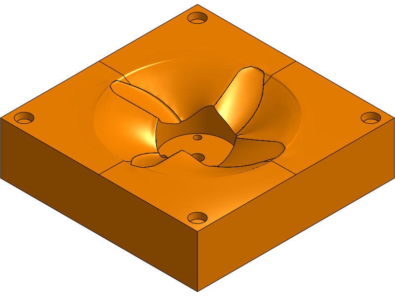
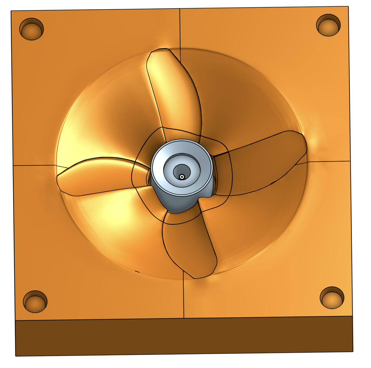
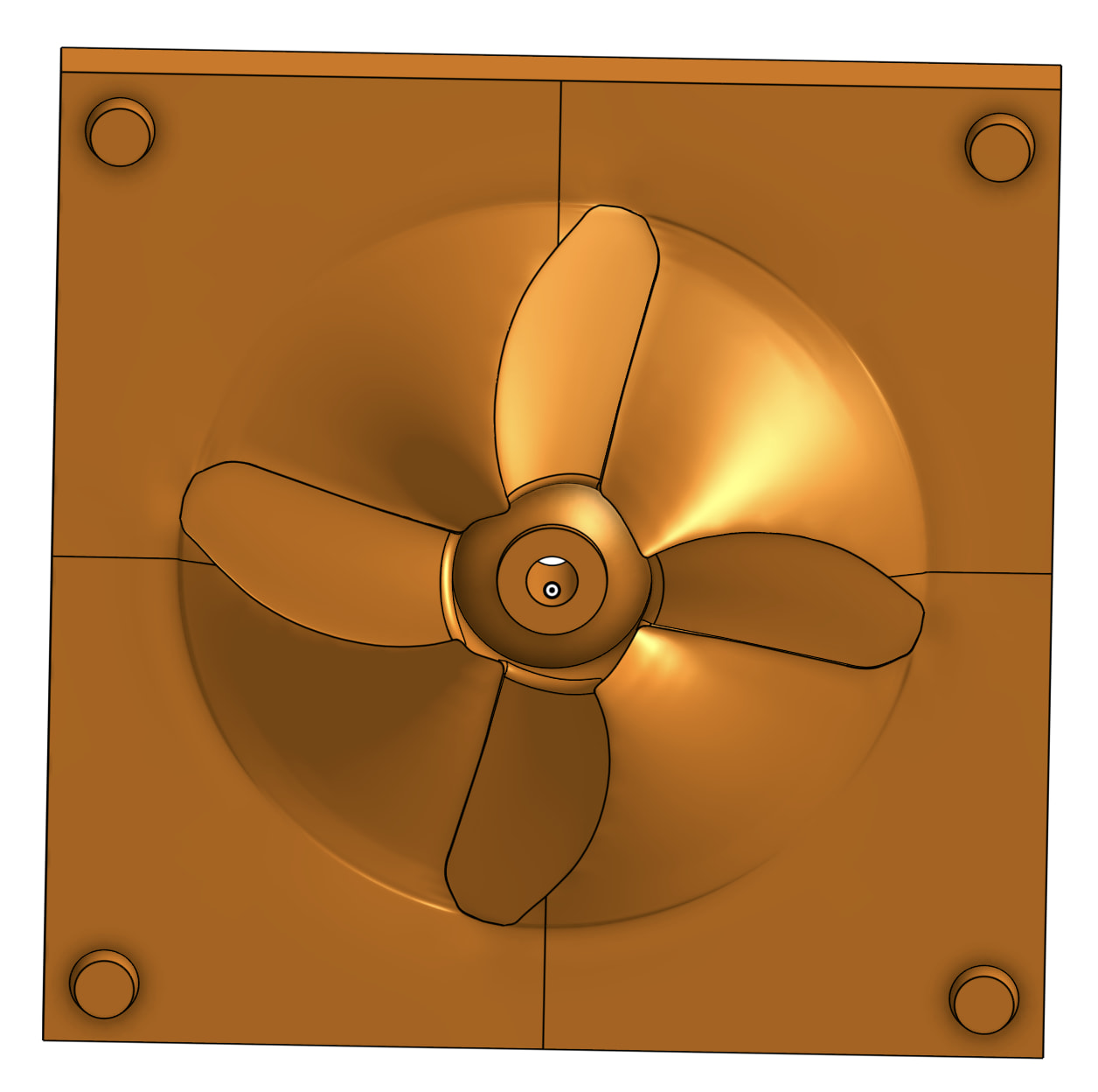
A wing mold is two halves parted on the mean line, seams on the leading and trailing edges. A prop is nearly that: every blade surface releases along the shaft axis, because the sections lean (42° at the hub, 19° at 0.7R on the four-blade I used) but never past vertical, and at EAR 0.35 the four blades do not overlap in the axial view. So a nose half and a tail half, each parted on the blades’ own mean surfaces, form all of the blades with the seams on the edges.
The hub is the problem. Beside each blade root the hub’s side sits in the shadow of the root’s own chord, a triangle on the leading side and one on the trailing side, 17 to 19 mm tall. On the 150 mm four-blade that is 10 cm² in eight patches that neither half can reach, however the parting is drawn, and no fillet fills a shadow that size. The release check in the model finds exactly those patches: 183 cm² of part surface, 87 formed by the nose half, 75 by the tail half, 11 parallel to the pull (the bore and the hub near its big end), 10 hooked.
The pieces
Two halves, pulled along the axis. Round the hub, a well, and in it a ring of radial sector pieces that form the hub’s sides: a root sector under each blade, forming the whole underside of its root and the hub beneath it, and a gap sector between neighbours. The sectors part at the blades’ edges, the same way the halves do, so the cloth is laid on one continuous bed from the hub out through the nose half. Each sector pulls outward along the mid-azimuth of its gap: the root surfaces are near-ruled by radial lines, so the sector slides out along them, and the check on a sector says 0.05 cm² hooks. The sectors key into the half they sit in. A rod through both halves makes the bore. Order of release: nose half up, rod out, sectors outward one at a time, part out of the tail half.
a root sector, pulled radially: it forms the underside of one blade’s root and the hub beneath it, with its key
Six to nine pieces plus a rod, one more than the three-piece-and-plug molds I have made for wings, and the sectors are small, about 10 cm² of face each, printed standing on their outer cylinder. The block for the 150 mm prop is 200 by 200 mm with a 25 mm flange, 72 mm tall, one tile per half on a 250 mm bed, roughly 1.5 kg of PLA and two days of printing for the halves, treated as every print estimate I post: a starting number.
The hub inside the laminate
A hub is a forged part, not a ply part. The 32 cm³ of solid hub in a 44 cm³ prop would need a piston with a 60 mm stroke to compact as chopped tow, and the blade halves cannot give that; they close through a few millimetres of plies. So the one-piece laminate wraps a core: a printed PPA-CF hub body, the generator’s hub inset by the skin thickness, about 1.5 mm for three woven plies, carrying the bore, the keyway or shear-pin slot and the dish pocket exactly as the printed prop does today. It stays in the part. The generator makes it as an option on the propeller, and the mold’s layup line reports what goes round it: laminate volume (part less core), about 60 g of carbon, the plies at six radii from the section thickness (one woven ply each face and UD between, about 18 plies at a 7 mm root thinning to 3 at the tip), the three-ply hub skin, and the resin to mix at 50 % fibre volume plus 4 % overcharge.
the printed hub core the laminate wraps: the hub inset by the skin, with the bore and keyway
Each blade’s root plies splay onto the core as tabs over the shadow triangles, alternating blades so the tabs interleave, and the hub plies go over the tabs. The sectors go in first against the core and the tabs, then the halves close on the blade edges and the hub ends.
What is not done
The pinch-off groove along the blade edges, which the wing molds have and this one does not yet. The sectors’ own release check (the halves have theirs). And the water: no mold printed, no coupon, no prop. The order I plan is a sector-and-key pair first, to check the fit and the release, then the halves, then a single blade laid up as a coupon in the blade part of the halves before any hub, then the prop.
Two things I learned building it
The parting cannot be lofted as one surface through the nested loops of all the blades; Onshape refuses it every time. It works as the wing molds work: the parting sampled on radial sections every 5° and lofted into a solid lower tool, then the block split on it. And the sectors had to be cut by thin slabs along each blade’s edge lines rather than by planes, because a plane cut is infinite and took the neighbouring sectors with it.
The propeller feature and this mold are still not in the public document; the one-blade feature is what is there. I will post when they are.
If anyone has laid up a one-piece carbon prop, or a blade in a printed mold, I would like to hear what the root did.