Processing: Blade Loop.stl…
First design attempt…
Not really sure about the blade angles though

That’s pretty, the curve on the blade is very nicely blended! What software did you use to make it? Is it just a swept profile with rails?
I was just modeling my own attempt, but using offset blade profiles with a loft in Autodesk Inventor doesn’t look the best.
I use Fusion360. Made five individual profiles: Inner two, outer two and the vertical connection. Then loft with guide splines.
This is ready for a test but I don’t think I’ll get out this weekend because of the weather.
All sanded and the inconsistencies in the aerofoil have been filled and smoothed to give it half a chance
Will those sophisticated propellers pass the first minutes of water testing ? We 're back to Oct 15, 2017 where this forum was created, post processing (carbon fibre layup , …)
However, something has changed: we have the 5-axis 3D printing for printing loops and curves in the strongest direction :
Who will (will there) be the first company to offer one that is molded ?
One that can prove the efficiency of the prop justifies the cost. Hell we’ll probably anti-gravity boards before they truly prove the efficiency of the sharrow prop is worth the investment.
You’re probably right in that. Looking at the loop profiles i doubt the benefit.
Large wetted surface, areas with drag but not lift and the main advantage as i understand it is the decrease of the tip vortex. How much efficiency can be gained back by that?
For out purpose its pretty easy to just use sintered props. Polyamid works just fine. That’s my plan. Also ABS FDM is quite good. Sanded + smoothed + painted of cause.
My normal props made that way hold up very good:
That’s a beautifully finished prop! Is it FDM
That looks like a foil-assist setup…
Yes, wrote that
No, 3kW eFoil
Yeeeees that is what I mean, can’t wait for the first results.
Do you got a file for free CAD that I can adapt for my motor? Thanks for sharing.
I did a better caeses based prop variant with a good loop and profiles which follow the normal propeller path. I think i got the axes of both lower and upper blade skewing right…
It doesn’t add much useless area in the loop so I’ll try printing this one.
Looks like the foil is upside down on one side?
No, all profiles are as they should be. but they are all on individual planes, so it looks confusing when viewed only in 2D.
Nice! Sounds like I just need to adjust the angles of my sketches a bit to get a better curve.
Did you have a specific profile that you were using for the blade? Or was it just a guess? I just drew a cord and two splines with a single control vertex each and made sure one edge was a little longer than the other.
I did another variant of the loop prop, i thought my last one looked OK but the hub was too long, really happy with this one. Now if only i had a metal 3d printer 
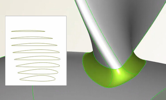
I can see you’ve thickened the blade roots on the hub (called filets) as seen on the CAESES site
Ship Hull Design with CAESES › CAESES. Oddly enough, the site recommends thickening the profiles as follows…

but their best optimisation - the FR prop - has thin blades with minimized roots and filets…
![]()
It is possible to print that with an SLS printer in PA12?
Or do you think that the blades are to thin for this material?