That means Rx firmware is uploaded to a Tx board
Please upload Tx firmware according to the video I made
Sorry, I made a mistake in the line.
I’ve now updated TX again and now it works.
2 Likes
Was just trying to find some information about the progress on that. I am about to assemble my V2 remote and realized I do not have the TX GPS.
I have not followed the development during the winter since I mainly focus on snow activities. But now spring is coming and dreams of water start to flow. My current tow boogie do not yet support steering but I guess any kind of unit that can be steered and the RX can be connected to would work for debugging/developing the Follow Me feature?
Hello,
My bremote is finally operational, the short circuit problems were supposed to be caused by an overly aggressive stripping flow.
A question: how to visualize the battery charge on the remote control screen when I connect the + of the battery to the “Meas UBAT” pin ? i dont see anything.
thank you.
You need to set data_source in Rx confog to analog and num_cells to the amount of cells you have (e.g. 14S pack = set 14)
Then the battery SOC will be in the bottom bargraph
Update:
Logger tested and working fine
As promised, the BREmote V2 Rx has the potential to log data
I have implemented and tested this.
How it works:
- connect BN-220 GPS module to Rx
- connect a VESC via UART
- send the command
?dbit4to enable auto-logging permanently - with
?dbit0you can toggle VESC debug data,?dbit1for GPS and?dbit2for logger debug data - as soon as GPS fix is made, the logger will record data
- when the Rx has no connection to Tx for some time, it will start a WiFi-AP you can log into
- go to 192.168.4.1 and donwload the logs to your phone
Compatible with logtrc
@Kian and his dad made this awesome log viewer you need to check out: LINK
It works with VESC and other log files too, as well as the BREmote logfiles.
Here an example of one of my logs: LINK
All files on GitHub, Rx software V2, so you can simply update without losing any settings. Upload the .ino.bin to 0x10000 like usual.
Download here: LINK
Enjoy and let @Kian and me know your feedback ![]()
5 Likes
Ludwig thanks for adding this functionality to the BremoteV2
Would it be possible to make a video demonstrating this functionality for the data logging with GPS?
Hello Ludwig, I have a remote flashed with the latest tx firmware, who doesn’t seem to respond to the cmd “?printInputs” Throttle and direction values stay at zero at all times.
I don’t know what to do. Everything is already sealed up with epoxy.
I built it few months ago, and in my memories everything was fine at this time. (Not 100% sure, though. )
The remote comes from the first batch one year ago and has never been used.
I hope there is something to try. ^^ Thank you.
Please do the calibration again
For that send a ?clearSPIFFS followed by a ?reboot
Then the remote will prompt you for a calibration, do that and send me the output of the serial monitor of that process
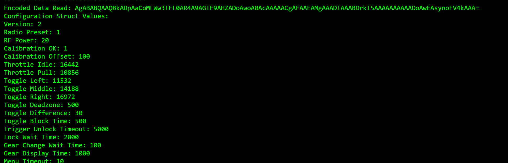
Thanks for your reactivity. I tried a clearSPIFFS, I did the calibration few times, Got the “save” message. And I have some values in ?conf (throttle idle/pull etc …)
But still nothing in “live” , ?printInputs , this is not good.
Again, please send me the calibration output and/or conf string… But if the calibration works and saves that’s a very good sign
Another thing you can try, connect remote to Rx, unlock remote, on Rx connect serial terminal and send ?printPWM
Thank you. Everything is back to normal. ?printPWM on Rx seems to work.
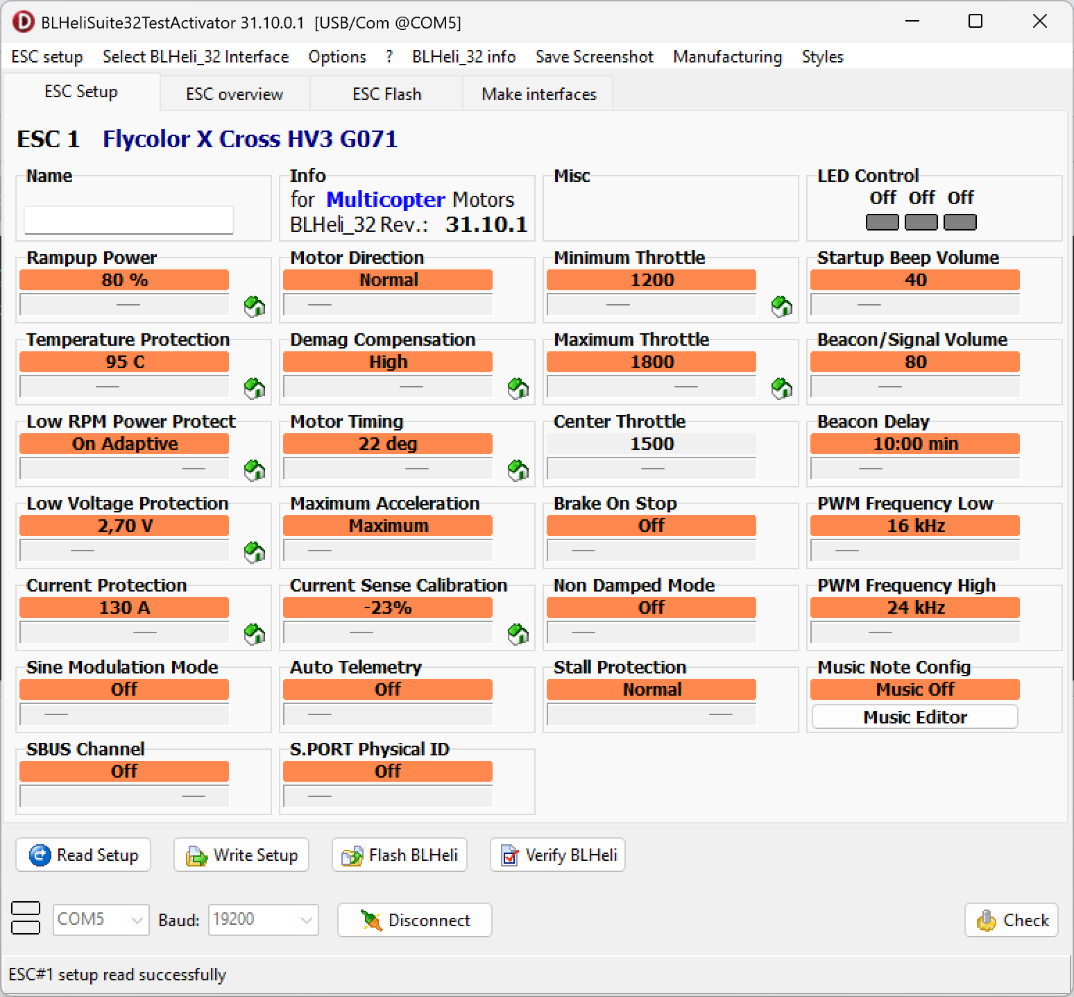
I spent six hours yesterday trying to figure out how can I connect the bremote to my ESC Flycolor X-Cross 160 A on BLHeli. I haven’t been able to move one engine.
TOW BOOGIE bi-motor
Bremote V2 + Rx&BEC
ESC flycolor X-cross 160A (X2)
2x BDUAV 6384 120kv
12S battery
Did I miss something?
On Rx set minPWM to 1100 and maxPWM to 1900 for BLHeli ESCs, then do the usual calibration steps according to your manufacturer
For most manufacturers:
Remote to highest gear, hold throttle all the way
Power on ESCs while still holding throttle all the way, motor should beep multiple times
Let go of throttle
Motor should beep again multiple times
Calibration done
If the motor does not beep the first time, change the PWMmax value and if it does not beep 2nd time change the PWMmin value, e.g. from 1900 to 2000 or 1800 for the max and 1100 to 1000 oder 1200 for the min
1 Like
Quick Question: I have a 12S battery sitting @46V so roughly at 50% capacity. When i connect it to the bremote RX only two dotts from the battery indicator are not lit. When booting the rx while connected via terminal it says something like 0% = 2.5 V per cell. Is that the reason why it show almost a full battery? Can i change that somehow? i want to have 0% at 3.3v.
In the default setting, 2.5V = 0%, 4.2V = 100%, linear
Best thing to do is to load the lookup-table (LUT) for your actual cells and expected load, alternatively I can send you a LUT for the 3.3V-4.2V values.
More info about LUT and battery calibration also here: LINK
hi @ludwig_bre, I got a kit an without a gps, but i changed my mind and i am looking to add a bn-220 module.
I have connected the gps on the uart as described in the github for VESC and enabled the GPS on the TX and RX configuration but so far i got no speed on the TX screen.
am i missing something?
?printGPS gives me the following even though the GPS has been booted for a while:
----- GPS Satellite Status -----
Satellites in view: 0
HDOP (Horizontal Dilution of Precision): Invalid
Location validity: Invalid
Date/Time validity: Invalid
Course validity: Invalid
Chars processed: 1303082
Sentences with fix: 0
Failed checksum: 0
Thanks in advance!
EDIT: I got it working, i updated the RX firmware to the logger, i am looking forward to test the logging features ![]()
1 Like
Happy you got it working
As background information, the firmware without logger is still expecting a NEO-6M GPS module, that’s why it was not working
BN-220 modules need the logger firmware
1 Like
Hi all,
Can someone please remind me how I can recalibrate left, right and centre on the Bremote v2? I already have it calibrated but want to do it again as think it is a bit off. I’ve checked the videos but can only see reference to the first time.
Many thanks.
Described on GitHub ![]()
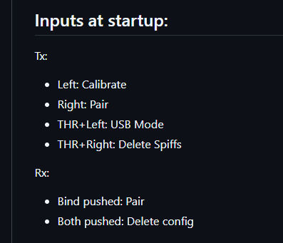
Option 1: Hold left toggle pressed while turning on
Option 2: Just set the “cal_ok” variable in the config to 0 and reboot
Perfect. Thanks Ludwig.
1 Like