Hello everyone, I would first like to thank you all for this great community and the knowledge and help you provide.
My plan was to have a functioning board for the summer as soon as possible after graduation. But as you know, I couldn’t wait until the exams were over because I was constantly looking at the parts, so I built it quickly over a long weekend.
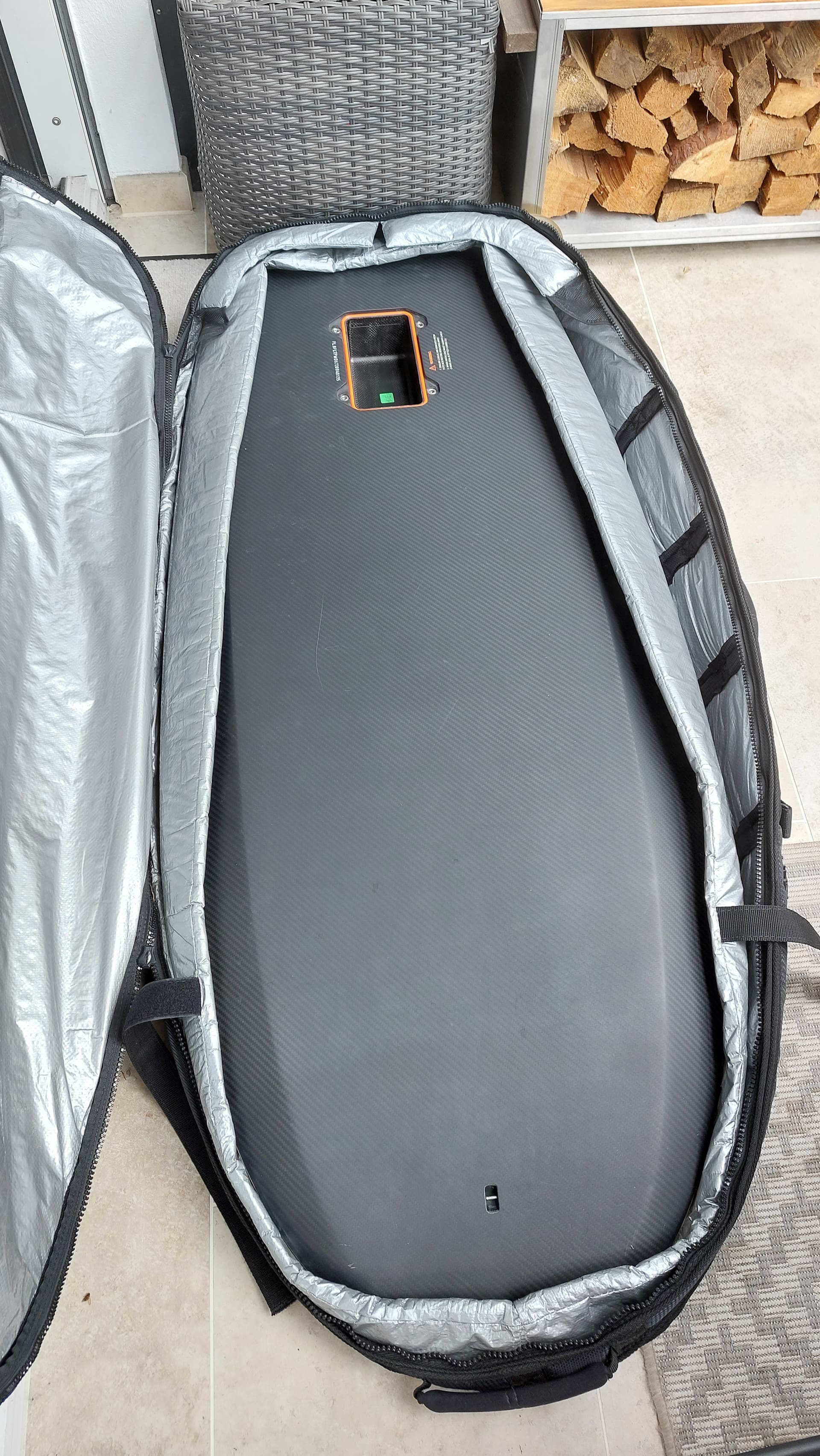
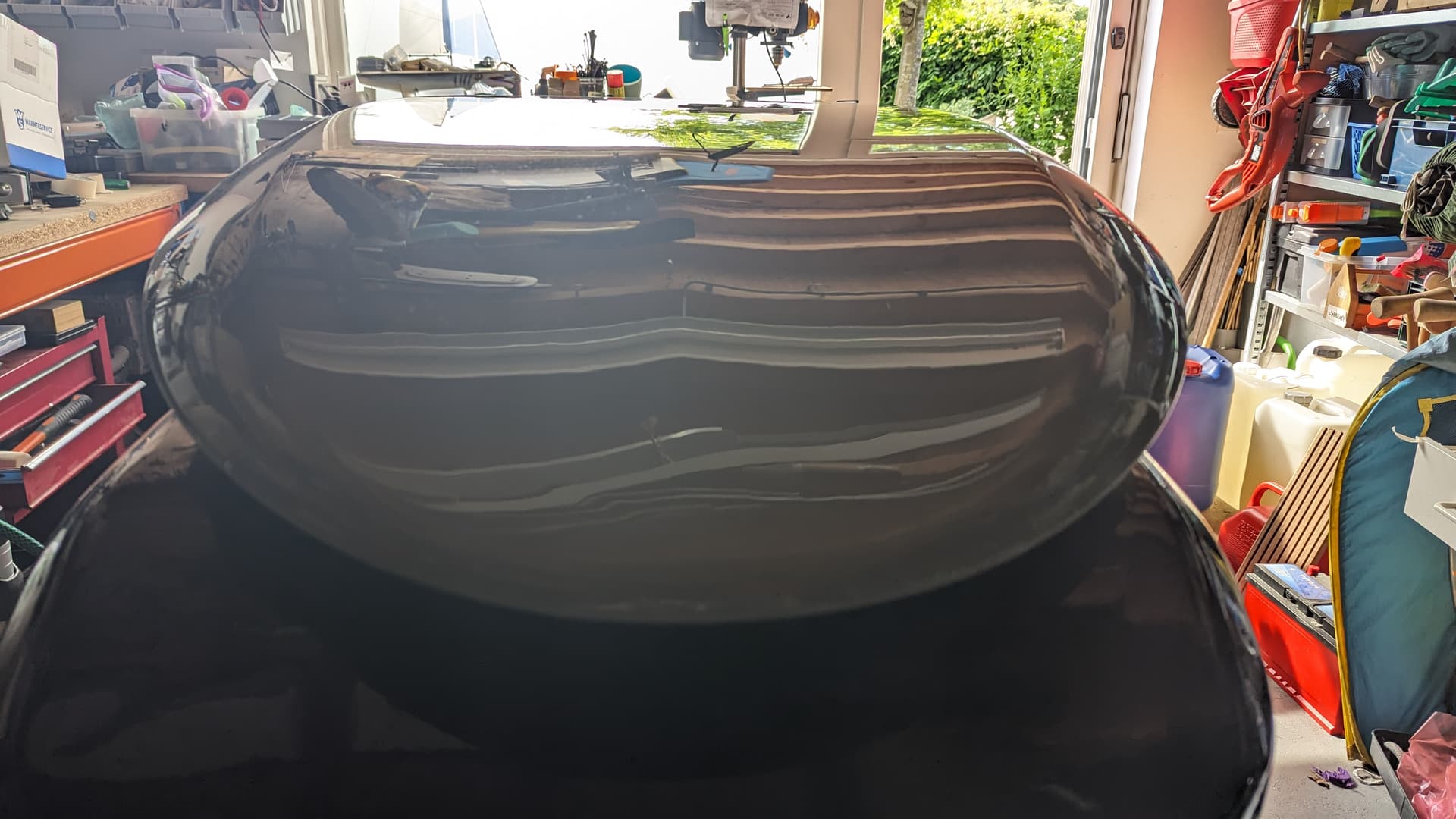
Even though many will now think that it is not a real DIY, I find the Fliteboards very beautiful. I got it for a very reasonable price, for which you can’t even build it yourself in this quality, and I also saved a lot of time.
Yes, I went the easy way, but in the end it works and you can customise it to your preference and it’s still fun to build.
I decided to use the typical components that have proven themselves here in the forum. The aim was also to spend only as much as necessary, as I don’t have a lot of money lying around as a student.
For the motor, I chose a 120kv Maytech 6516x with the ceramic seal, filled with medical white oil. Despite the exciting tests by @ludwig_bre , I went for oil without additives, as it also protects against corrosion, lubricates the bearings and does not contain any sulphur.
It probably doesn’t matter what kind of oil is used, because most of it is technical white oil anyway.
Before I finally milled the mast plate, I tested the Trampa VESC 75 300 with the motor. It produces a real sinusoidal wave. This makes the motor “noiseless” in the air and in the water, and it has more functions and delivers more power than the Flipsky. Nevertheless, I decided to go for the new 75200 with aluminium PCB, as it is much cheaper at 150€ and easier to replace if the Trampa breaks down due to condensation. I recommend the modifications by jaykup from the esk8 forum.
It is definitely audible, but nevertheless quieter than an original Fliteboard.
I decided against the 6inch three-blade FR propeller because it was too sharp for me with the aluminium. Instead I use the Fliteboard propeller that matches the board, which seems more harmless to me and is also supposed to be very efficient.
I decided to use a Maytech remote control,Instead of the often used VX3, as it is easier to handle and shows me enough information on the display. Of course, it was modified so that it would last more than just a few months.
And now to the actual construction
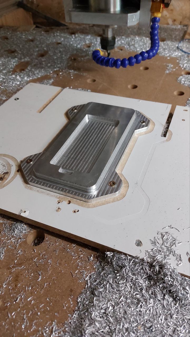
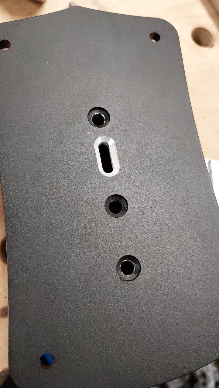
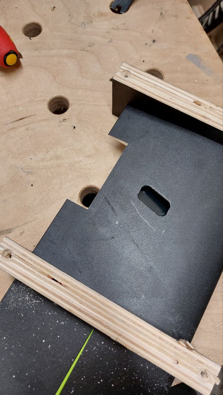
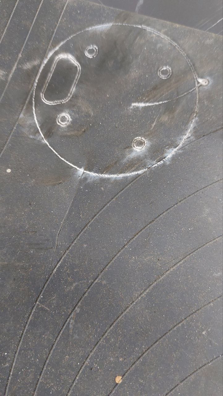
For the adapter plate I used the file from @MBard . However, the boards seem to have tolerances because the radiuses don’t exactly fit. So I had to do some more work. Next time I’ll mill a template out of wood first.
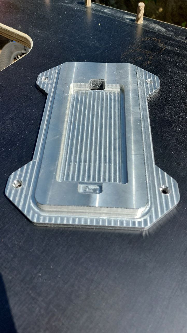
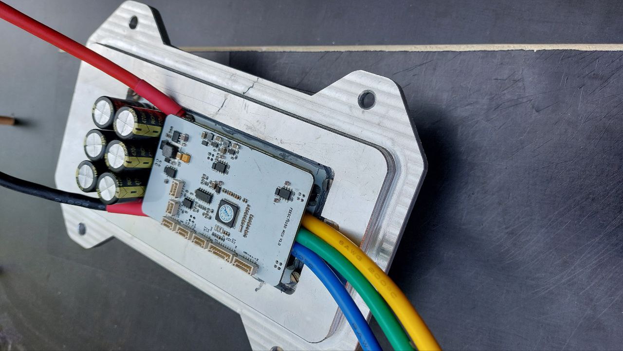
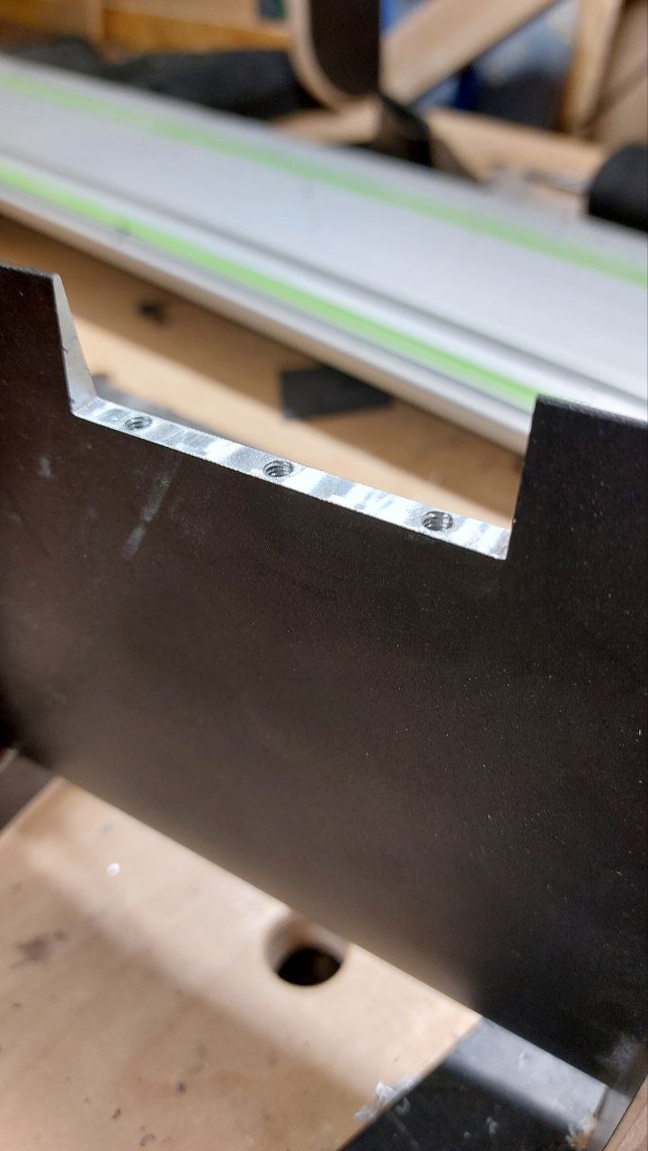
Unlike Marcel, I used a 12mm aluminium plate that I had lying around and removed the housing from the Vesc in order to have better heat transfer. To save weight, I recessed the VESC.
I didn’t put the cables on the side, but in the back, so that they don’t run under the mosfets. Next time I would also put them on the side, as the heat dissipation from the ALU PCB is outstanding.
I made the threads 11mm deep and also tightened them with Locktide. This is more than the minimum screw depth and should be stable enough. I used A4 70 stainless steel screws with countersunk head and Allen key everywhere.
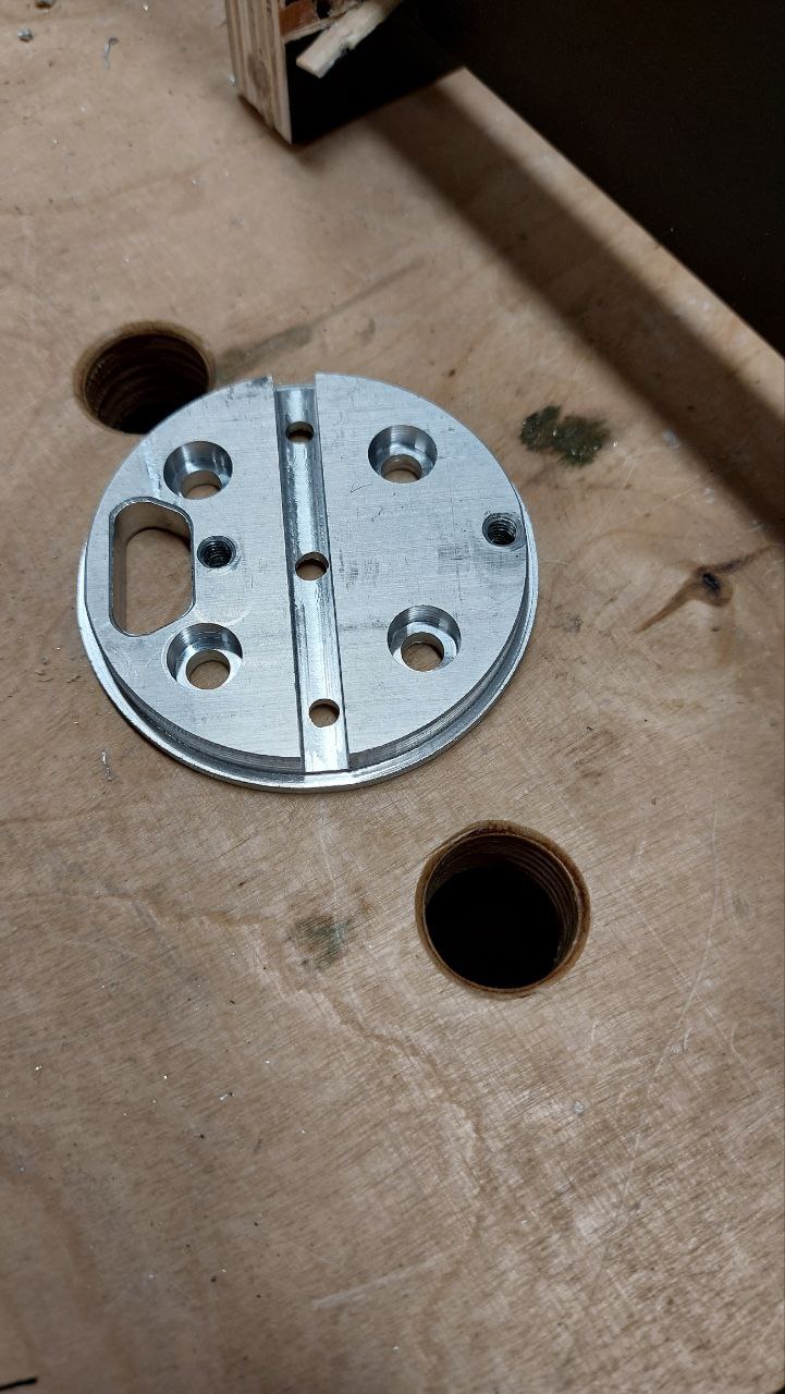
Next time, instead of the adapter plate and the mast plate, which I already had, I’ll probably mill everything out of one piece of 35mm aluminium.
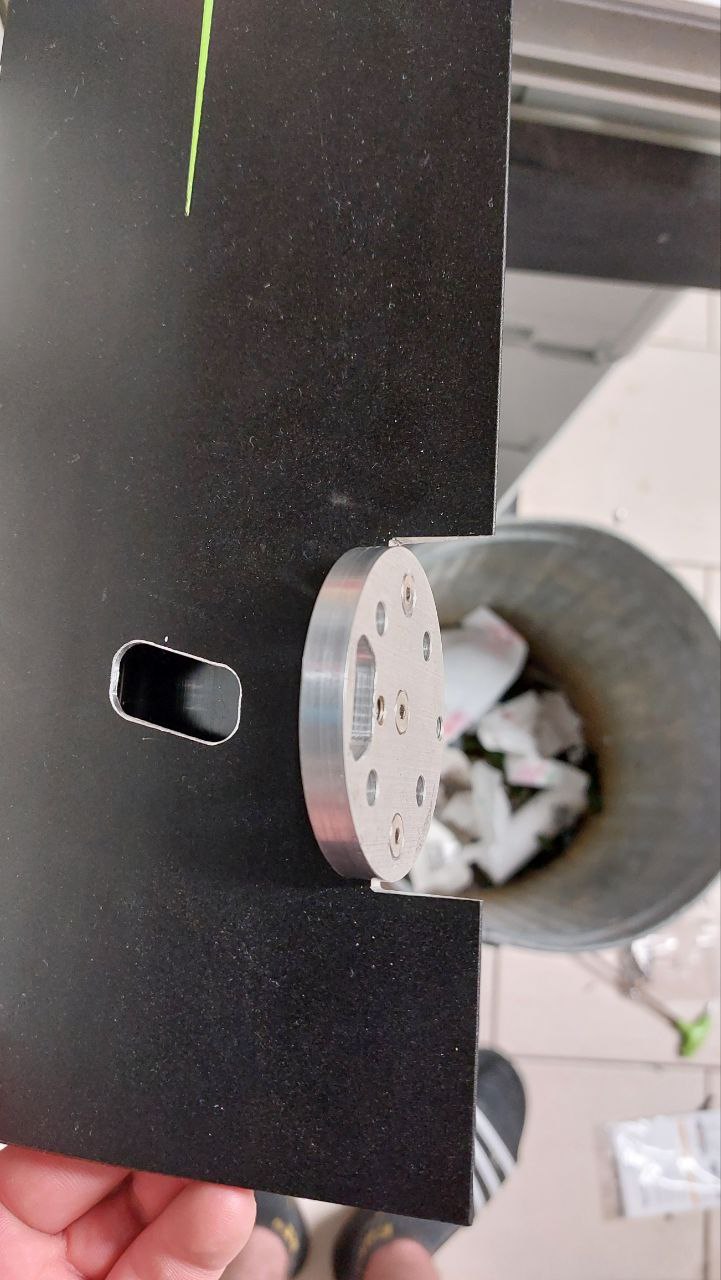
Originally, I wanted to mill a lid out of a 20mm PE rest for a slim design to protect the VESC from moisture.
When I saw at @t-dub-maui that you can get a finished ABS housing with a lid for only 4€, I decided against it. I removed the bottom of the housing and milled a groove that matches the contour of the box.
When I tried to replace the power cables going to the battery with longer ones, I found that a 150W soldering iron was not sufficient for AWG8, as the heat disappeared directly through the PCB into the heat sink.
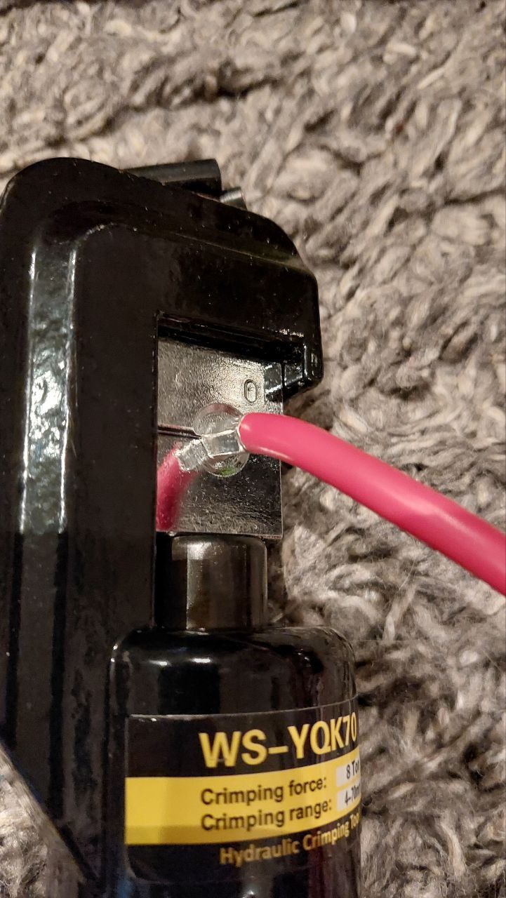
For the motor cables, however, I decided against the 8mm gold plugs, which are easy to solder. Since I wanted a gas-tight connection, where the cable still remains flexible(only 2cm). Therefore I crimped the cables with copper connectors, which is clearly more comfortable and easier than soldering. In addition, the resistance could be lower.
I have used XT90S on the battery, as I think they are sufficient. When driving relaxed it only consume 20-30A and 75A at the start. QS8 or AS150 allow more current, but are also larger. The Surlock are also not bad, but cost a multiple and the housing is waterproof.
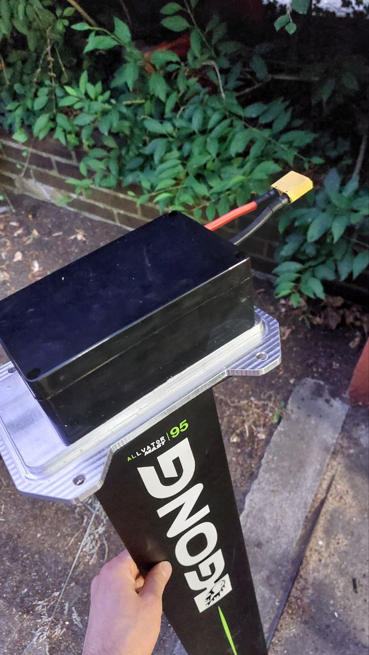
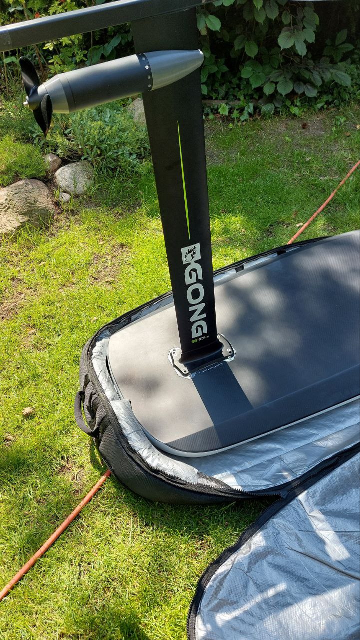
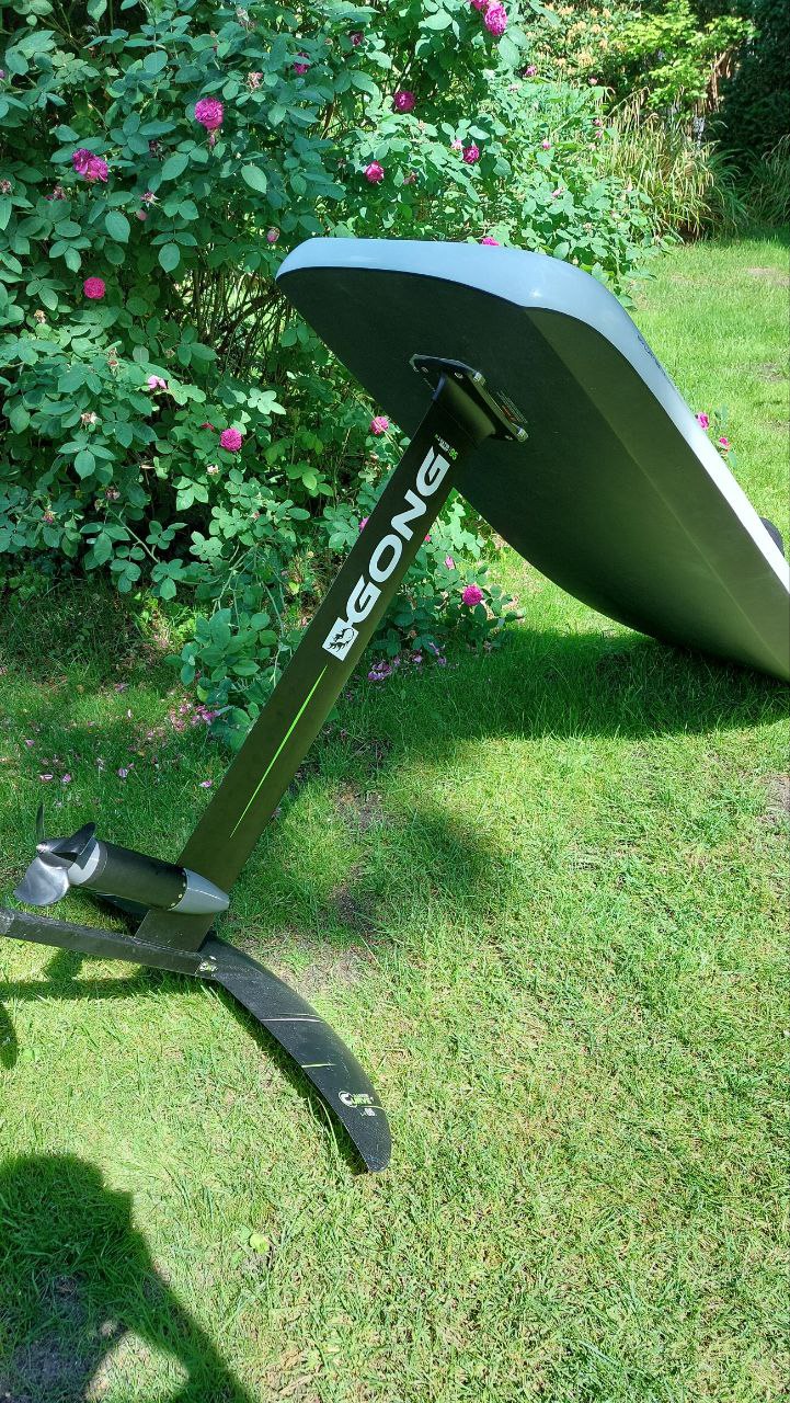
As a mast I used the common Gong 95cm V2 mast, because I also want to carve at choppy water and it simply offers much more freedom in tight turns, as long as it is deep enough. The stiffness is clearly noticeable in the weight. The 19mm Axis mast seems significantly lighter at the same stability.
But I decided for Gong, because the foils are now really good and the price is excellent. However, I can use all my existing wings, but no shims.
The mast offers more than enough space for cables and other things. A dynamic pressure cooling like @MBard does not seem to be necessary. At 29°C air temperature the VESC does not get above 37°C which is impressive.
I copied the motor mount from @Toto44. The first attempt I made with 12mm PP. It is easy to chip, but it gives a little bit so that the engine can be pulled 1mm to the side.
This was followed by an attempt with 3mm aluminum sheet, which was not better.
Currently I have a 6mm aluminum plate in use, which has a conical groove (5 °) and sits on the mast. I was hoping for more stability, but the motor can still be moved by 4/10 mm. Is this normal or sufficient?
For the nosecone, I played around a bit with CFD. But I doubt that it is the optimum, because neither mast nor propeller were taken into account.
To eliminate the vibrations of the motor caused by the cheap flipsky controller I lasered out a gasket. Questionable how much it brings, because the screws are in direct contact with the mast.
I decided against turning the propeller to 12mm on the lathe because it seemed risky in case it came loose and I didn’t want to crush it.
The tailstock wasn’t an option either, as I wasn’t sure if it was 100% vertical.
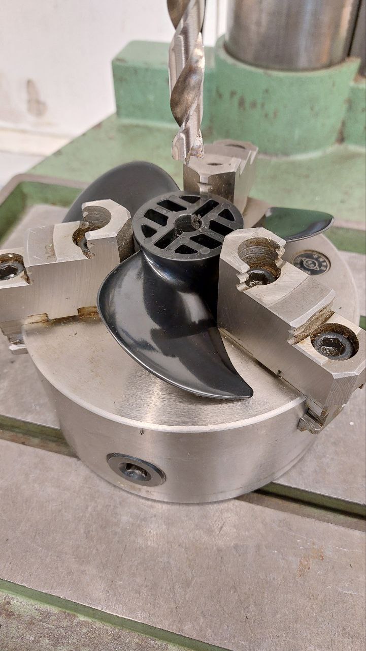
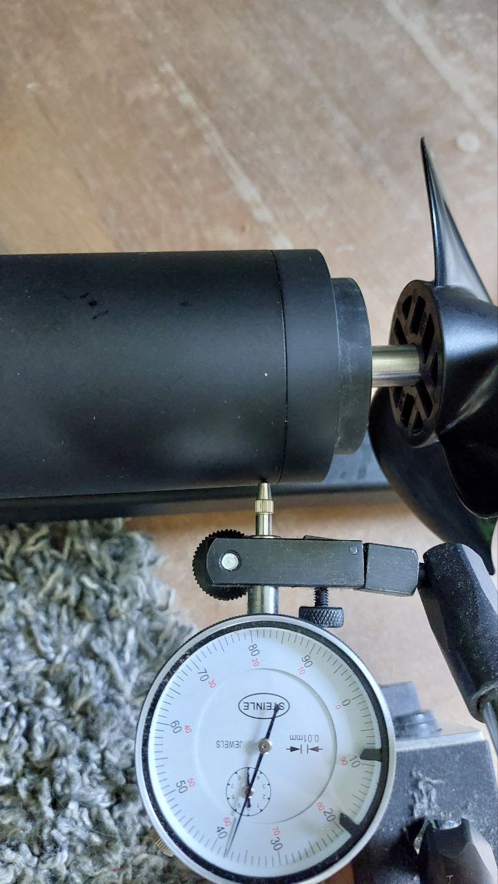
Therefore, I clamped the propeller into a chuck and aligned it with a dowel pin. With the dial gauge everything was checked again. Since I was now sure, it was easy to drill it with the drill press.
The whole effort was probably unnecessary, because the propeller sits on the pin and not on the shaft. Anyway, it fits perfectly and has no play and causes no vibration.
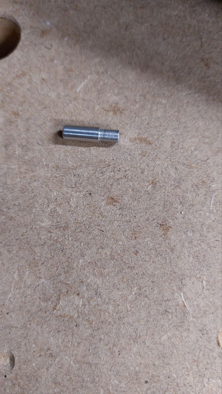
There were also several options for the pin. I decided not to bore the shaft to 5mm, as my other propellers have a 4mm pin. But I didn’t want to use a 4mm pin either, as I like to use reverse gear sometimes to avoid swimming to the board. So I just quickly cut the pin in half and turned the ends to 4mm.
At the beginning, I had the reciever in the electronics box without an external antenna. It was even possible to start it up, but the board lost the connection when water splashed over the board. To get a stable and reliable connection, I connected an external antenna. I shortened it to 125 cm so that it would fit perfectly in the reciever housing in the bow. There is a lot of space in the bow, so instead of the antenna you could also use a metr module and the reciever with a cable and JWPF connector through the 16mm tube.
In conclusion, I have a board that suits all my needs. Moreover, it not only looks good, but also works as it should. If you don’t take into account all the time and the workshop and machines I already had, I now have a board for 2 grand.
It was a great project because the machines in my workshop did something productive for me and so far everything has gone according to plan.
I would be very happy to hear your opinions and am open to suggestions for improvement and would be happy to encourage others to start as well. As you can see, it’s not particularly difficult if you choose a ready-made board. However, DIY is all about building the board, the electronics are actually no big deal as long as you know what you’re doing. You can definitely learn a lot from this project.
Thank you for your time and for reading it to the end.
The summer can come now