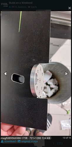
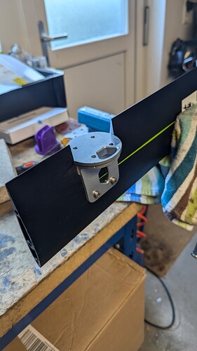
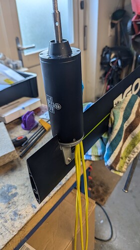
Wow, both of those look really nice. I imagine that integrated mast plate will really save some weight, but looks like quite a bit of CNC cutting!
@Kian Really great work. I would be very interested in the motor mount. Could you share the step file please. Pcb way?
Nice looking components. Is this for a new build or are you replacing components for your existing rig?
Looks like it was expensive, what was the total with shipping and taxes?
Sorry, I cannot post the price here, but since it was made by a friend of my dad who lives about 50 km away from us, and in his own time, it wasn’t too expensive.
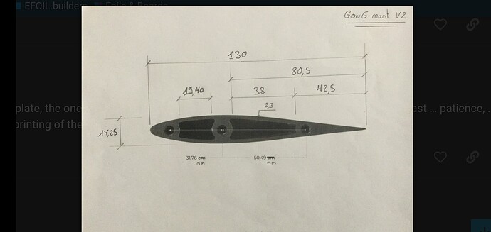
The thing is, the mast plate (where the Gong mast goes into the plate) has such tight tolerances that it needs to be test fitted after each CNC toolpath pass.
PCBway might have been a little bit cheaper, but they do not have a Gong mast ![]()
Also, when everything is fitted and tested, I (my dad) might sell some baseplates for around the €130 mark (depending how many are made)
@Kian I would order a groundplate for that price. How much is the motor mount? Can you produce it also for me? For erasing the tolerance I would use my diy skills😉Or maybe I could send you the mast if possible. Wright me a pm please.
No need to send me a mast. I have one here ![]()
As mentioned before, we will test things 1st before making more.
We already have 7 ppl who “ordered” the plate, so we are thinking of getting 10 made.
The motor mount is a different story as you are now the 2nd person who would like to have one. Make just one more is not interesting, and will end up being more expensive than the plate! (it’s actually harder to make!)
I will keep you updates as soon as I have more info!
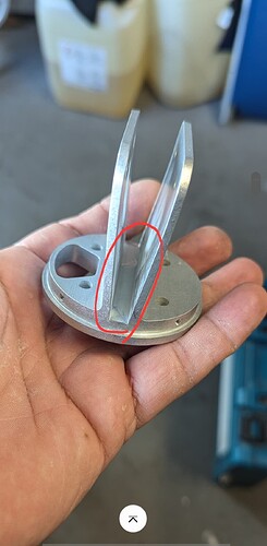
The motor clamp @Kian made is nice and simple, but it does look like a lot of cnc cutting to produce it. You could try this other mount and maybe get the equivalent part that interfaces motor and mast cnc cut. Would be heavier for sure, but less time to make.
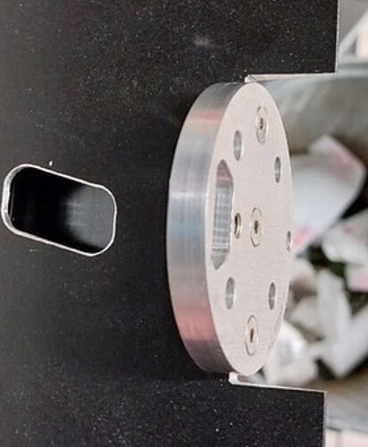
@foilguy I saw this picture already. Thats why I am asking. because if you look close enough you can see that there must be some cut out from the mast. Which I think is the best Position for the motor. So my question is if @Kian wants to srew it like that both ways, from behind and from the side. would give everything maximum stiffness. And to drill 3 extra holes can be managed without a cnc.
@S_Roger thank you for the link. There are many options to fix the motor. I am searching for the most stiffest one. I think this is only posibble with screwing it into the mast directly without any clamping and aluminium as the material. The mount @Kian father designed is nearly perfect for my needs, excluding the 3 wholes I would add from behind.
Well we could wait for Kian to tell us but I don’t see any reason to cut the back out of the mast to make this work. Just slide it on the back and the two ears resist any torque from the motor. The 4 holes at the end of the ears let you attach it in place
IIMO removing material from the trailing edge of the mast to fit a disc in isn’t a good way to go. Removing material usually weakens any preexisting structure.
You are wright, but strengh of the mast isn’t the reason for design the back edge like this. Its only for streamlining. But lets wait for kian, of course it works also with 4 screws only from the side. Even the plastic clamps work for most of us.
Your picture zoomed in. Clearly shows the trailing edge removed so the disc can sit against the rear most solid extrusion in the mast that you drill holes in to mount the motor mount disc.
So you are removing mast material in the same area as the wire holes, secondly and perhaps more important is the the disc only has support on its centre line. Conside a disc balanced on a narrow structure is less stable than the same disc sitting on a wider structure
Kian’s design doesn’t seem to have these issues.
I do t understand how the cutout disc design improves the streamlining over any other one??
The streamlining is meaned without the motor. This mast was never designed for motor mount. Does not depends which one.
Maybe here you can see what I mean with streamline edge.Or maybe not we will see.
I don’t want to hyjack Kian’s thread anymore with this.
We are not using any additional screws for the motor mount as we believe they are not necessary.
Additionally, there isn’t much aluminum to create threads in, since the “spar” has a hole running through it from top to bottom.
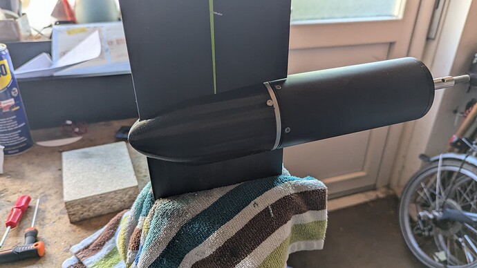
We did a “test” fit, and the motor mount feels completely solid, however, we are not happy with how the nose cone is fitted.
We are now going to make two small brackets to see if this fixes the problem. If not, we have a few other options too.
This it what I meaned, it sits inside the mast. Still got the option to screw it if necessary. @Kian thank you for the pictures. And now your cone is shortened, perfect work. ![]() @Kian why are you not happy with the cone?
@Kian why are you not happy with the cone?
The cone is fine; however, the four small (M2) screws at the back of the cone that hold it in place are very close to the edge.
Since it’s 3D printed (PETG), it will definitely break. We might try a nylon cone to see if it’s any better.
Originally, my dad designed the mount with “walls” on both sides, pointing forward with the M3 holes in them, but he had to remove them because the CNC tool couldn’t reach the back of the mount. (I guess my dad was in 3D printing mode when he designed it!)
