I’m curious if it is a remote issue or a VESC issue ? Seems like duty cycle could be good way… if it worked. Maybe something could be fixed on the VESC side.
I have not tested PPM mode and that’s not an option because you will loose the telemetri of the few values you have (battery, amps, temp and watt). On the other hand, I’m quite sure that the number of readings from the trigger would still be the same. My guess is that either the VX3 processor can’t handle more than 8 bit analog read (0 - 255) or that their readings are to noisy and therefore decided to stick with 8 bit.
There is no option for duty cycle, it’s PPM for non VESC mode and current for VESC mode.
@JamieJiang, any comments on the trigger issue or reception issue? Is it possible to update the firmware on the remote and/or receiver?
What is the difference between FSESC versus VESC mode?
Was a funny Situation, I helped a friend to configure the VESC.
When we tested it after, we got not all Data on the Display ( VESC mode ).
After we switched to the FSESC mode, we got all Data.
His VESC is an HGL Tech 75/200.
Has anyone had any success with the Vx3 with an ESC vs VESC? I’ve got the HIFEI Technology Co., Ltd. SwordfishX 300 A ESC and the Vx3 on the way for my first build. Hoping these two will play nice together. Website claims VX3 works with ESC … but from posts it looks like I’ll be, at minimum, soldering on a couple new wires to make it work.
Just received and tested my Vx3 by wiring it to a servo to test the PPM output (no ESC yet - still early in my build) I’m new to this so I could be out to lunch, but the servo is only moving about 30% of the range it should be for the standard 1 -2 ms pulse width. I’ve also heard others having similar issue with the remote only getting them tp 30% power on ESC’s. I did calibrate it, and I ensure it was in H gear. Not sure what more can be done. Ideas?
Update - looks like a buddy of mine got it working with his ESC by calilbrating the ESC itself to accommodate for the non-standard pulse width coming out of the Vx3 remote receiver.
1 Like
mlab, that sounds great. Can you translate a little and describe how your friend did this? Thanks!
OK here’s what I think I know: Normally the signal used to control speed output of an ESC is a input pulse with pulse widht between 1ms and 2 ms. i.e. 1 ms means motor stopped and 2 ms means full speed. 1.5 would be 50% power. So, as I don’t own an oscilloscope to measure pulse width, in order for me to see if the flipsky receiver was outputting the standard signal on its PPM wire I connected in to a servo ( RC type plane) since I know it uses the standard input where 1 ms = 0 degrees and 2 ms = 180 degrees. The servo was only moving about 30% so I guessed there would be an issue with connecting it to my ESC. My friend had experience this with his full setup as well until he calibrated his ESC. Thing is, an ESC need to be calibrated to adjust for different receivers (i.e. different ranges of pulse widths). Each ESC is a bit different is how this is done (check the manual for yours) but it normally involves powering it on while holding the remote at full throttle then releasing throttle completely to “teach” the ESC the range of the remote.
3 Likes
Thank you. Still learning here. Now I know a little more. Appreciate your response.
I am surprised they are only using 30% of the possible PWM range. This explains why the throttle resolution is so bad. Unacceptable on a $165 controller.
40 steps for throttle??? 2,4ghz? That’s all not ideal for efoiling. I thought this remote would crush mine, but turns our otherwise. I’m 1 month away from mass production. My trigger has 500 individual steps and a precision form 1. So if you hold full throttle then release it you have ±1 value, which is extremely accurate. Plus I am working with 433mhz which easily panatrates carbon water and everything in-between. Next my display is bigger displays all relevant values. You can limit amps wattage. Set you minimal voltage. Get notification when under 20/10/5% battery remaining. Wh counter cruise controle based on gps and normal throttle, logging updating Ota And much much more. Plus my remote will be in the same price region, if the demand is there.
I really hope to bring something great to you guys.
Felix
11 Likes
I am having the same antenna connection issues. Swapped out the Maytech for the VX3 and connected the same antenna used on the Maytech to the VX3 receiver board and as soon as I’m in the water it cuts out on me. So it’s definitely relying on it’s internal antenna as my external antenna goes all the way to the nose of my board and that is not covered by water. I did multiple tests but as soon as my enclosure area is submerged it cuts out on me. Help!
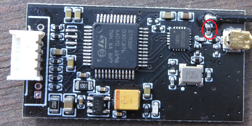
After desoldering the 0R resistor to the internal antenna, the connection gets more stable. I believe we are back to the same reception as the Maytech setup.
While I’m at it, I’ve done a few more modifications as well.
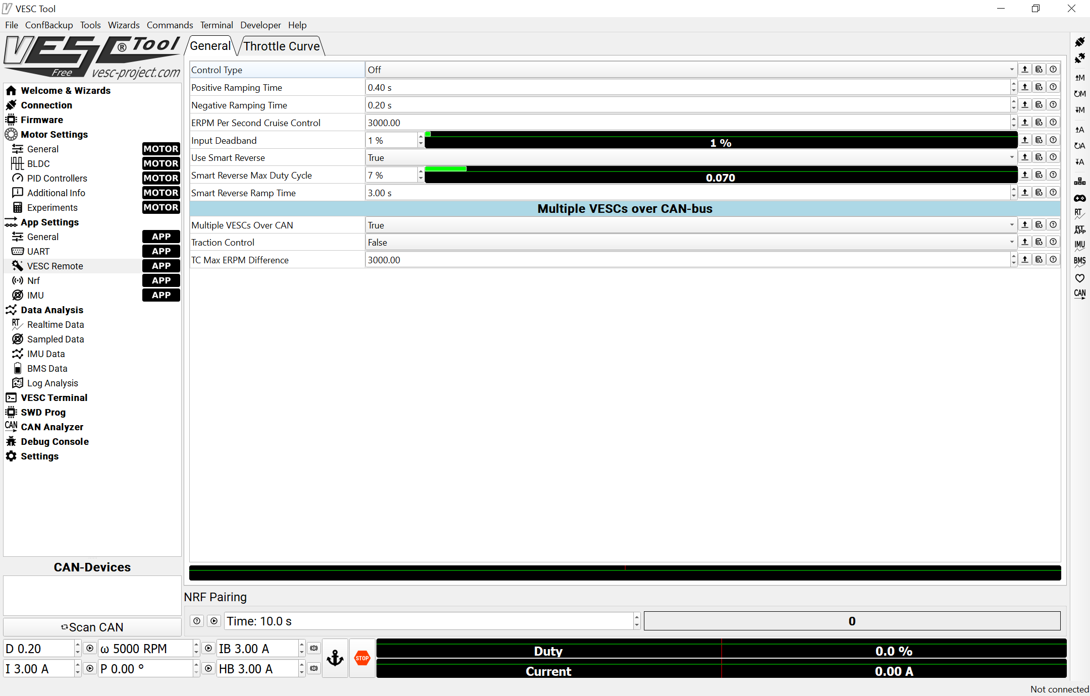
In the VESC tool, set the dead band to 1% and tweek the throttle curve to become a bit flatter around your ‘sweet-spot speed’. This will at least give you a bit better trigger resolution at the speed you are usually running at. It’s far from perfect but the sudden positive and negative accelerations will get smaller.
Edit:
I found the place where I’ve heard about having parallell antennas not being a good idea (around 11:05 in the video).

Can you give me a little more information on the desoldering of the 0R resistor? Did you do that in that picture as it doesn’t look like it? I am quite afraid to do anything like that. I can’t believe Flipsky didn’t see this as a potential problem. I too have heard multiple antennas is a horrible idea. Maytech receiver at least doesn’t have the internal antenna which is likely why that one just worked once an external antenna was connected.
The picture is the previous post is before desoldering the resistor and here is one after
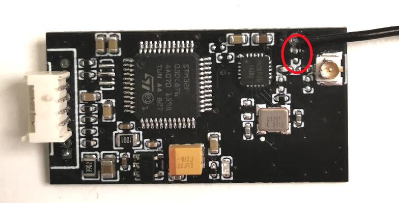
There is nothing to be afraid of, it’s easy to undo the removal of the resistor by shorting the two pads again with some extra solder.
Totally agree, how is it possible not to have seen this problem.
Good luck
The desoldering of the resistor did not help me. I did that, hooked up the external antenna and then placed the board (mine is a Lift board) so that the entire enclosure was under the water but the nose of the board (where the antenna stops) is above the water line. I was still getting signal cut outs. Maybe not as bad as yesterday with the resistor in place, but enough to make me very hesitant to use this remote+receiver.
Any other ideas? I am using FSESC to connect to my Flipsky VESC so it gives me battery remaining. On the Maytech I was using PPM. Does that matter?
Sorry to hear it didn’t help. I’m out of ideas. And, as I said before, this is not the only problem. The trigger resolution is just as bad. It’s a shame, with just a little more R&D, this could have been a good product but it stumbled on the finish line.
I had a session yesterday too, and I’m seriously considering swapping back to the Maytech setup due to the trigger and rather wait for @Mantafoils or @Felixfoiler to finish their product and hope they have addressed the problems encountered so far.
Also, I’m not that far from having a prototype of my own version ready.
2 Likes
@JamieJiang We can all see you have been reading 2h recently so you cannot have missed our problems. Can you please respond to them
From Flipsky Aliexpress seller : “hello friend,We have read the information, there are some problems in the use of the customer’s remote, and our project is also analyzing the reasons for this situation.
We have sold a lot of VX3. At present, We have not received any negative feedback on Aliexpress. We will try our best to do a good job in quality control.
And you can contact me if any questions about the usage.”