Build on a Weekend

Since I have already received questions about the battery from various people, I am creating this new topic here. @th3v3rn
I know it’s nothing new, but maybe it will help someone.
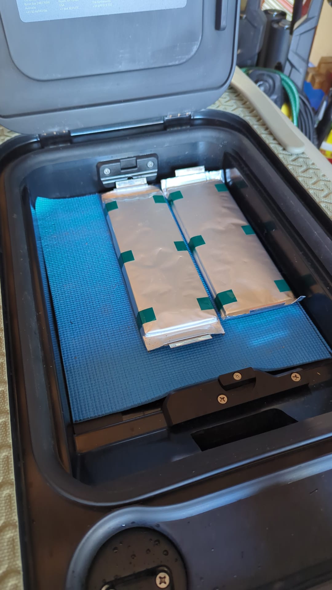
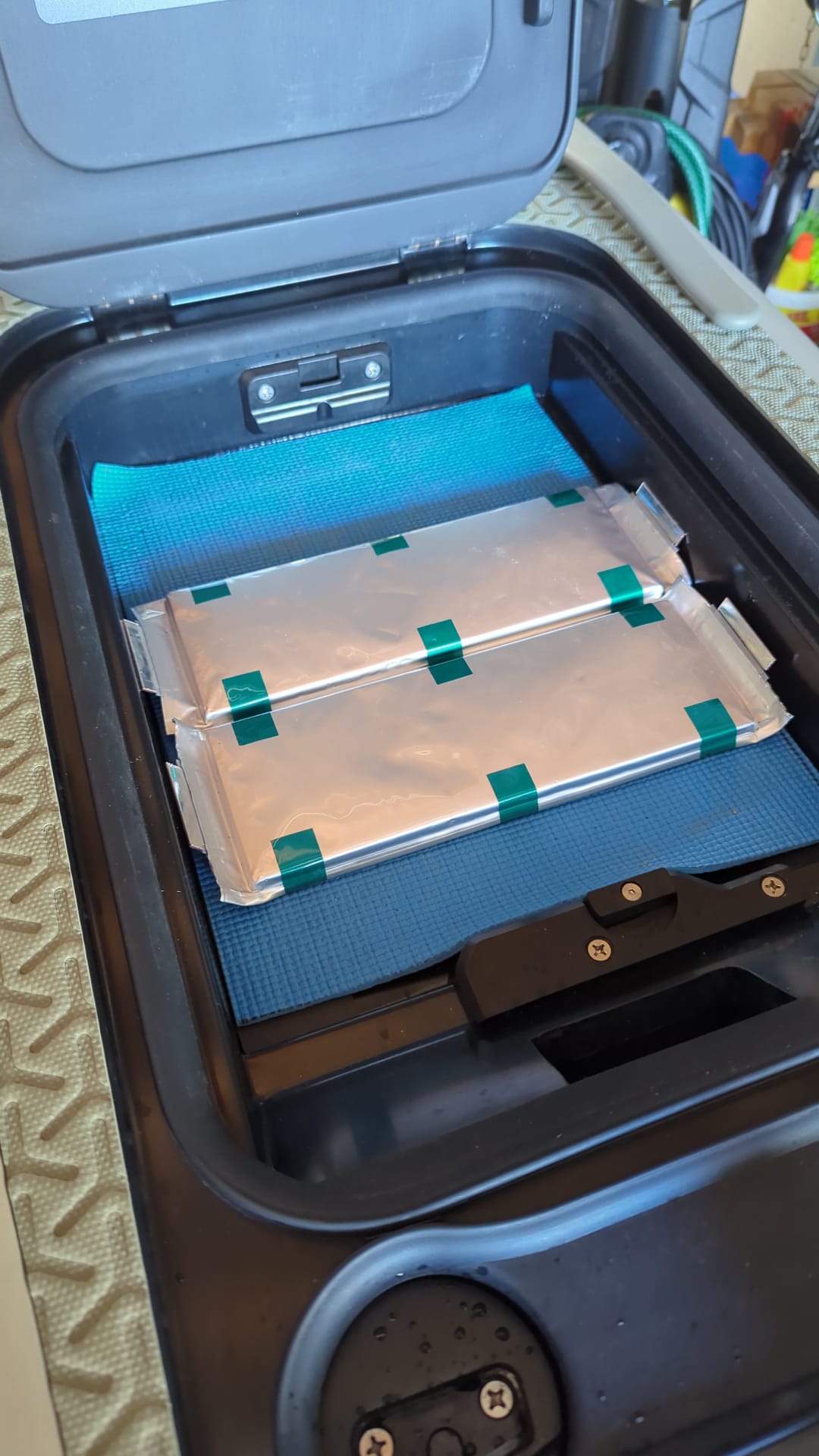
The battery compartment of the Fliteboard 1/2/3 is 390mm long, 305mm wide and 80mm high. It is important that it is not higher so that the hatch still closes.
Furthermore, the two corner radii must be taken into account.

At Ali you can get these beautiful ABS housings in 29x19x8cm for 30€ including cell holder and nickel-plated steel.
https://de.aliexpress.com/item/33017871879.html
These are ideal for small 1KW/h packs, for a reduced flywheel mass (like Flitecell Nano).
Two of the packs fit in the compartment but I really wanted to use 21700 cells. So I thought about how to build a simple and cheap case and came up with the following solution.


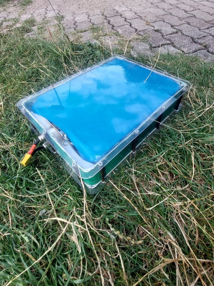
We all know how impact-resistant and indestructible polycarbonate is, at the latest after watching various YouTube videos (Hacksmith). It is also extremely cheap and very easy to work with.
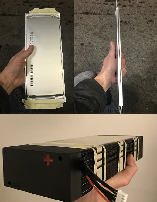
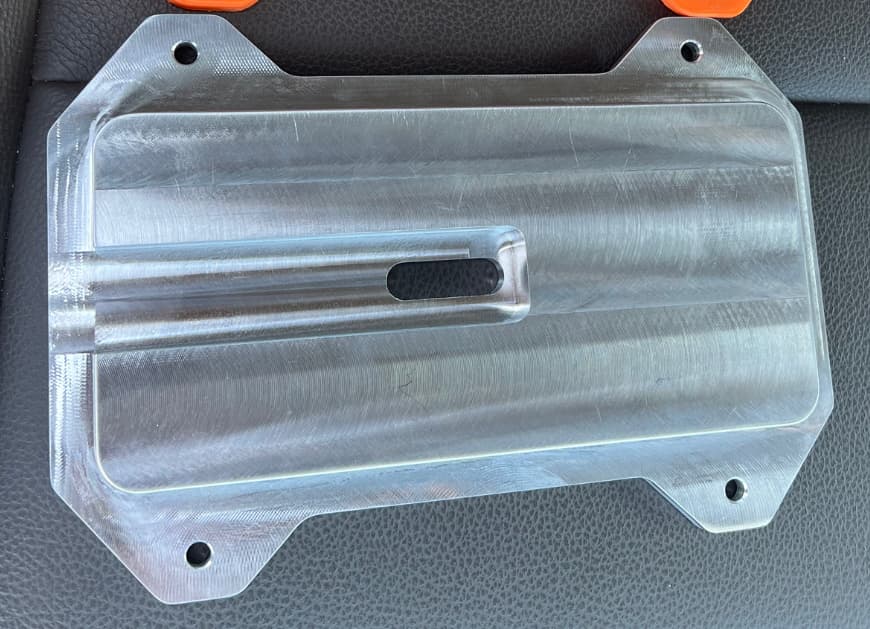
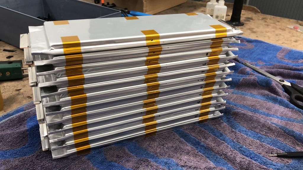
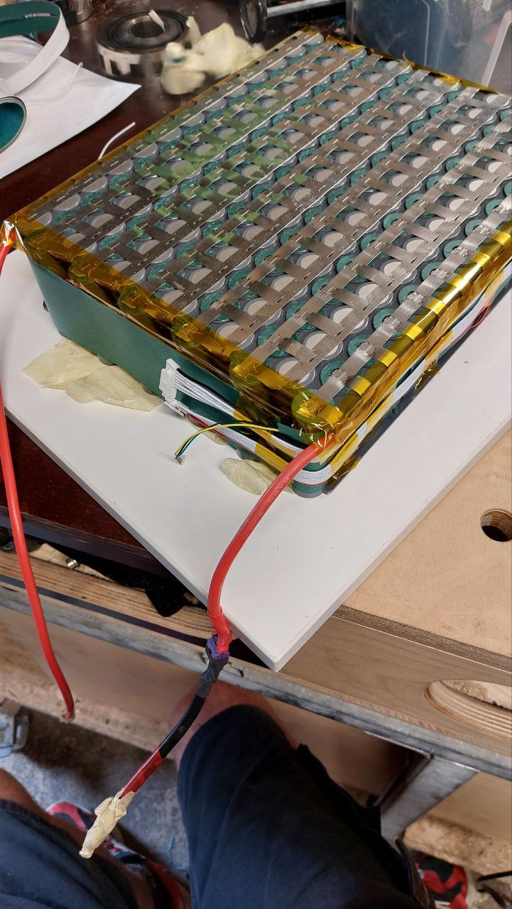
When I looked in my warehouse, I saw a beautiful piece of aluminium dibond. It would certainly also work well and dissipate the heat well, but it was planned for another project and the prototype had already been milled. The 21700 cells were packed with 0.2mm nickel strips, Kapton tape, fishpaper and heat shrink tubing, bringing them to 71.5mm. So there is still 8mm left for the lid and the bottom.

After a short calculation and a test I came to the conclusion that 3mm polycarbonate is sufficient.
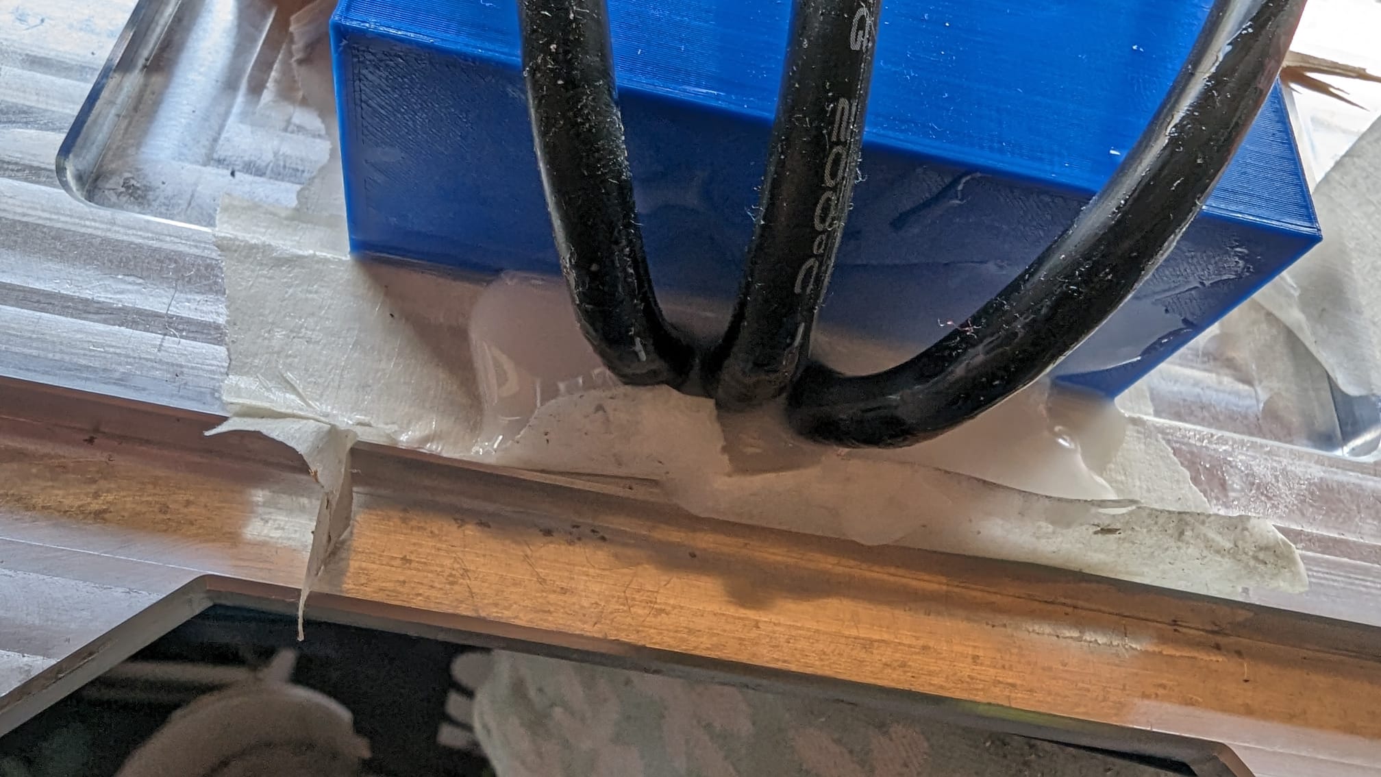
I milled 1mm grooves in the two panels with the CNC and inserted a 1mm side panel. It can also be done with a normal router, the groove doesn’t have to be very professional as it is very flexible.
It is held together by brass sleeves with M4 threads. I had these lying around and they were cut to the right length on the lathe. If someone wants to rebuild it, just look for threaded sleeves or connecting sleeves, they are usually easier and simpler to get.
The side wall was simply glued with Sikaflex.
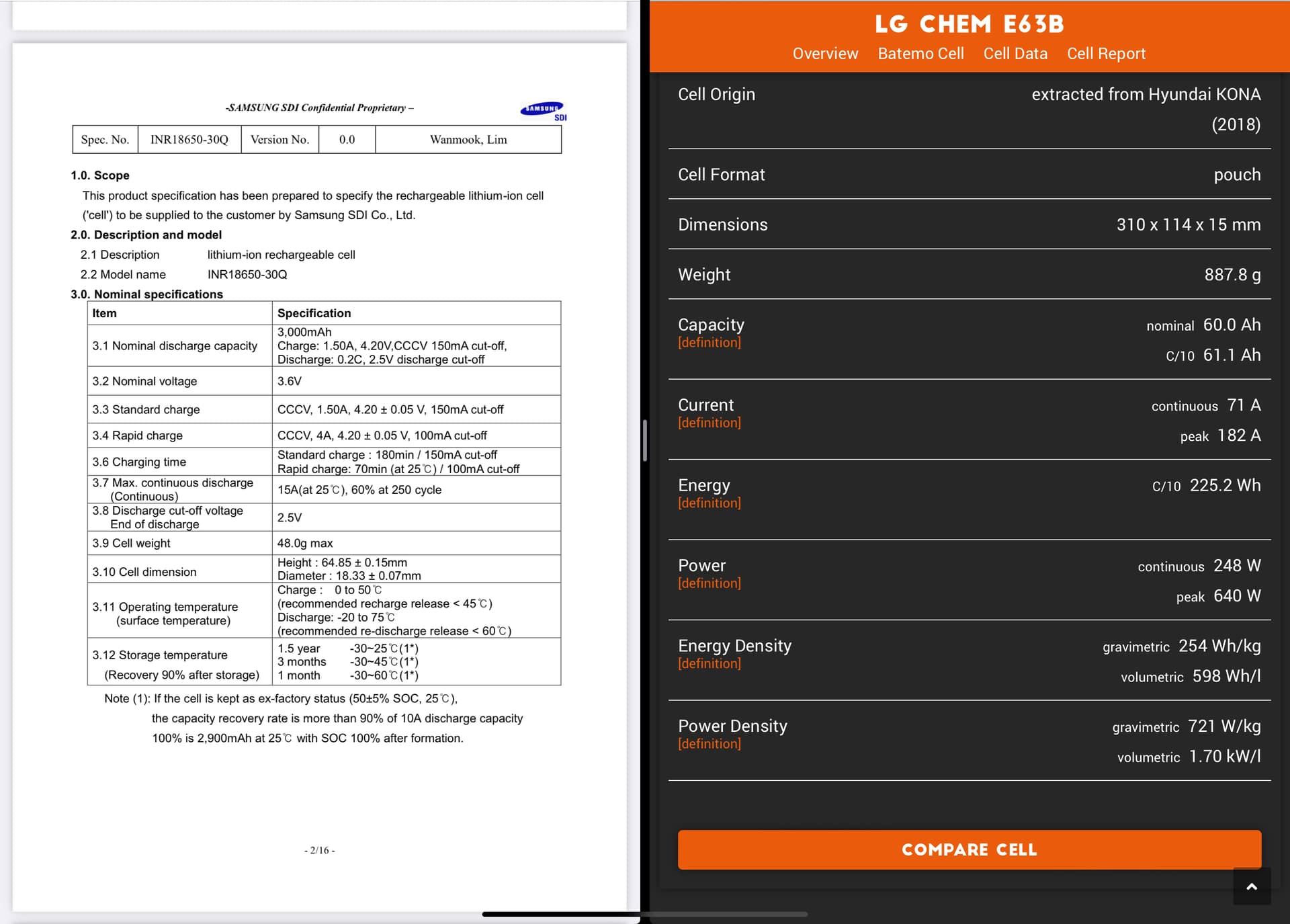
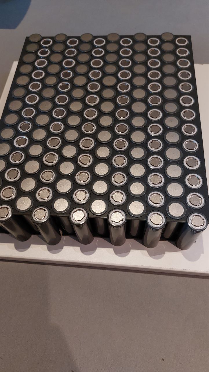
I chose LG M50LT cells because they are good value for money and deliver enough current.
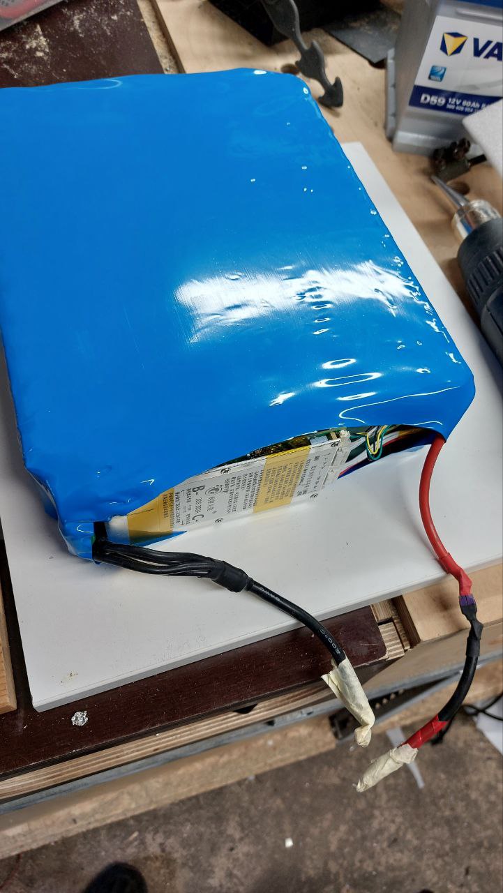
Since I want to use the battery in all my boards, it is a little smaller 37x28x7.8cm. It is 12s13p, i.e. 2.85kwh, so I should not have any range problems.

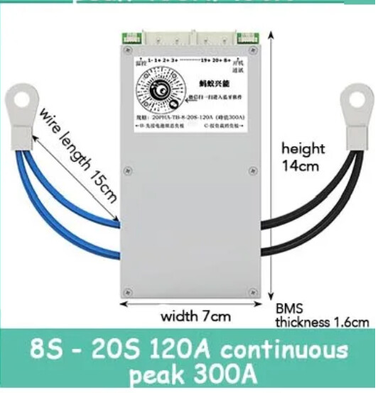
The special thing is that the housing is very robust, can be built in 30 minutes, is cheap and you don’t have to laminate a box. Yes, it is modelled on the Flitecell explore, but with a weight of less than 1 kg it is not particularly heavy. The total weight of the battery is 12.4kg, which I consider quite acceptable. A maximum of 14s14p with BMS or 14s15p will fit.
Then you would have 3.5kwh at 15kg weight.


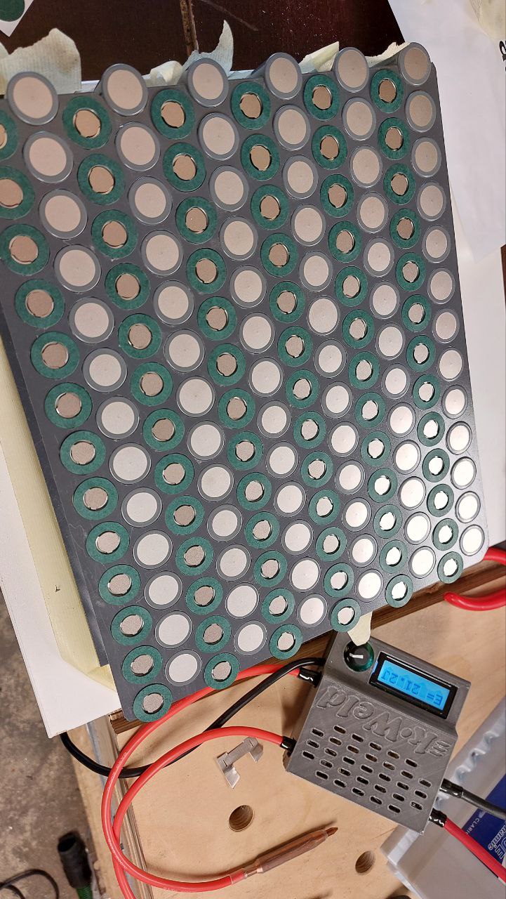
To save time, I also quickly milled the cell holders from 1mm instead of printing them.
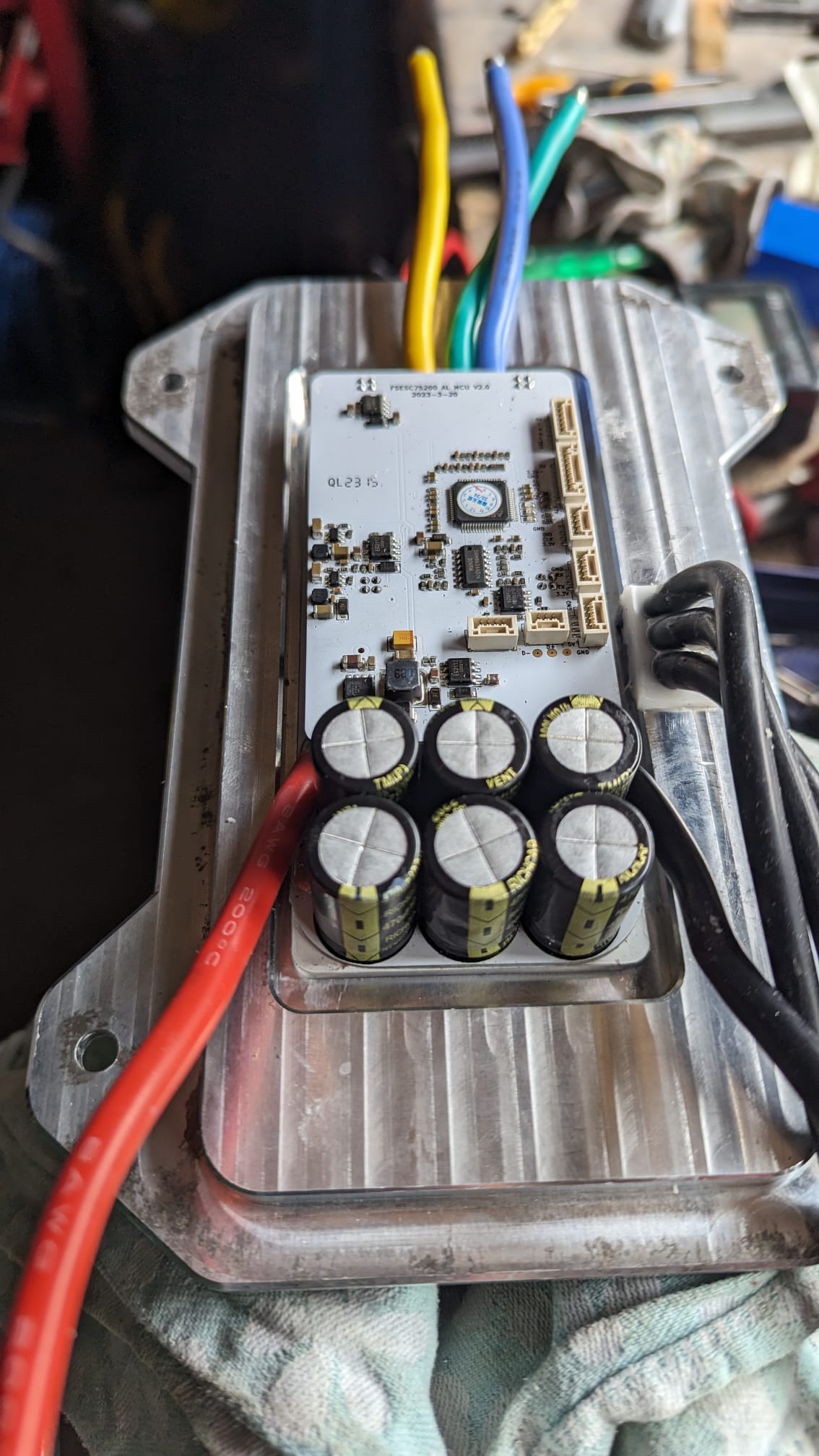
The busbar and the balencer connections are simply folded to the side, as is usual, so as not to lose any height. A 200A mini ANL fuse is also installed for safety.


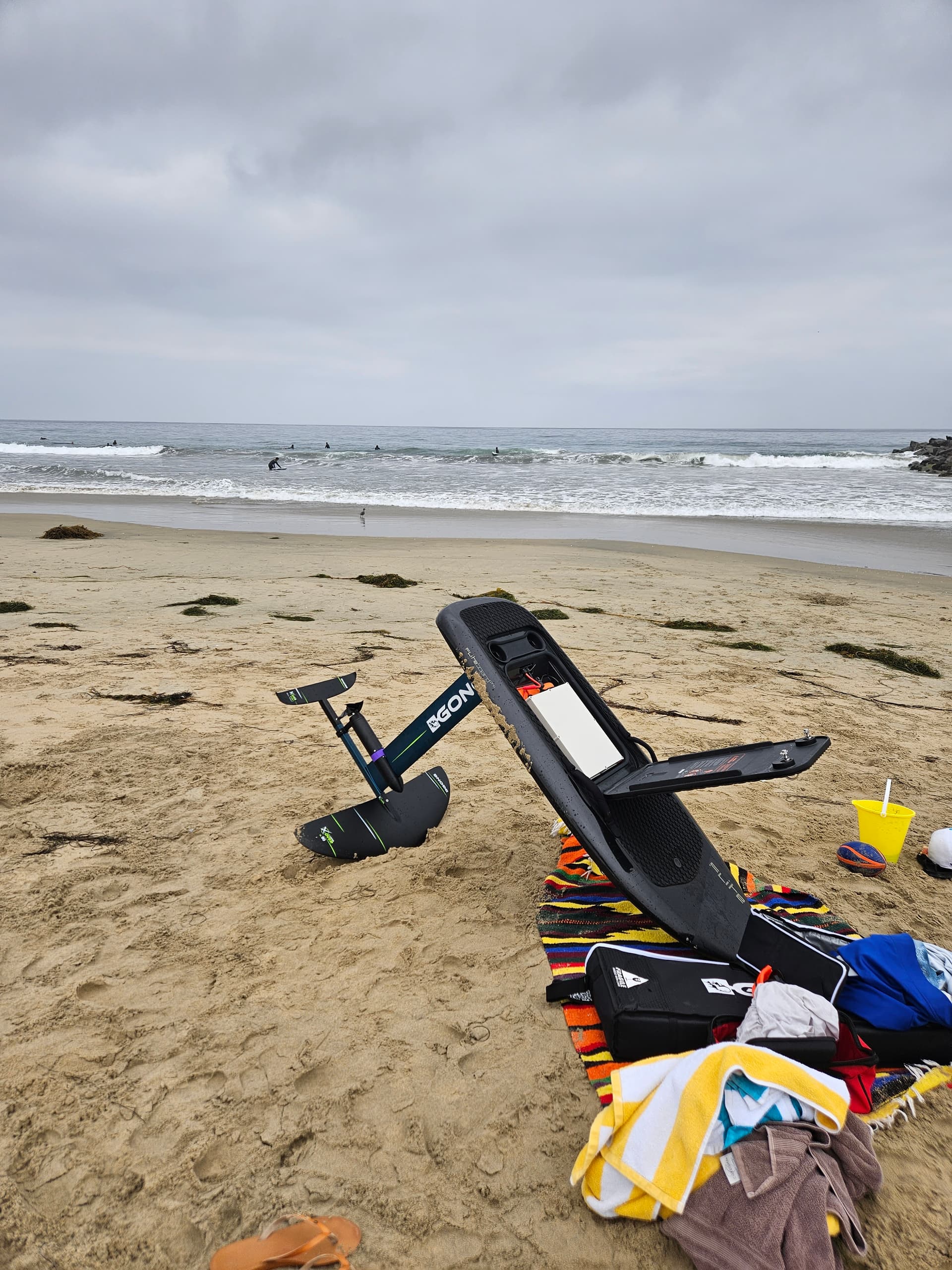
The pack has now been used as a foil, jetsurfstyle and etow at 4600W continuous power. The cells have only warmed up by 3 degrees. So all is well. Smaller packs with 8p should therefore also not be a problem.

7 Likes

Nice build!

Would be nice if the battery “lock” system could be used to keep the battery in place.

My next battery pack for the Fliteboard will be made out of lg chem e36b pouches.

Also. Did you notice that the box is a little bit tapered?

~Kian

1 Like

I’m anything but a battery wizard so tried to compare a popular 18650 cell with the pouch you have chosen.

Looks like this

So roughly 20 cells = 1 pouch capacity
Pouch is lighter than 20 cells

What are your other variables in going with pouch as it’s the first design here that I’ve heard of using them?/

You think a 14s14p battery would fit with BMS? Any pics of the battery in the bay? Do you have a step file for the cell holders? That is slick.

At least 2 projects I remember of did use pouches.

1 Like

Thanks I found one of them

2018 KIA SOUL battery pouches, by @Riwi, NMC technology not Li-Ion
'Search results for 'KIA SOUL' - FOIL.zone

'The other way around - #21 by Riwi

The pack: 6s 42,5ah. 5kg. Size 360x130x65mm, 6 x 4.2 = 25.2V per pack, 2 pack in series = 50.4V
'26650 batterypack - #6 by Riwi

The tests:
'DIY lid for the electronics - #37 by Riwi

EV pouches are great in every way when you can get them, i’ve been running these since some years and the output is great, my variations have been from LG 25Ah pouch in Volvo V60 hybrid pack to Samsung SDI 37Ah from VW, plan on building a pack with LG E78 pouches soon. The power available will never be needed on an efoil though, these cells can output 2-300A easily.

Beware of recalled cells, there have been a number of issues with cells lately and the market seems flooded with warranty replacement cells being sold as good ones. This is the downside, if you buy cylindricals you can easily get genuine, new cells but for pouches there aren’t many options for new, off-the-shelf genuine cells.

2 Likes

@vincent
I now have my Fliteboard conversion operational and am really enjoying it!!

I have decided to build another battery pack and am seriously considering using the same cells that you have in your build.

Thanks for all the dimensional info and the case design is a great solution imho.

Can you share what BMS you are using and why you chose a 12S13P configuration?

I’m also interested in if you are using the BMS just for charging?

I’m glad you’re having so much fun and everything is working. The cells are great and have a good price-performance ratio. However, the battery pack must be large enough, as the current output is somewhat low (at least 8p). I chose this big one as it is the biggest possible that fits in all my boards. Since an ESC only supports 12S, I decided against 14S. If you have the option I would definitely go for 14S(more performance, less power). The battery size is a compromise between range and weight. 2kw/h is usually quite sufficient. I have an ANT smart Bms with 300A peak. I use that for charging and discharging. It is ideal because of the 70mm height.
https://a.aliexpress.com/_Eyng2OX
A small charge only is also sufficient. An external model charger usually has a much larger balance current. The Junsi X12 or ISDT X16 are both good devices. Or split the pack into 6s or 7s. The chargers are cheaper there. At the moment I use the R4850 or R4830, R4870. In my opinion, the best charger for our purposes. Adjustable voltage 6-14S and adjustable current. Everything via CAN or Wlan/Bluetooth. 3000W, small, compact 97% efficiency and cheap at 100€. It is really a very good quality, and better than the classic small HP server power supplies. More on this will follow shortly upon request. Very widespread in the DIY PV sector. I am surprised that no one uses it here yet.

1 Like

Vincent

Thanks for the info !

I assume this is the model you are referring to?

I’m also interested in further detail or links to the charger you mention.

I currently have a 12S12P config of 18650 Samsung 30Q cells and I’m getting roughly 1hr - 20km of ride which for me right now is plenty. :slight_smile:

So optimal that’s 36,000mah or approx a 7P of the 21700 cells so I think I understand where your 8P minimum comes from. Perhaps this isn’t as linear as this but I’m thinking 10P of the 2170 cells anyway. Haven’t really decided on that yet. Might make a big “explore” pack and a lighter “session” pack similar to what I have now.

Is your case stiff/sturdy enough to allow it to be removed from the board without flexing? I’m careful handling things but I have a family member who is NOT so want to make sure it will stand up to some abuse.

I assume you made the case fit the full cavity in the board and put some type of spacer inside the case to fit the battery’s or did you design the case around the cell layout with no slack and then use spacers inside the cavity of the board?

I also am comfortable at 12S as that seems to work well on my setup and is somewhat safer than 14S if I understand correctly.

Can you explain a bit more about how the 6s packs would work. Ie two bms and then a plugable wire harness to put them in series?

Sorry if these ? are simple but trying to learn on the fly :slight_smile:

So I water tested for the first time and blew the ESC. I used the abs housing and used Sikaflex to glue and also bolted it down with tapped holes. I also siliconed the ever living god out of the motor cables coming through the adapter plate.

I think water came through the cables still TBH. What are you all doing for waterproofing? Is dousing in epoxy a bad idea for heat if I am also using thermal paste between the VESC and mast plate?

Also was only getting 40amps so couldn’t get on plane. Need to figure that out with the new ESC.

I used the Permatex sealant I referenced above. Messy but seems to work well.

I sealed the hole in the side of mast where the motor wires enter and then sealed the top of the mast where the wires exited. The bottom of the Gong V2 mast has rubber seals between the wire hole and fuselage connection already so I’m quite confident the inside of the mast remains dry.

Let that set up as its messy and I didn’t want to wiggle the wires around much to keep the seal. I think this point is very important to allow the sealant to “fix” itself to the motor wires.

Installed mastbase and sealed that hole and let it set again.

My adapter plate is a bit different, thicker and different hole placement. See photo before I through drilled and tapped for the connector bolts, so my wire hole is directly above the hole in the mast forming a deep chimney for sealant.

Things got really messy from here on as I had to put the thermal paste on and not get it where more sealant was needed. Lots of paper towels, qtips etc but managed to get more sealant in the wire hole and on the threads of the holes and bolts. Get it all together then let it set for at least a day. The sealant is designed for high temp motor gaskets so thicker layers take a lot longer than it’s design spec.

The bolts were short enough that I could put more sealant in the holes from the top side of the plate.

Clean the plate and the bottom of vesc and apply thermal paste and bolt the vesc to the plate.

I have not made a cover to go over the 75200 vesc. I managed to get the whole thing inside the board and secure it with the 4 Flite bolts through the ears of the adapter plate - of course with the orange Flite seal in place. I will figure out a 3D cover for the wire “glob” on the vesc this winter when I can’t foil! :grinning:
I do not need to remove the adapter plate from the board to transport, just take fuselage off and it fits in my van.

I have had multiple 1hr sessions and the vesc temp has not gone above 31C and not a hint of water inside.

I am so glad to be rid of water cooling through the vesc as it was always prone to a big leak and bad things happening!! NEVER AGAIN!

Lots of aluminum heat sink via vesc, plate, base and mast

Hope this helps!! Great rig once you get it sorted!!

1 Like

We used Permatex sealant too. We even used an old syringe to “inject” the sealant.

We also used some sandpaper to roughen the silicone from the 3 wires at the place it’s touching the sealant.

It’s all verry messy, but 100% waterproof.

1 Like

The syringe is a great idea!!

The “nozzle” that comes with the tube helps but still hard to control quantity that comes out.

How goes the battery build?

1 Like

Not started with the new battery build. It will be a winter project.
Looks like we can only get 12 pouches in the box. 13 “might” fix, but no room left for a BMS.

1 Like

Is that a width of the box or length restraint?

For this cell it’s the length as the tabs should not be bend (the cells in the pictures are dead)
3 piles of 4 in a stack.

Length layout:

Width layout:

1 Like

Interesting - thanks for the photos.

Ive done a little reading and some packs were known to expand some during use. Perhaps that was early versions and is sorted now.

Will you use a separator between layers of the stacks and vertically so each cell has a “pocket”?

Not my picture, but they will be stacked without a separator between layers.

1 Like