I’m also interested in the concept of welding the mast directly to the adapter plate.
Can you share more detail on your plan?
I’m also interested in the concept of welding the mast directly to the adapter plate.
Can you share more detail on your plan?
The overall plan is to machine a similar motor adapter plate as you have seen here, about 1.5mm smaller in radius than the motor to accommodate for the nose cone. Then machine off about 10-20mm from the trailing edge of the mast. This allows us to weld into thicker material, since the trailing edge is very thin. After initial tig spot welds, add some ribs as well to strengthen the mount. Finally print and install a suitable nose cone. I’ll probably do this upgrade during next winter.
Thanks for that info, that’s interesting as well. What I was considering was welding the actual mast to the board adapter plate - eliminating the mast base that would be used in a more traditional build.
I have a mast with a Tuttle head that I was considering repurposing for this project. I bought it for foiling on a windsurfer but don’t use it anymore. The Tuttle “head” is quite robust compared to the actual mast extrusion so once cut off square might be OK welded on to the thick plate of the Fliteboard adapter so I am looking for opinions of whether that is a valid idea.
I don’t have the tools or metal working experience to do this so would have to job out the fabricating and don’t want to waste $ if this is a dumb idea.
I have been thinking through some finer points of my potential build ( I might have found a good used board!) and was wondering about the maintenance aspect of sealing the motor wires in the mastplate.
I’m wondering which sealant would work best. First priority is quality seal of course so wouldn’t want to compromise that but it would be nice to be able to get the wires out if/when I had to. I’ve only worked with silicone but am wondering if your other two product selections would be better.
I also am considering having bolts or studs in the adapter plate rather than threaded holes. Tightening would be using a nut to attach the mastplate which I think I could torque easier than screws but maybe Allen head screws do just as good a job.
Studs would be nice, but you will need to intergrade them with the plate!
Counter sinking them from the inside could work, but might leak?
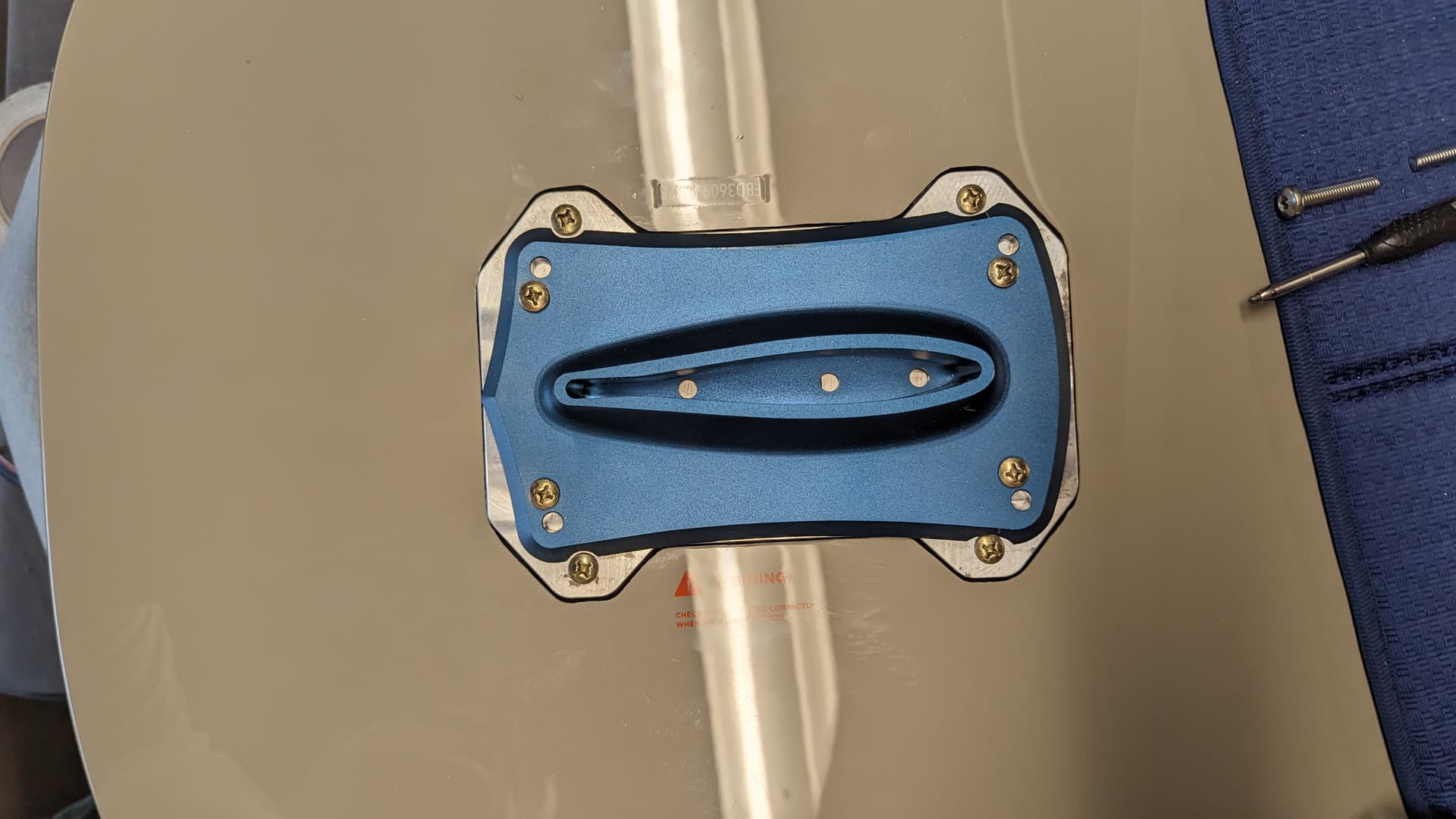
The original holes from the Gong mast plate align directly with the “wall” of the box inside the board.
The plate (we used) is at the original Gong holes only 5mm, so not enough for tabbing threads.
We have opted for this way (see picture). Plate thickness at that point is 10mm.
It is not pretty, and when we took the picture it was a testing setup. (We are now using allen screws all the way around.)
I do not remember the name of the sealant, but it’s tough as hell.
We 1st needed to add a primer, and needed to roughen the 3 motor wires up with some sandpaper.
When we get back home again I can look up the name of the sealant if still needed.
Thanks
I’m likely overthinking the bolt thing and I share the concern of through bolt leaking. I would like to keep potential leak points to a minimum and why reinvent the wheel. Already proven approach by @vincent and others. Thanks for the perspective!
I have recently used this product to fix a leak in my battery box. Recommended by a friend and although messy - really sticky toothpaste consistency it sets in 90 minutes and seems very durable and heat resistant.
I’m convinced that following your lead on using screws to attach adapter plate to mastplate is the right approach.
I looked in the thread for screw sizing so I could find a source of them and all I found was the A4 70 comment. I didn’t know what that was so Google to my rescue. 
What I don’t know is the diameter and length required for the plate designed for Kian.
My new mast plate will be one piece. But with the adapter plate option, the threads are sufficient. There is a so-called minimum screw-in depth, which depends on the screw and the material. For the aluminium I use, it is 6.4mm. You can also strengthen the connection with screw glue such as Locktide. In addition, the thread is not constantly screwed.
The board has now been through 3 loading cycles with a 145kg load (two people) in 35cm waves, as well as jumps. Seems to hold up well
You need M6 16mm A4/2 70.
Normal tin-plated screws would also work for testing.
Thanks for being patient with me. I have tendency to get locked into the detail of things.
Great info on screw type and application. Do you have video of the two people riding a single foil??? That would be fun to see!
You mentioned in your build thread that the second iteration would be adapter plate and mastplate all in one. Is that something you have developed and are willing to share? My mast choice at this point is the Gong aluminum V2 85cm. I can see the value of a single unit.
It’s difficult enough as it is, I haven’t managed to hold a camera.
I still have a lot of 30mm 7075 lying around. On my CNC I only have cutters with a maximum cutting length of 45mm. For the mast cut-out I need 3mm and there I am limited to 27mm.
Hence the plan to countersink the mast flush into the plate. So not like the original version. This saves me a lot of milling time and I have less resistance, which doesn’t matter.
I’m just worried that the planned 25mm of the mast won’t be enough. Is there anyone here who can help me with this? Instead of the CNC I had also considered using my Phantorouter, as this is even more precise than the drawing on the PC.
The weight is about 900g, so you also save a little.
I can’t imagine how challenging it is for two people to coordinate balance to foil on one board. Cirque du Soleil stuff ! ![]() Lots of drone photographers would be happy to capture that action, I know I would.
Lots of drone photographers would be happy to capture that action, I know I would.
I don’t have metal working experience or tooling required to assist you or I would ![]()
My plan is to have a local fabricator produce the adapter plate. The step file you produced for Kian will work with the Gong mastplate I can get.
Due to my lack of experience I don’t completely follow your concerns with fabricating the all in one adapter and it seems that you are still mulling over how best to produce that. I’m sure you will work out a great solution and hopefully share it here at some point.
Thanks again for all the support you provide!
I didn’t realize that there is a requirement to drill new holes in the Gong V2 mast base to fix it to the adapter plate. It didn’t sink in even though I saw your photo. I did some quick 3D prints of the various parts and when the mast base holes didn’t line up with the ones in the adapter plate I realized I had missed something.
This is of course is driven by the thicker part of the adapter plate where the drill and tap holes need to be being narrower than the full width of the plate. The standard width spacing of a mast base would have the holes in the thinner area.
Not a big deal overall strength wise I hope but moves away from the original Gong design in that perspective.
I managed to find a used 100l Flite board and have ordered new Gong rig so hope to have it together and out on the water soon.
Since I have already received questions about the battery from various people, I am creating this new topic here. @th3v3rn
I know it’s nothing new, but maybe it will help someone.
The battery compartment of the Fliteboard 1/2/3 is 390mm long, 305mm wide and 80mm high. It is important that it is not higher so that the hatch still closes.
Furthermore, the two corner radii must be taken into account.
At Ali you can get these beautiful ABS housings in 29x19x8cm for 30€ including cell holder and nickel-plated steel.
https://de.aliexpress.com/item/33017871879.html
These are ideal for small 1KW/h packs, for a reduced flywheel mass (like Flitecell Nano).
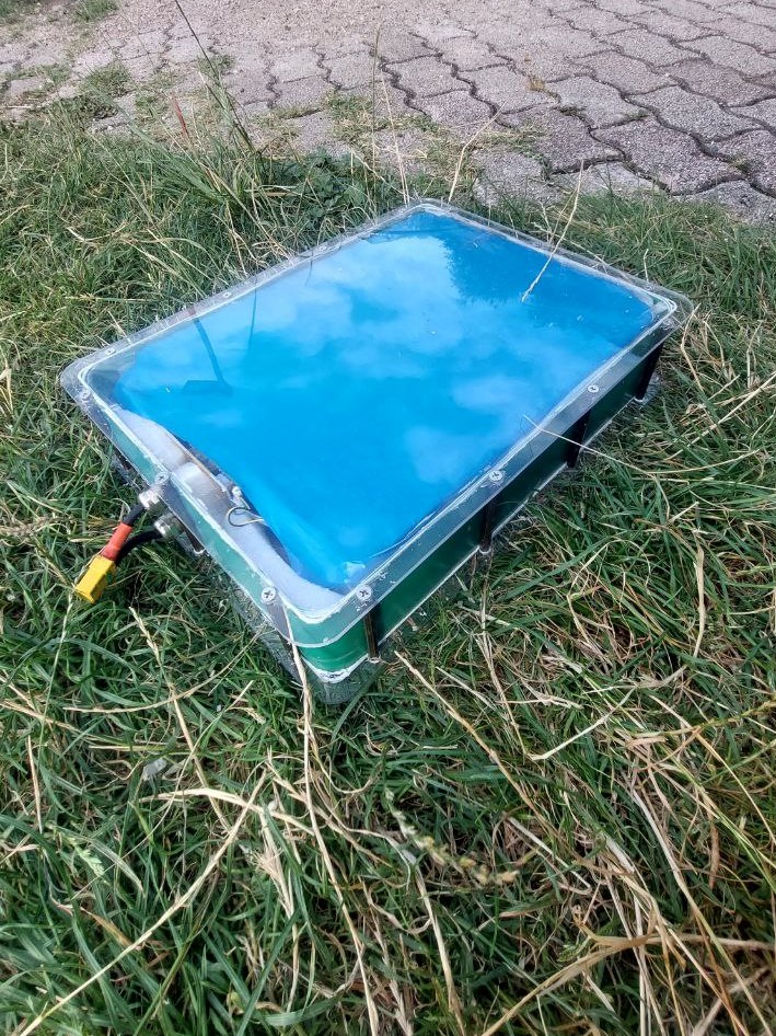
Two of the packs fit in the compartment but I really wanted to use 21700 cells. So I thought about how to build a simple and cheap case and came up with the following solution.
We all know how impact-resistant and indestructible polycarbonate is, at the latest after watching various YouTube videos (Hacksmith). It is also extremely cheap and very easy to work with.
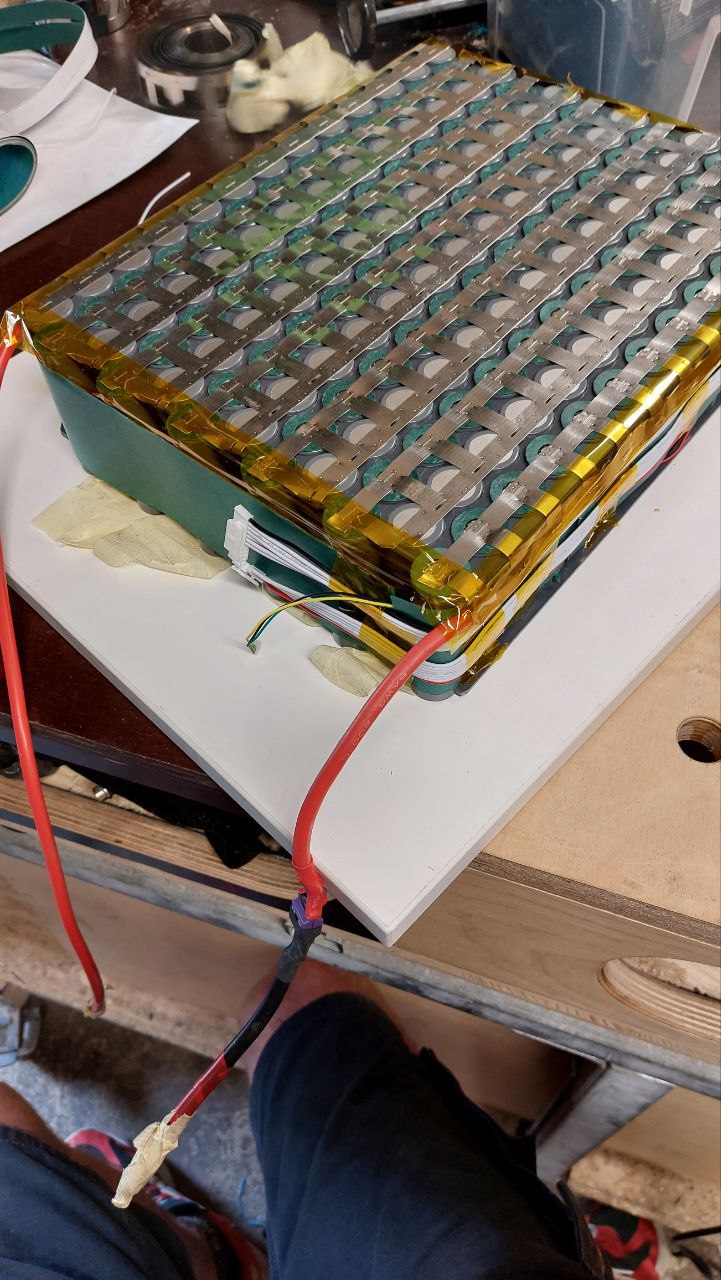
When I looked in my warehouse, I saw a beautiful piece of aluminium dibond. It would certainly also work well and dissipate the heat well, but it was planned for another project and the prototype had already been milled. The 21700 cells were packed with 0.2mm nickel strips, Kapton tape, fishpaper and heat shrink tubing, bringing them to 71.5mm. So there is still 8mm left for the lid and the bottom.
After a short calculation and a test I came to the conclusion that 3mm polycarbonate is sufficient.
I milled 1mm grooves in the two panels with the CNC and inserted a 1mm side panel. It can also be done with a normal router, the groove doesn’t have to be very professional as it is very flexible.
It is held together by brass sleeves with M4 threads. I had these lying around and they were cut to the right length on the lathe. If someone wants to rebuild it, just look for threaded sleeves or connecting sleeves, they are usually easier and simpler to get.
The side wall was simply glued with Sikaflex.
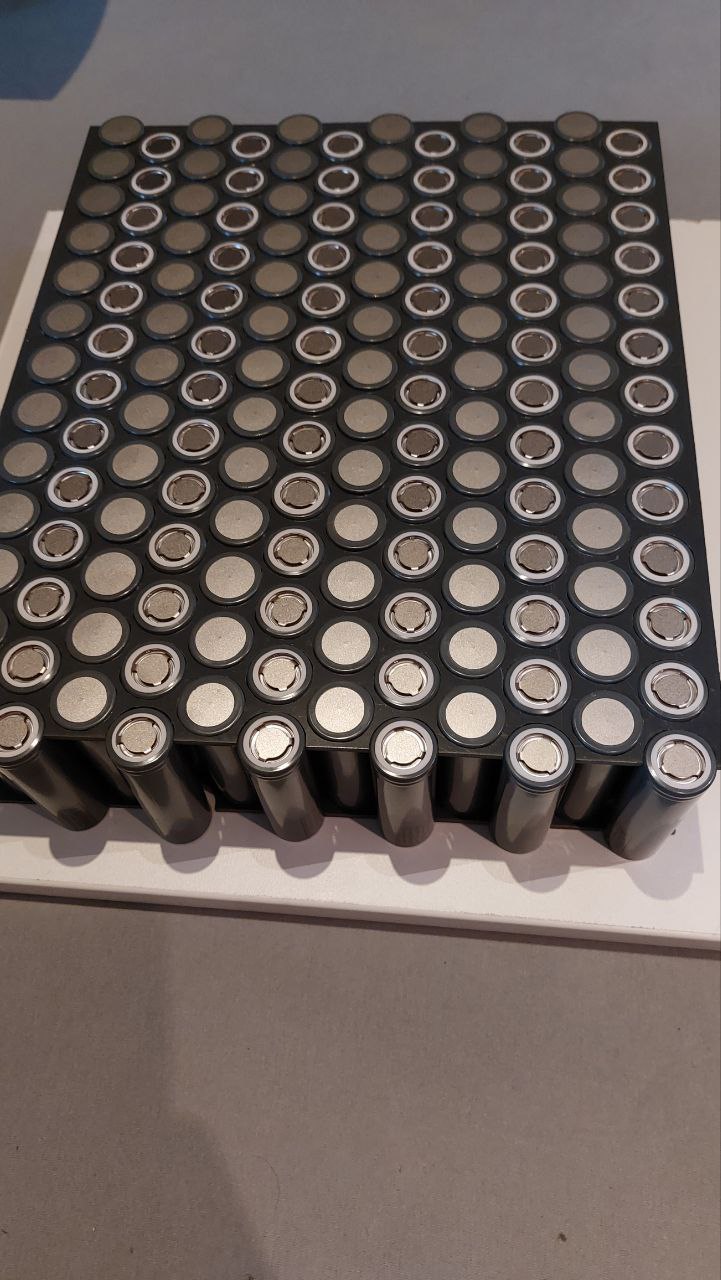
I chose LG M50LT cells because they are good value for money and deliver enough current.
Since I want to use the battery in all my boards, it is a little smaller 37x28x7.8cm. It is 12s13p, i.e. 2.85kwh, so I should not have any range problems.
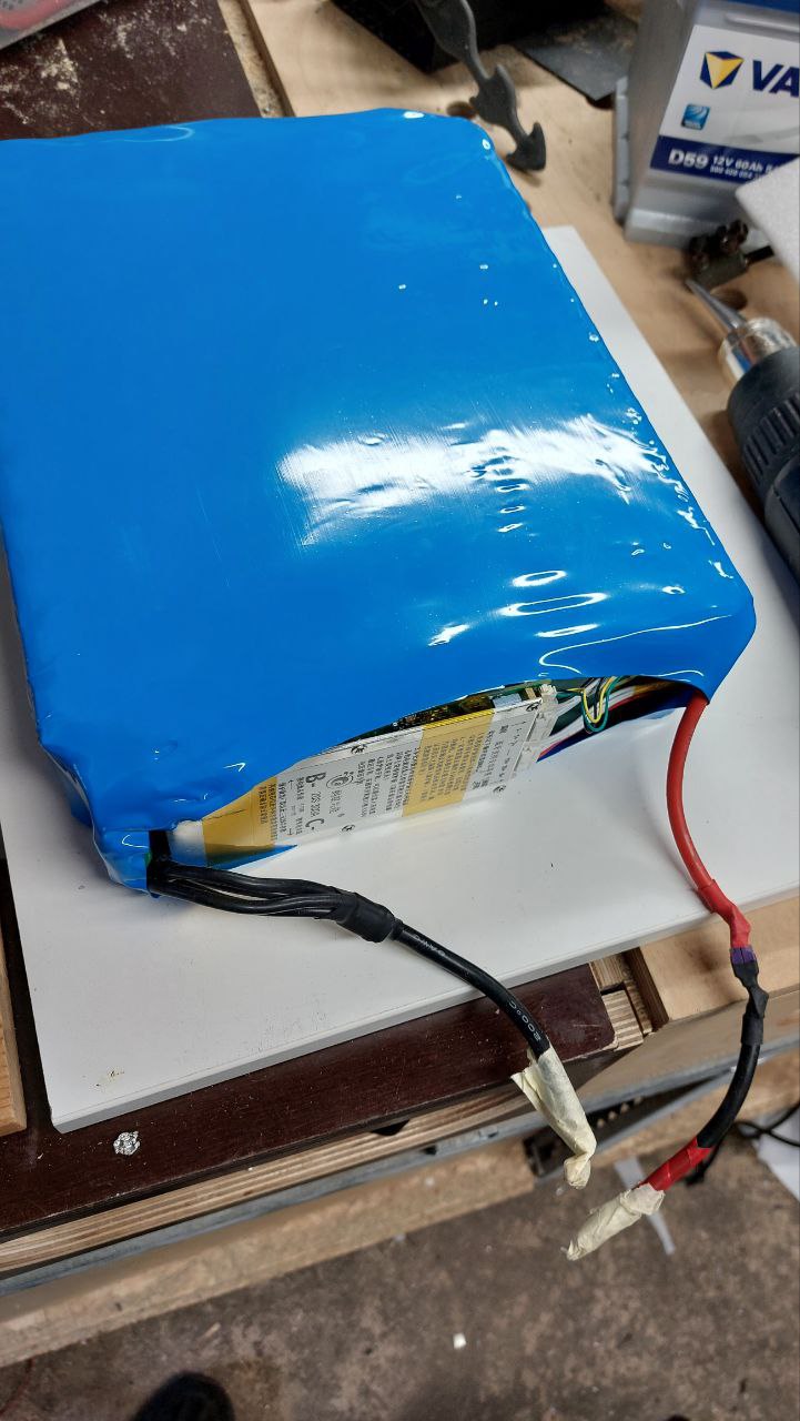
The special thing is that the housing is very robust, can be built in 30 minutes, is cheap and you don’t have to laminate a box. Yes, it is modelled on the Flitecell explore, but with a weight of less than 1 kg it is not particularly heavy. The total weight of the battery is 12.4kg, which I consider quite acceptable. A maximum of 14s14p with BMS or 14s15p will fit.
Then you would have 3.5kwh at 15kg weight.
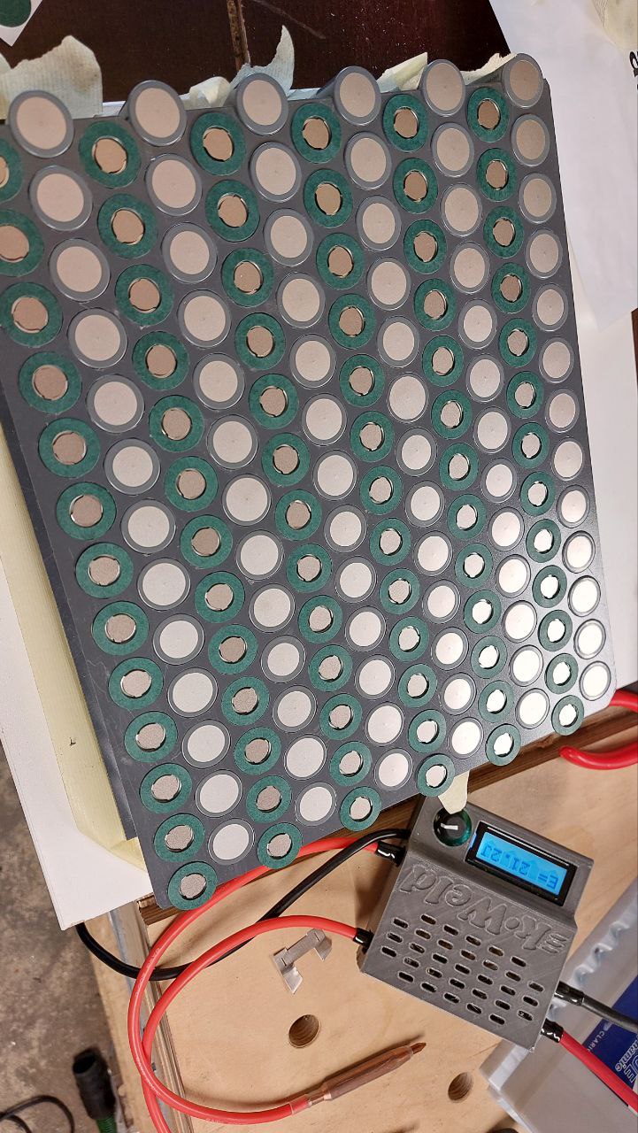
To save time, I also quickly milled the cell holders from 1mm instead of printing them.
The busbar and the balencer connections are simply folded to the side, as is usual, so as not to lose any height. A 200A mini ANL fuse is also installed for safety.
Nice build!
Would be nice if the battery “lock” system could be used to keep the battery in place.
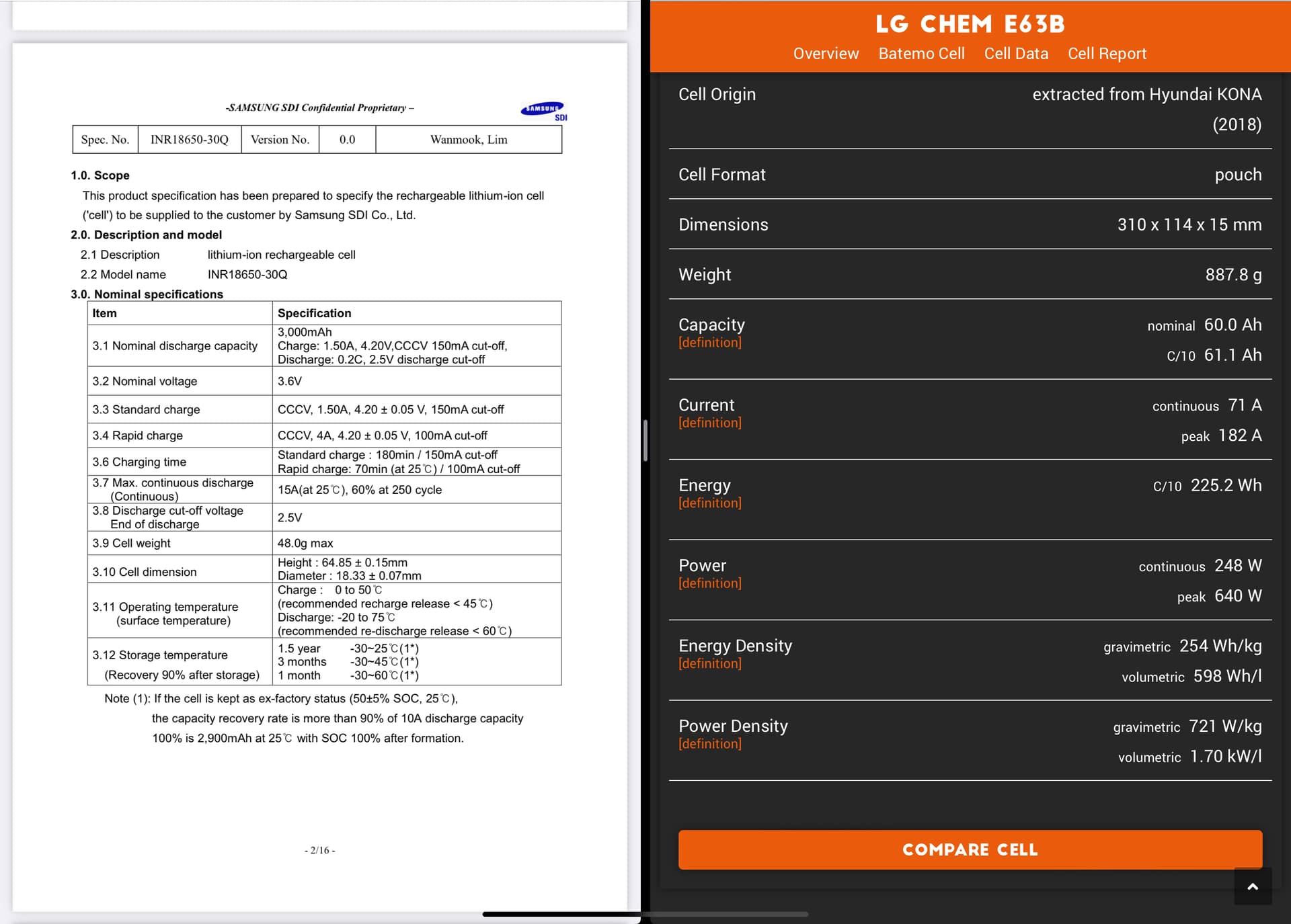
My next battery pack for the Fliteboard will be made out of lg chem e36b pouches.
Also. Did you notice that the box is a little bit tapered?
~Kian
I’m anything but a battery wizard so tried to compare a popular 18650 cell with the pouch you have chosen.
Looks like this
So roughly 20 cells = 1 pouch capacity
Pouch is lighter than 20 cells
What are your other variables in going with pouch as it’s the first design here that I’ve heard of using them?/
You think a 14s14p battery would fit with BMS? Any pics of the battery in the bay? Do you have a step file for the cell holders? That is slick.
At least 2 projects I remember of did use pouches.
Thanks I found one of them
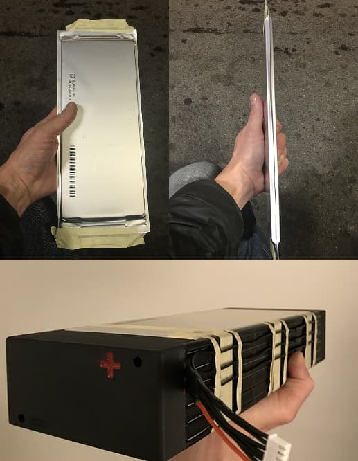
2018 KIA SOUL battery pouches, by @Riwi, NMC technology not Li-Ion
'Search results for 'KIA SOUL' - FOIL.zone
'The other way around - #21 by Riwi
The pack: 6s 42,5ah. 5kg. Size 360x130x65mm, 6 x 4.2 = 25.2V per pack, 2 pack in series = 50.4V
'26650 batterypack - #6 by Riwi
The tests:
'DIY lid for the electronics - #37 by Riwi